Table of Contents
Advertisement
Quick Links
Electromagnetic Flowmeter for
Partially-filled Pipes
Introduction
The LF502 electromagnetic flowmeter uses Faraday's
Law of electromagnetic induction in the same way as
conventional electromagnetic flowmeters to measure
the flow rate. Position of electrodes in the LF502 is so
designed that it can be used even in a partially-filled
pipe to measure the flow rate.
Improved functional magnetic field distribution
technique enables a high-precision flow measurement
continually from low-level to fully-filled flow
conditions. This eliminates unnecessary piping work
such as lifting the downstream pipe section to fill the
detector pipe.
Compared with flowmeters measuring the flow rate by
means of flow level, the obstruction less LF502
flowmeter does not usually allow mud, sands and other
solid sediment stay at the bottom of the detector pipe
and is unaffected by wave or floating solids on the fluid
surface.
The AF900 hand-held terminal (HART*
communicator) can be used to communicate with the
flowmeter from a remote place.
*1: HART protocol (Highway Addressable Remote
Transducer) is a communication protocol for industrial
sensors recommended by the HCF (HART
Communication Foundation).
Signal cable
Detector
Excitation cable
Figure 1. LF502/LF232*F Configuration
1
Converter
Power supply
4-20 mAdc
Digital I/O
LF502/LF232*F
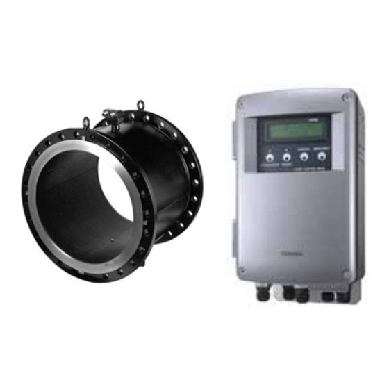
LF502
Figure 2. LF502 Electromagnetic Flowmeter
for Partially-filled Pipes
Specifications
■
Overall Specifications
Measurement range:
Meter size
0 – 264 GPM(std) to 0 – 1320 GPM
6" (150mm)
0 – 484 GPM(std) to 0 – 2420 GPM
8" (200mm )
0 – 770 GPM(std) to 0 – 3850 GPM
10" (250mm )
0 – 1100 GPM(std) to 0 – 5500 GPM
12" (300mm )
0 – 1540 GPM(std) to 0 – 7700 GPM
14" (350mm )
0 – 1980 GPM(std) to 0 – 9900 GPM
16" (400mm )
0 – 3124 GPM(std) to 0 – 15620 GPM
20" (500mm )
0 – 4400 GPM(std) to 0 – 22000 GPM
24" (600mm )
(0 – 1000 m
Note: Above flow rate is almost 0 – 3.28 ft/s (std) to 0 –
16.4 ft/s (0 – 1 m/s to 0 – 5 m/s ) flow velocity.
Fluid-level range:
Meter size
6" to 12" m
1-1/4"(30mm ) to fully-filled condition.
(150 to 300m )
14" to 24"
10% of inside tube diameter to
(350 to 600mm )
fully-filled condition.
Note: The fully-filled condition means a 100% of inside
tube diameter.
Accuracy: ±2% FS (when measurement range is
standard)
Note: The accuracy is measured under standard
operating conditions at Toshiba's calibration
facility.
6" to 24"
150
600
(
to
mm
LF232*F
Measurement range
3
3
(0 – 60 m
/h to 0 – 300 m
/h )
3
3
(0 – 110 m
/h to 0 – 550 m
/h )
3
3
(0 – 175 m
/h to 0 – 875 m
/h )
3
3
(0 – 250 m
/h to 0 – 1250 m
3
3
(0 – 350 m
/h to 0 – 1750 m
3
3
(0 – 450 m
/h to 0 – 2250 m
3
3
(0 – 710 m
/h to 0 – 3550 m
3
3
/h to 0 – 5000 m
Specification
TIC-LF502A
)
/h )
/h )
/h )
/h )
/h )
Advertisement
Table of Contents

Related Manuals for Toshiba LF232*F Series


Summary of Contents for Toshiba LF232*F Series
-
Page 1: Specifications
Transducer) is a communication protocol for industrial sensors recommended by the HCF (HART Communication Foundation). Converter Signal cable Detector Excitation cable Digital I/O Figure 1. LF502/LF232*F Configuration Figure 2. LF502 Electromagnetic Flowmeter Specifications ■ Overall Specifications Measurement range: Meter size 6” (150mm) 8”... - Page 2 Cable glands: Provided as standard, R(PT) 1/2 male screw. Applicable diameter: 0.433 to 0.512 inch (11 to 13mm ) ■ Model LF232*F converter Input signals Analog signal — the voltage signal from detector, proportional to process flow rate. Digital input DI (opt.)
- Page 3 Zero span calibration tool allows unit to be re-calibrated and verified using an internal software program. (For more information contact Toshiba International Corp.) Conditions when power fails: Parameter setting values are stored in non-volatile memory and the values will be restored when the power returns to normal condition The output and display will stay as follows when power fails..
-
Page 4: Installation
TIC-LF502A Installation ■ Dimensions Separate type LF502 (Meter size 6” and 8”) 3.46 (88) 1.42 (36) 1.57 (40) Figure 3. Detector Dimensions for Meter Sizes 6” (150 mm) and 8” (200 mm ) See the following tables for dimensions of L1, L2 and L3 in Figure 3 above, and the number of bolts required for each flange. - Page 5 ■ Dimensions 9.33 (237) 8.74 (222) 2.91 (74) Signal cable ground Output cable ground Grounding terminal 2.99 (76) 2.99 (76) 2.99 (76) Excitation cable ground 4-φ12 hole 6.10 (155) Power supply cable ground I/O cable ground Weight : Approximately18 lb (8 kg) (including a mounting bracket) Figure 5.
-
Page 6: Wiring Precautions
Thick walled steel conduit Detector Signal cable (2-wire shielded hard-rubber sheathed cable) (3-wire hard-rubber sheathed cable) Figure 6. LF502/LF232*F flowmeter Wiring Diagram ■ Wiring Precautions (1) Be sure to use thick walled steel conduit (22 mm) for signal and excitation cable wiring between the detector and converter. -
Page 7: Piping Precautions
■ Piping Precautions (1) Flange connection The flowmeter has upstream and downstream flanges on the ends of detector pipe. Connect these flanges with the flanges on both sides of pipeline bore using connection bolts after inserting a gasket between them. See Figure 7. Tighten the bolts in even increments diagonally across. - Page 8 Size groups A : 6” (150mm ) to 16” (400mm ) B : 20” (500mm ) and 24” (600mm ) Table 2. Specification Code for LF232*F converter Model Specification Code 1 2 3 4 5 6 7 8 9 10 11 12...
Need help?
Do you have a question about the LF232*F Series and is the answer not in the manual?
Questions and answers