Advertisement
Quick Links
Advertisement

Related Manuals for Toshiba LF810


Summary of Contents for Toshiba LF810
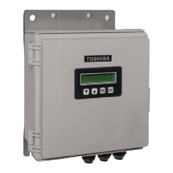
- Page 1 PRODUCT DATA SHEET Stationary Ultrasonic Flowmeter LF810 TOSHIBA INTERNATIONAL CORPORATION...
- Page 2 1. O Outline 1) Trans sit times of u ultrasonic pu ulses transm mitted in a liq quid vary wit th the flow v elocity of the e liquid and u ultrasonic flo owmeters ut ilize this cha aracteristic t o measure f flow.
- Page 3 Any languages are configurable on the PC locally. 3. Configuration Flowmeter components Component Model Quantity Description 1. Main unit LF810 1 pc Flowmeter main unit Ultrasonic transmit and receiving 1MHz Transducer 2. Transducers 2 pcs transducers and pipe-mounting fixtures for 1” – 24” Pipe...
- Page 4 1MHz transducer components are as follows. Weight Quantity Components Material (approx.) 1. Transducer 1pair (2pcs) Case : PBT (Plastic) 180g / 2pcs 2. Holder 2pcs PBT (Plastic) 160g / pc 3. Fastening Fixture 10pcs SUS304 20g / pc 4. Stainless Band 15 m SUS430 24g / m...
- Page 5 4. Specifications 4-1. Overall Specifications Measurement Fluids Homogeneous and ultrasonically conductive fluids (Clean water, waste water, industrial water, river water, sea water, pure water, etc.) Temperature range -4 to 140°F (-20 to 60°C) Note: 1) above also applicable to ambient temperature 2) For main unit, 14 to 122°F (-10 to 50°C) Turbidity 10000 mg/L or less...
- Page 6 4-2. Main Unit Analog Std / Option Standard output Number of channels Output contents Instantaneous flow rate Output pattern Single system 4 – 20mA, Burnout 20.8mA (when “no echo received” or during “failure warning” output available) Output format Max. allowable load resistance 600ohm Insulated outputs, 10-bit equivalent accuracy Update cycle 125ms (8Hz)
- Page 7 RS-485 Std / Option Option communication Number of channels Output format RS-485 (insulated type) Protocol MODBUS-RTU compatible Transmission Up to 1km (depending on cable and communication speed) Length Forward flow totalized value, backward flow totalized value, Data instantaneous flow rate, instantaneous flow velocity, equipment status, etc.
- Page 8 Display Display method LCD (16 character x 2 lines), with backlight The following items displayed in the upper and lower lines on LCD can be selected. • Instantaneous flow rate and units • Instantaneous flow velocity value and units • Forward flow totalized value and units •...
- Page 9 Function Cuts (Zeros) flow when flow falls below prescribed instantaneous Low flow cut flow rate. Used in order to avoid output of flow values other than 0 when measurement value during still flow becomes irratic. If measurement cannot be made when no echo is received continuously over the setting time , status is (determined transition time)
- Page 10 Function Automatic gain Receiver gain is automatically adjusted to the optimum level in (cont.) control response to changes in receiver sensitivity during measurement. (AGC Function) Totalized value Totalized values can be freely preset. preset Preset Range: 0 to 99999999 Error historic Count "No Echo receiving warning"...
- Page 11 4-3. Trans sducers Transduce 104720T Temperatu range -4 t to 140°F (-20 0 to 60°C) Protection 65 (When fill ed with resin n by the inst taller) class 67 as an opt ion (Resin-fi illed product t, shipped w with cable co onnected) Compatib cable...
-
Page 12: Transducer Installation
6. Transducer installation - To minimize measurement errors arising from flow profile, a straight pipe run is necessary for transducer installation. - Liquid should fill the pipes completely and transducers should be installed in locations which have no air bubbles. - For measurements in underground piping, the usual means is to locate the flowmeter in a pit to facilitate transducer installation, maintenance, and testing. - Page 13 7.Dim mension n s M M ain Unit D Dimension Transducer...
- Page 14 unting Fixt ure for Tra ansducer Mounting Fixture for r Transduc er (Z meth h od)
- Page 15 8. Wi iring Co onnectio 8-1. Out tput connec ction 8-2. Cab ble entry po Cable gland ds (I/O) Bottom vi iew of mai n unit case le gland (p power supp ply) USB-B c connector j able gland (Down-sid e transduc cer) ble gland (...
-
Page 16: System Wiring Connection
9. System Wiring Connection... - Page 17 10. Building a flowmeter pit Manhole Coaxial cable G.L. G.L. Flowmeter Pit Transducer Fastening Fixture Foot Step Stainless Steel Band >600mm Pipe Dia (d) >600mm V path method: d+1200mm Z path method: d/2+1200mm Water drainage 500×500×d300 - In principle, when measurement is of underground pipe, it is suggested to prepare dedicated flowmeter pit.
- Page 18 11. Ap ppendix Flow w Volume an nd Average F F low Velocity Average e Flow Velocity (m/s)
- Page 19 Specification Code Model number table Specification Model number code Contents ULTRASONIC FLOWMETER Power supply 100-230Vac,50/60Hz 24Vdc±20% Transducers Type Standard (requires connecting to cables) Factory epoxy potting (Meets IP67, includes connecting cables to transducers only) I/O card No need Rs-485 Modbus Communication Card Analog Input Card(1ch) Both of RS-485 Modbus and Analog Input Mounting for Main unit...
- Page 20 INDUSTRIAL DIVISION 13131 WEST LITTLE YORK ROAD HOUSTON, TX 77041 PHONE: (713) 466-0277 (800) 231-1412 FACSIMILE: (713)896-5225 EMAIL: instrument@tic.toshiba.com www.toshiba.com/ind...
Need help?
Do you have a question about the LF810 and is the answer not in the manual?
Questions and answers