Table of Contents
Advertisement
Quick Links
NOTES
Before using the equipment, please read this manual carefully and understand the
contents, and then use the equipment correctly.
• NEVER attempt to operate the equipment in any ways that are not described in this
instruction manual.
• After reading this manual, store it with care in a place where it can be referred to
whenever needed.
• Please be sure that this manual is delivered to the personnel who will use this
product.
Buy: www.ValinOnline.com | Phone 844-385-3099 | Email: CustomerService@valin.com
Electromagnetic Flowmeter Converter
LF620F Type, LF622F Type
INSTRUCTION MANUAL
6 F 8 A 0 9 2 8
Advertisement
Table of Contents
Troubleshooting

Related Manuals for Toshiba LF620F


Summary of Contents for Toshiba LF620F
- Page 1 6 F 8 A 0 9 2 8 Electromagnetic Flowmeter Converter LF620F Type, LF622F Type INSTRUCTION MANUAL NOTES Before using the equipment, please read this manual carefully and understand the contents, and then use the equipment correctly. • NEVER attempt to operate the equipment in any ways that are not described in this instruction manual.
- Page 2 LF620F Separate type converter LF622F: LF622F Toshiba LF62*F series electromagnetic flowmeter converters can be used in combination with various types of electromagnetic flowmeter detectors. For the notes on usage, piping, installation, configuration and maintenance of the combined detector, check the model number of the combined detector and read the instruction manual of the relevant detector.
- Page 3 6 F 8 A 0 9 2 8 SAFETY PRECAUTIONS Safety signs and labels affixed to the product and/or described in this manual give important information for using the product safely. They help prevent damage to property and obviate hazards for persons using the product.
- Page 4 6 F 8 A 0 9 2 8 SAFETY PRECAUTIONS (continued) Safety Precautions for Hazardous Locations WARNING Do not disconnect while circuit is live unless location is known to be nonhazardous. Live part of electric circuit or a high temperature department can cause explosion. DON’T Do not modify or disassemble the enclosure.
- Page 5 Use crimped terminal lugs for the terminal Do not modify or disassemble the LF620F and board and GND terminal. LF622F unnecessarily. Loose connections can Modifying or disassembling this...
- Page 6 Warranty and Limitation of Liability Toshiba does not accept liability for any damage or loss, material or personal, caused as a direct or indirect result of the operation of this product in connection with, or due to, the occurrence of any event of force majeure (including fire or earthquake) or the misuse of this product, whether intentional or accidental.
- Page 7 6 F 8 A 0 9 2 8 Handling Precautions To obtain the optimum performance from the LF620F and LF622F converter for years of continuous operation, observe the following precautions. (1) Do not store or install the flowmeter in : ・Where there is direct sunlight.
- Page 8 6 F 8 A 0 9 2 8 Handling Precautions (continued) (6) Observe the following precautions when you open the converter housing cover: • Do not open the cover in the open air unprotected against rain or wind. This can cause electric shock or cause damage to the flowmeter electronics.
-
Page 9: Table Of Contents
Appearance of LF620F Type......................13 3.1.2 Appearance of LF622F Type......................14 Construction of the terminal blocks........................ 15 3.2.1 Terminal Block Construction of LF620F Type ................. 15 Installation ................................16 Notes on Selecting the Installation Location....................17 How to Install..............................18 4.2.1 LF620F Type ........................... - Page 10 6 F 8 A 0 9 2 8 Parameter Settings..............................54 Parameter Setting Items..........................54 Check/Change of Parameters ........................55 8.2.1 Menu Configuration Selection Screen ..................... 55 8.2.2 Exciting Current Value........................56 8.2.3 Meter Size ............................57 8.2.4 Exciting Frequency.......................... 59 8.2.5 Flow Direction Setting........................
- Page 11 14. Principle of Operation............................149 15. Specifications ............................... 150 15.1 Specifications .............................. 150 15.2 Model Number Table ........................... 153 16. Outline Drawing..............................154 16.1 LF620F Type ............................... 154 16.2 LF622F Type ............................... 155 Appendix1..................................156 Appendix2..................................158 - 10 -...
-
Page 12: Product Inspection And Storage
Inspect the flowmeter for indications of damage that may have occurred during shipment. Make sure the type and specifications of the flowmeter are in accordance with the ordered specifications. If you cannot find the items listed above or any problem exists, contact your nearest Toshiba representative. 1.2 Storage... -
Page 13: Overview
6 F 8 A 0 9 2 8 2. Overview The LF620F and LF622F electromagnetic flowmeter converter can be use in the following hazardous (classified) locations. ClassⅠ, Division 2, Groups A, B, C and D, ClassⅡ, Division 2, Groups E, F and G ClassⅢ... -
Page 14: Names Of Parts
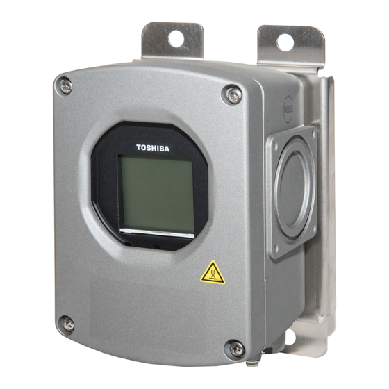
The cable connections are not provided in the conduit port of this apparatus. Please prepare yourself for the cable connections, which could be used in Division2 hazardous locations. 3.1 Appearance 3.1.1 Appearance of LF620F Type LF620F Control key Display section... -
Page 15: Appearance Of Lf622F Type
6 F 8 A 0 9 2 8 3.1.2 Appearance of LF622F Type LF622F Display section Converter installation screw Converter case Control key (Control panel) for excitation cable for signal cable Ground terminal for power cable for signal cable for flow rate signal cable Figure 3.1.2 Appearance of LF622F -... -
Page 16: Construction Of The Terminal Blocks
3.2 Construction of the terminal blocks 3.2.1 Terminal Block Construction of LF620F Type When you remove the terminal block cover shown in the figure "Appearance of LF620F and LF622F Type", you can see the converter terminal block as shown below. -
Page 17: Installation
Do not modify or disassemble the Ground the LF620F and LF622F LF620F and LF622F unnecessarily. independently from power equipment. (100 ohm or less ground resistance) Modifying or... -
Page 18: Notes On Selecting The Installation Location
6 F 8 A 0 9 2 8 4.1 Notes on Selecting the Installation Location This product is designed for the following environment. ・Indoor and outdoor installation ・Ambient temperature: - 4 to 140°F (-20 to +60℃) ・Altitude:Up to 2000m ・Humidity range:10 to 90%(no condensation) ・Regulation of power voltage:±10% ・Pollution degree 2 ・Structure:IP67 and NEMA 4X... -
Page 19: How To Install
4.2 How to Install 4.2.1 LF620F Type The LF620F type converter is used as one united body. The LF620F type is not installed by itself. For how to install the LF620F type converter and a detector, check the type of the combined detector and follow the instruction manual for the relevant detector. - Page 20 6 F 8 A 0 9 2 8 Unit : inch (mm) Panel or wall mounting dimensions Figure 4.1 Examples of Installation to Panel and Wall - 19 - Buy: www.ValinOnline.com | Phone 844-385-3099 | Email: CustomerService@valin.com...
- Page 21 6 F 8 A 0 9 2 8 Unit : inch (mm) M10U bolt 50A pipe (2B pipe) etc. Figure 4.2 Example of Pipestand Mounting - 20 - Buy: www.ValinOnline.com | Phone 844-385-3099 | Email: CustomerService@valin.com...
-
Page 22: Wiring
6 F 8 A 0 9 2 8 5. Wiring Notes on wiring WARNING DO NOT DISCONNECT WHILE CIRCUIT IS LIVE UNLESS LOCATION IS KNOWN TO BE NONHAZARDOUS. Live part of electric circuit or a high temperature department can cause explosion. DON’T Do not activate circuits while assembly of all components is not over. - Page 23 6 F 8 A 0 9 2 8 CAUTION Install a switch and fuse to isolate the Turn off mains power before conducting LF620F and LF622F from mains power. wiring work. Power supply from mains Wiring while power is applied power can cause electric shock can cause electric shock.
-
Page 24: Cables
6 F 8 A 0 9 2 8 CAUTION (1) Select the cable run location so they are away from electrical equipment (motors, transformers, or radio transmitters) which causes electromagnetic or electrostatic interference. (2) Deterioration of flowmeter circuit insulation occurs if the converter interior or cable ends get wet or humidified. -
Page 25: External Device Connections And Grounding
6 F 8 A 0 9 2 8 5.2 External Device Connections and Grounding 5.2.1 LF620F Type The terminal board connections of an integral type converter LF620F are shown in Figure 5.1. Proceed with wiring as described in Section 5.4, “Wiring Procedure.” LF620F Instrument panel : Ordered separately Grounding with 100Ω... -
Page 26: Lf622F Type
6 F 8 A 0 9 2 8 5.2.2 LF622F Type The terminal board connections of separate type converter LF622F are shown in Figure 5.1. Proceed with wiring as described in Section 5.4, “Wiring Procedure.” LF622F Instrument panel : Ordered separately Grounding with 100Ω... -
Page 27: Notes On Wiring
When a 3-core cable is used: Ground with the FG terminal. When a 2-core cable is used: Use an external grounding terminal and make the cable as short as possible. Note that, for a replacement from the Toshiba electromagnetic flowmeter converter LF220 type, the cable grounding position differs. -
Page 28: Wiring
• If the piping material is non-conductive, perform 100Ω or more the grounding wires to the both ends of the grounding resistance 100Ω or less. piping flange. Figure 5.3 Grounding the LF620F Type - 27 - Buy: www.ValinOnline.com | Phone 844-385-3099 | Email: CustomerService@valin.com... - Page 29 6 F 8 A 0 9 2 8 (2) Grounding the LF622F type LF622F Ground the external grounding terminal of the detector and the FG terminal of the converter (or external grounding terminal of the converter) securely (grounding resistance 100Ω or lower). Use grounding wire material of IV wire 5.5mm or more.
-
Page 30: Terminal Treatment Of Cables
6 F 8 A 0 9 2 8 5.4.2 Terminal Treatment of Cables Follow the procedures below to treat the terminals (at the converter side) of various cables and install the cables to the terminal block. Use appropriate cables based on the description in Section 5.1 "Cables." Crimp a round type insulated crimp-type terminal to the end of the cables. - Page 31 6 F 8 A 0 9 2 8 (3) Connecting the input signal cable: LF622F Strip the sheath from the end of each conductor of a 2-core individually shielded cable as shown in Figure 5.9. Twist those shields and cover them with a thermal contraction tube or vinyl tube not to make contact with the case or core wires.
-
Page 32: Cable Connection
6 F 8 A 0 9 2 8 5.4.3 Cable Connection (1) Connect and install the terminal-treated cables to the terminal block by the following procedure. *Connect the cables to the terminal block securely. A loose connection may cause incorrect measurement. -
Page 33: Digital I/O Connections
6 F 8 A 0 9 2 8 5.5 Digital I/O Connections Digital I/O terminals consist of contact output terminals (DO1 and DO2), voltage signal input terminal (DI), and signal common terminal (COM). Each terminal (DO1, DO2 and DI) is isolated from internal circuits. -
Page 34: Operation
6 F 8 A 0 9 2 8 6. Operation CAUTION Do not touch the terminal board when power Do not touch the main body when high is supplied. temperature fluid is being measured. Touching the terminal board The fluid raises the main body when power is supplied can temperature and can cause burns. -
Page 35: Zero Adjustment
6 F 8 A 0 9 2 8 Note 1: If the detector pipe is not filled with the fluid to be measured, the flow rate will be indefinite and unable to be measured. Before using the flowmeter, be sure to fill the detector pipe the fluid to be measured. -
Page 36: Lcd Display And Controls
Control key (Control panel) Control key (Control panel) Fig. 7.1 Display section of LF620F Fig. 7.1 Display section of LF622F Instructions The operation principle of infrared switch is to irradiate infrared to the front of control panel and detect the reflection from finger when operating. - Page 37 6 F 8 A 0 9 2 8 ● LCD electronically rotatable display The backlit display provides an easy-to-read indication even under poor lighting conditions. Instantaneous flow rates or totalized flow in the measurement mode or configuration parameters in the setting mode can be displayed.
- Page 38 6 F 8 A 0 9 2 8 ● Setting switch The control keys allow you to perform converter control and setting, without opening the converter housing. These three controls keys function differently depending on the current display screen. The functions of these control keys are displayed on the display screen. In this product, the display method can be changed according to the converter installation direction.
-
Page 39: Display Format
6 F 8 A 0 9 2 8 7.2 Display Format In the measurement mode, the measured data is displayed using the menu items set by the Display 1 (DSPL1) and Display 2 (DSPL2). (For display settings, see 8.2.6 "Display Setting.") ・... - Page 40 6 F 8 A 0 9 2 8 Note 1: Totalized flow volume and totalized difference flow volume are displayed to the least significant digit of the set count rate. (Example1) When the count rate is 0.0001 m When the measurement object flows through 0.0001(m ), inside counter counts 1.
- Page 41 6 F 8 A 0 9 2 8 ・ Percent display Numeric value・・・Within the range of +125.0% to −125%, - 1 2 5 . 0 displayed to the decimal place of 0.1%. Unit・・・ "%" fixed. * If the value goes out of the display range, an error message appears. ・...
- Page 42 6 F 8 A 0 9 2 8 ・ Bar graph display Bar graph can be set only for Display 2. Graph・・・ The measured value is displayed in bar graph. The left side of the graph is RL (Range Low limit) and the right side of the graph is RH (Range High limit).
-
Page 43: Basic Operations
6 F 8 A 0 9 2 8 7.3 Basic operations 7.3.1 Mode Change The converter provides the setting mode and calibration mode as well as the measurement mode. To change the mode to the setting mode or to the calibration mode, push the switch. - Page 44 6 F 8 A 0 9 2 8 ○Flow of mode change Note: When the screen is switched, let your * (L) indicates that you can hold down the switch longer. finger off the switch. If you keep pushing, the * <L>...
- Page 45 6 F 8 A 0 9 2 8 ○ Pulse output setting mode This mode is used to perform continuous parameter settings (automatic operation) regarding pulse outputs. When these parameters are set, pulse output is ready to send out. PLS WID CNT RATE MENU SEL DO1 FUNC...
- Page 46 6 F 8 A 0 9 2 8 ○ Explanation about mode change The converter usually works continuously in the measurement mode. If you want to set parameters or perform calibration or adjustment, you have to go to the setting mode. To enter the setting mode, push the center switch for 3 seconds or more in the measurement mode.
-
Page 47: Setting And Calibration
6 F 8 A 0 9 2 8 ○ Operation timeout function If no operation is made for one minute or more while the converter is in the setting mode, the mode automatically returns to the measurement mode unless the parameters are displayed on the screen. - Page 48 6 F 8 A 0 9 2 8 Switch operation Display example Description A:DETECTOR Pushing from the menu configuration 1 EXC CUR selection screen takes you to the menu 2 SIZE screen. 3 EXC FREQ The cursor is positioned at the function 4 FLOW DIR display ([A: DETECTOR] in this example).
- Page 49 6 F 8 A 0 9 2 8 Switch operation Display example Description Push to select the item you want to check or change. 10.0000 The screen changes and the currently set item appears for you to check. Pushing returns you to the menu screen.
- Page 50 6 F 8 A 0 9 2 8 Switch operation Display example Description Pushing when data is temporarily set causes the data to be fixed and executed. 5.00000 After the data is set, the cursor disappears, enabling you to check the set value. C:RANGE Pushing returns you to the menu...
-
Page 51: Configuration Items Selection Table
6 F 8 A 0 9 2 8 7.4 Configuration Items Selection Table How to check or change each constant of the converter is shown in the table below. Details of each item are described in the setting items (A to R) of Chapter 8, "Parameter Settings." ○... - Page 52 6 F 8 A 0 9 2 8 ○ Detailed configuration When you select "DETAILED" in the menu configuration selection screen, the check/change menu for each constant setting is expanded as shown in the table below. Function Exciting Returns Exciting Meter size Flow frequency...
-
Page 53: Password Input
6 F 8 A 0 9 2 8 7.5 Password input The converter provides the password function to prohibit some functions that affect the flow measurement from being set or adjusted. For the protected functions, see the menu configuration table on the previous page. - Page 54 6 F 8 A 0 9 2 8 • Limitation of settings and adjustments The items enclosed by thick lines below can only be changed or adjusted (others can only be displayed). However, for items protected by password, they can be changed only when the password input matches.
-
Page 55: Parameter Settings
6 F 8 A 0 9 2 8 8. Parameter Settings 8.1 Parameter Setting Items To check or change each constant of the converter, first select the desired setting item described in 7.3.2 “Setting and Calibration.” Proceed as follows for settings in the setting mode. Function item Display example 8.2.2... -
Page 56: Check/Change Of Parameters
6 F 8 A 0 9 2 8 8.2 Check/Change of Parameters 8.2.1 Menu Configuration Selection Screen Display example MENU SEL BASIC DETAILED PREVIEW ZERO ADJ PLS SET You can select the kind of menu configuration. For menu items of configuration, see 7.4 "Setting and Calibration Items List." Only the basic parameters are displayed. -
Page 57: Exciting Current Value
6 F 8 A 0 9 2 8 8.2.2 Exciting Current Value The exciting current value can be checked/changed by the following procedures. Be sure to match the exciting current value with the value specified for the combined detector. Specifying any other value may cause an error. Shown below is an example of changing the exciting current value from 0.1900A to 0.2150A. -
Page 58: Meter Size
6 F 8 A 0 9 2 8 Switch operation Display example Description EXC CUR STEP6 Pushing shows a message to confirm the setting is OK or not. 0.2150 If OK, push . If you need to redo the setting, push Pushing cancels the setting operation SET OK? - Page 59 6 F 8 A 0 9 2 8 Switch operation Display example Description SIZE STEP4 Repeat this operation until 150mm is obtained. When the desired value is obtained, push to set the value temporarily. SIZE STEP5(=END) Pushing shows a message to confirm whether the setting is OK or not.
-
Page 60: Exciting Frequency
6 F 8 A 0 9 2 8 8.2.4 Exciting Frequency You can select an exciting frequency of 6Hz, 12Hz or 24Hz. Since each exciting frequency value has its own characteristics, you should select an appropriate exciting frequency (24Hz is set at shipment. Depending on the characteristics of the detector, a large frequency may result in excitation failure. -
Page 61: Flow Direction Setting
6 F 8 A 0 9 2 8 Switch operation Display example Description EXC FREQ STEP3 You can continue to change the setting item. Pushing changes the selection items. : Selected item is scrolled up. : Selected item is scrolled down. EXC FREQ STEP4 Repeat this operation to select 12Hz. -
Page 62: Display Setting
6 F 8 A 0 9 2 8 Switch operation Display example Description FLOW DIR STEP1 The currently set flow direction (NORMAL in this example) appears. NORMAL Then push * Pushing returns you to the setting menu. FLOW DIR STEP2 The switches at the bottom change. - Page 63 6 F 8 A 0 9 2 8 Note 1: If COUNT, RANGE, GRAPH or CUSTOM is selected, the display is shown below: COUNT: displays the totalized flow counts (up to 8 digits). RANGE: displays the range number being used for measurement (1 to 4). GPARH: displays the measured value (% value) in bar graph.
- Page 64 6 F 8 A 0 9 2 8 GRAPH CUSTOM RANGE COUNT Note 2: The second unit (time unit) changes as shown below: /min For Display 2 unit setting, select DSPL2 from the setting menu. ● How to select the display digit setting When you select flow velocity or flow rate (custom unit is included), the screen automatically moves to the display digit setting screen.
- Page 65 6 F 8 A 0 9 2 8 For example, if the setting range is 10m/s and display digit setting is 1/100, the measured value will be displayed to the first decimal place. Setting range=10.0000 m/s One hundredth of Maximum effective digits maximum effective digits Likewise, when the setting range 1m/s and display digit setting is 1/100, the measured value will be displayed to the second decimal place.
-
Page 66: Custom Coefficient Setting
6 F 8 A 0 9 2 8 Note: The setting item for the third unit (flow volume direction code) changes cyclically as shown below. B(bi-directional) F(forward direction fixed) R(reverse direction fixed) C(cyclic) D(difference flow rate) When C(cyclic) is selected, totalizer of forward, reverse and difference are displayed at cycle about 5 seconds. -
Page 67: Custom Unit Setting
6 F 8 A 0 9 2 8 Switch operation Display example Description CS VAL STEP4(=END) Pushing shows a message to confirm whether the setting is OK or not. 2.25000 If OK, push . If you need to redo the setting, push SET OK? Pushing... -
Page 68: Span (Range)
6 F 8 A 0 9 2 8 Switch operation Display example Description CS UNIT STEP4(=END) Pushing when the cursor is positioned on the 7th character shows a message to XXX/ZZZ confirm whether the setting is OK or not. If OK, push . - Page 69 6 F 8 A 0 9 2 8 ● Span You can set the span for actual flow rate or flow velocity. (1) Setting range The span can be set within 0.1 m/s to 10 m/s in terms of flow velocity. If you try to set the span outside of this range, either high limit or low limit error message appears: HIGH OVER SPEC (if the set value exceeds 10 m/s)
- Page 70 6 F 8 A 0 9 2 8 ● Range hysteresis The hysteresis is the dead band used when multiple ranges are switched. You can set the hysteresis within the range of 0 to 25% in increments of 0.1%. The hysteresis is set only when automatic selection of multiple ranges is used. ●...
- Page 71 6 F 8 A 0 9 2 8 Switch operation Display example Description C:RANGE Pushing returns you to the setting 1 R TYPE menu. 2 R1 3 R2 4 R3 5 R4 6 R HYS 7 EXIT ● Changing the range type The range type should be set before changing the span.
- Page 72 6 F 8 A 0 9 2 8 Switch operation Display example Description R TYPE STEP5(=END) When you push , a message appears to confirm whether the setting is OK or not. 2F-2R If OK, push . If you want to redo the setting, push SET OK? Pushing...
- Page 73 6 F 8 A 0 9 2 8 Switch operation Display example Description STEP6 Push to change the number of the digit. 136.000 Push to move the digit. L/min STEP7(=END) When you push , a message appears to confirm whether the setting is OK or not. 100.000 If OK, push .
-
Page 74: Damping Constant
6 F 8 A 0 9 2 8 Switch operation Display example Description R HYS STEP3 Push to move the cursor to the desired digit and push to change the 05.0 number of the digit. R HYS STEP4(=END) When you push , a message appears to confirm whether the setting is OK or not. -
Page 75: Rate-Of-Change Limit And Control Limit Time
6 F 8 A 0 9 2 8 Switch operation Display example Description DAMPING STEP2 The switches at the bottom change. are shown.) 02.0 At the same time, the cursor appears. DAMPING STEP3 Push to move the cursor to the desired digit and push to change the 10.0... - Page 76 6 F 8 A 0 9 2 8 ● Changing the rate-of-change limit The following is an example to change the rate-of-change limit value from 10.0% to 15.0%. Switch operation Description Display example D:FILTER Select "LIM RATE" from the setting item 1 DAMPING selection menu.
-
Page 77: Low Cutoff
6 F 8 A 0 9 2 8 8.2.12 Low Cutoff The low cutoff is the function to set the current output to zero forcefully if the flow rate is equal to or less than the low cutoff value set near 0%. The low cutoff value can be set within the range 0 to 10% in increments of 0.1%. -
Page 78: Display Low Cutoff
6 F 8 A 0 9 2 8 8.2.13 Display Low Cutoff When low cutoff is set in 8.2.12 “Low Cutoff,” this function determines whether to use the low cutoff processing for displayed values. You can select the display low cutoff setting from the items in the table below. ●... -
Page 79: Still Water Zero Adjustment
6 F 8 A 0 9 2 8 Switch operation Display example Description DSPL SET STEP4(=END) When you push , a message appears to confirm whether the setting is OK or not. LOW CUT If OK, push . If you want to redo the setting, push SET OK? Pushing... -
Page 80: Manual Zero Adjustment
6 F 8 A 0 9 2 8 8.2.15 Manual Zero Adjustment This function is used to perform zero adjustment simply by comparing the output value of the converter with the process value of other instruments without stopping the process of measurement. If zero adjustment described in 8.2.14, “Still Water Zero Adjustment”... -
Page 81: 4−20Ma Alarm Output Setting
6 F 8 A 0 9 2 8 Switch operation Display example Description MANUAL STEP3 Push to move the cursor to the desired digit and push to change the -002.5 symbol or number of the digit. MANUAL STEP4(=END) Pushing shows a message to confirm whether the setting is OK or not. -
Page 82: Output Low Limit Setting
6 F 8 A 0 9 2 8 Switch operation Display example Description ALM 4-20 STEP1 The currently set value (UNDER 3.0mA in this example) appears. UNDER 3mA Then push * Pushing returns you to the setting menu. ALM 4-20 STEP2 The switches at the bottom change. -
Page 83: Digital Output
6 F 8 A 0 9 2 8 You can check or change the output low limit as described below. The following is an example to change the output low limit value from 4.0mA to 2.4mA. Switch operation Display example Description G:4-20mA Select "LOW LIM"... - Page 84 6 F 8 A 0 9 2 8 ●Digital output functions Selection items Digital output functions NO USE Not used H ALM High alarm output L ALM Low alarm output HH ALM High-High alarm output LL ALM Low-Low alarm output EMPTY ALM Empty pipe alarm output RNG SIG1...
-
Page 85: Digital Input
6 F 8 A 0 9 2 8 Switch operation Display example Description DO1 FUNC STEP2 The switches at the bottom change. are shown.) H ALM At the same time, the cursor appears. (The item indicated by the cursor is highlighted.) Then push DO1 FUNC... - Page 86 6 F 8 A 0 9 2 8 ●Digital input control signal You can select the detective level of the digital input, as shown below, to control the totalizer and pulse output. (Only when the digital input function is set for totalizer control input) Selection items Digital input function setting Totalizer control signal...
-
Page 87: Count Rate (Pulse Rate), Pulse Width Setting Mode And Pulse Width
6 F 8 A 0 9 2 8 Switch operation Display example Description DI FUNC STEP4(=END) When you push , a message appears to confirm whether the setting is OK or not. CNT ST/SP If OK, push . If you want to redo the setting, push SET OK? Pushing... - Page 88 6 F 8 A 0 9 2 8 ● For pulse width setting mode, you can select either AUTO or MANUAL. Depending on this setting, the pulse width setting varies as shown in the table below: Selection item Pulse width value to be set After the count rate is set, the pulse width is automatically set AUTO to 40% of the period of pulse frequency at 100% output.
- Page 89 6 F 8 A 0 9 2 8 You can check or change the count rate and pulse width as described below. The following is an example to change the count rate from 0.01m to 0.9 L. Switch operation Display example Description CNT RATE STEP1...
-
Page 90: Preset Count
6 F 8 A 0 9 2 8 Note 1: The units of count rate change cyclically as shown below: m³ Mgl = 1,000,000 gal Note 2: After the count rate is set, related parameters are automatically set under the following conditions: (1) Pulse width When the pulse width setting mode is AUTO:... - Page 91 6 F 8 A 0 9 2 8 You can check or change the preset count as described below. The following is an example to change the preset count value from 500 (count) to 1000 (count). Switch operation Display example Description K:PRESET C Select "PRST VAL"...
-
Page 92: Preset Mode
6 F 8 A 0 9 2 8 8.2.22 Preset Mode The preset mode determines the function when the totalizer reaches the preset count. The present mode can be set from the items shown below. ●Preset mode Selection items Preset mode HOLD Holds the output value. -
Page 93: Flow Rate High/Low Alarm And High-High/Low-Low Alarm
6 F 8 A 0 9 2 8 Switch operation Display example Description OUT MODE STEP2 The switches at the bottom change. are shown.) HOLD At the same time, the cursor appears. (The item indicated by the cursor is highlighted.) Then push OUT MODE STEP3... - Page 94 6 F 8 A 0 9 2 8 Switch operation Display example Description H SET STEP2 The switches at the bottom change. are shown.) At the same time, the cursor appears. (The item indicated by the cursor is highlighted.) Then push H SET STEP3 You can continue to change the setting item.
-
Page 95: Empty Pipe Alarm Setting
6 F 8 A 0 9 2 8 Switch operation Display example Description H VAL STEP3 Push to move the cursor to the digit you want to change and push +103.0 to change the number of the digit. H VAL STEP4(=END) When you push , a message appears... -
Page 96: Mag-Prover-Self Diagnosis On/Off Setting
6 F 8 A 0 9 2 8 Switch operation Display example Description EMPTY STEP1 The current setting (OFF in this example) appears. Then push * Pushing returns you to the menu screen. EMPTY STEP2 The switches at the bottom change. are shown.) At the same time, the cursor appears. -
Page 97: Converter Alarm
6 F 8 A 0 9 2 8 ●Changing the Mag-Prover’s self-diagnosis function setting The following is an example to change the Mag-Prover’s self-diagnosis setting from OFF to ON. Switch operation Display example Description N:SELF CHK Select "SELF CHK" from the setting item 1 EMPTY selection menu. -
Page 98: Fixed Value Output
6 F 8 A 0 9 2 8 ●Changing the converter alarm function The following is an example to change the converter alarm function from WITH EMP to CONV ONLY. Switch operation Display example Description N:SELF CHK Select "CONV ALM" from the setting item 1 EMPTY selection menu. - Page 99 6 F 8 A 0 9 2 8 Operation when fixed output is set to ON Current output Output is the fixed current output value. Pulse output Output is the fixed pulse rate pulse signal. Digital output other than Status in hold pulse output Display Display 2 screen: Used to indicate the fixed output...
- Page 100 6 F 8 A 0 9 2 8 Switch operation Display example Description FIX SET STEP4 When you push , a message appears to confirm whether the setting is OK or not. If OK, push . If you want to redo the setting, push SET OK? Pushing...
-
Page 101: Password Setting
6 F 8 A 0 9 2 8 Note 1: If you try to set a value outside of the range, 2.4mA or 24mA (in the case of fixed current output) or 10000pps (in the case of fixed pulse output) will be forcibly set. Note 2: The pulse width set in Section 8.2.20 is used for fixed pulse output. - Page 102 6 F 8 A 0 9 2 8 * However, if a wrong password is entered when the mode is changed from the measuring mode to the setting mode, *** appears and the password cannot be checked. Switch operation Description Display example PASSWORD The currently set password is displayed as...
-
Page 103: Lcd Adjustment
6 F 8 A 0 9 2 8 8.2.29 LCD Adjustment This section describes how to set the LCD density adjustment value for the converter display. The LCD density can be set in 5 levels. LCD density adjustment level LCD density Light Dark The LCD density adjustment value is set to "3"... -
Page 104: Switch Position Setting
6 F 8 A 0 9 2 8 8.2.30 Switch Position Setting The switch position of the converter display can be set. The position setting of the switch enables the display remains the same in orientation, regardless of which direction relative to the piping the converter is installed. You can set the switch position by selecting one from four positions described below. -
Page 105: Communication Setting
6 F 8 A 0 9 2 8 The following is an example to change the switch position setting from BOTTOM to TOP. Switch operation Description Display example P:OTHERS Select "SW POSN" from the setting item 1 PASSWORD selection menu. 2 LCD ADJ 3 SW POSN 4 DET TYPE... -
Page 106: Parameter Initial Settings List
6 F 8 A 0 9 2 8 8.3 Parameter initial settings list Unless otherwise specified, the default values for each parameter shown below are set when shipped from the factory: Parameter names Default value(SI unit) Default value(English unit) Excitation frequency Value(*1) Value(*1) Flow direction... - Page 107 6 F 8 A 0 9 2 8 When parameter value was appointed in order, parameter value may be different from list. Setting values for each meter size Range 1 (SI unit) Range 1 (English unit) Count rate Meter Size Freq (mm) (m3/h)
-
Page 108: Mag-Prover-Calibration
6 F 8 A 0 9 2 8 9. Mag-Prover-Calibration 9.1 Calibration Items When you check or calibrate the converter or check the excitation current, you have to change the mode to the calibration mode. You can check or change the zero and span of the converter and the excitation current value as described below. -
Page 109: Calibration Using Mag-Prover's Built-In Signal Source
6 F 8 A 0 9 2 8 9.2 Calibration Using Mag-Prover’s Built-In Signal Source 9.2.1 0 % Flow Rate Calibration (Zero Calibration) Using Mag-Prover’s internal calibration circuit, 0% flow rate calibration (hereafter called zero calibration) can be performed. ●Zero point check / calibration Switch operation Display example Description... -
Page 110: Flow Rate Calibration
6 F 8 A 0 9 2 8 9.2.2 50 % Flow Rate Calibration Using Mag-Prover’s internal calibration circuit, 50% flow rate calibration can be confirmed. 9.2.3 100 % Flow Rate Calibration (Span Calibration) Using Mag-Prover’s internal calibration circuit, 100% flow rate calibration can be performed. For calibration procedure, see the calibration procedure for 0% flow rate. -
Page 111: Functional Description
6 F 8 A 0 9 2 8 10. Functional Description The LF62*F Series Electromagnetic Flowmeter is equipped with two contact output terminals (digital output terminals (DO1, DO2)) and one external input terminal (digital input (DI)), enabling you to use various functions, such as pulse output and alarm output. -
Page 112: Digital I/O Specifications
6 F 8 A 0 9 2 8 10.1 Digital I/O Specifications The specifications of the digital I/O terminals for the converter for electromagnetic flowmeter: LF62*F are as follows: Digital Output 1(DO1 ) Output type: Transistor open collector Number of outputs: Capacity: 30 V dc, 200 mA maximum Digital Output 2(DO2 ) -
Page 113: Totalizer And Pulse Output
6 F 8 A 0 9 2 8 10.2 Totalizer and Pulse Output To use the totalizer and pulse output for external use, proceed as follows. Count rate and Pulse Width Setting Set the flow volume per count (pulse) (count rate) and the pulse width. See 8.2.20, “Count rate, Pulse Width Setting Mode and Pulse Width.”... - Page 114 6 F 8 A 0 9 2 8 Note 1: Example of count rate setting range: The count rate can be set within the range from the minimum value (36000000 pulse/h) to the maximum value (3.6 pulse/h). (Example) In the case of range 3600m /h (1m /s), Minimum value (for 36000000 pulse/h):...
- Page 115 6 F 8 A 0 9 2 8 Totalizer Operation ●Operation using the operation switches You can start, stop or clear the totalizer as described below. Switch operation Display example Description PUSH SW Mode change screen CNT: CNT CTRL SET: SET MODE CNT CTRL When you push...
- Page 116 6 F 8 A 0 9 2 8 Note 1:Since the flow volume direction code is B (Bidirectional forward/reverse automatic selection), •When you select forward/reverse multi-range, forward direction totalized value (count value) is displayed for operation in the forward direction range, and reverse direction totalized value (count value) is displayed for operation in reverse direction range.
-
Page 117: Multi-Range Function
6 F 8 A 0 9 2 8 10.3 Multi-range Function Four types of multiple ranges shown below can be selected by setting the range type: (1) Unidirectional flow, automatic selection of multiple ranges (2) Bidirectional flows, automatic selection of multiple ranges (3) Unidirectional flow, multiple ranges selected by external signal (4) Bidirectional flows, multiple ranges selected by external signal Proceed as follows to use the multi-range function. - Page 118 6 F 8 A 0 9 2 8 Output performance of multi-range functions (1) Automatic selection of unidirectional flow multi-range with an internal signal Output (%) Range 1 20mA Range 4 Range 3 Range 2 Hysteresis (0~25%) Reverse Forward direction Flow rate direction Range output No.1 Range output No.2...
- Page 119 6 F 8 A 0 9 2 8 (2) Automatic selection of bidirectional flows multi-range with an internal signal output (%) Range 3 Range 1 20mA Range 2 Range 4 Hysteresis Hysteresis Reverse direction Forward direction Flow rate Range output No.1 Range output No.2 Reverse to Forward direction change Forward to Reverse direction change...
- Page 120 6 F 8 A 0 9 2 8 (3) Remote selection of unidirectional flows multi-range with an external signal Output (%) Range 2 Range 1 Reverse direction Forward direction Flow rate External signal H level input L level input Range output No.1 •...
- Page 121 6 F 8 A 0 9 2 8 (4) Remote selection of bidirectional flows multi-range with an external signal Output (%) Range 3 Range 1 Range 2 Range 4 ↓ ↓ Reverse direction Forward direction Flow rate External signal L level H level H level L level...
-
Page 122: Flow Rate High/Low, High-High/Low-Low Alarm Output
6 F 8 A 0 9 2 8 10.4 Flow Rate High/Low, High-High/Low-Low Alarm Output To use the flow rate high/low alarm or high-high/low-low alarm output, follow the procedure below. High / Low alarm setting Refer to 8.2.23, “Flow Rate High/Low Alarm and High-High/Low-Low Alarm”... - Page 123 6 F 8 A 0 9 2 8 High and Low Limit Alarm Output Performance (Same as for High High/Low Low limit Alarm Output) • Single range performance Output (%) High limit value Hysteresis 2.5% Hysteresis 2.5% Low limit value Alarm output Alarm output Alarm output...
-
Page 124: Preset Count Function
6 F 8 A 0 9 2 8 10.5 Preset Count Function When the totalizer count reaches the preset count value, the converter outputs a contact signal. Proceed as follows to use the preset count function. Totalizer setting Refer to 10.2 “Totalizer and Pulse Output” to set necessary settings for totalizer. - Page 125 6 F 8 A 0 9 2 8 Preset count output performance (1) The following is an example for totalizer flow counts output in which the totalizer is reset with an external signal (when preset output status level hold mode is set (contact ON)). H level input Counter Reset/Start signal (DI detective level is H).
- Page 126 6 F 8 A 0 9 2 8 (2) The following is an example for totalizer flow counts output in which the totalizer is reset with an external signal (when one-shot pulse output mode is set). Counter Reset/Start signal H level input (DI detective level is L).
- Page 127 6 F 8 A 0 9 2 8 (3) The following is an example for one-shot pulse output. Setting preset count:100 Totalizer flow counts Preset point output For it takes the time set pulse width from the output goes OFF Input/Output signal time chart * Preset output goes ON when the count value exceeds the preset value of 100 and the preset output goes OFF when its width reaches the set pulse width.
- Page 128 6 F 8 A 0 9 2 8 Note: When the one-shot pulse output function is selected, if its pulse width is large compared with the update period of the preset value. The output stays ON. To make sure to output as one-shot pulse, set the preset value reach interval to be 2 signals or more of the pulse width setting value.
-
Page 129: Remote Zero Adjustment
6 F 8 A 0 9 2 8 10.6 Remote Zero Adjustment On-stream zero adjustment in a zero flow rate condition can be started with an external signal. To do this, set DI as a zero adjustment start signal. See 8.2.19, “Digital I/O” [Signal Input Timing] H level Zero adjustment... -
Page 130: Converter Failure Alarm
6 F 8 A 0 9 2 8 10.8 Converter Failure Alarm If any one of the following errors occurs in a self-diagnosis sequence, the converter issues an alarm using a contact output. ●Self-diagnosis errors Self-diagnosis errors (LCD display) Error items ROM ERROR ROM error RAM ERROR... -
Page 131: Multiple Range High/Low Limit Alarm Function
6 F 8 A 0 9 2 8 10.9 Multiple range high/low limit alarm function The procedure to use multiple range high/low limit alarm is shown below. Range setting ・Set the range in accordance with 8.2.9 Span (range) in the following order. 1. - Page 132 6 F 8 A 0 9 2 8 Multiple range high/low limit alarm output Flow rate High limit Low limit High-high limit Low-low limit Time Multiple range High limit alarm output Alarm output ON Alarm output ON Alarm output ON Multiple range Low limit alarm output Alarm output ON...
-
Page 133: Custom Unit Function
6 F 8 A 0 9 2 8 10.10 Custom unit function (1) Display of flow rate The procedure to display flow rate by the custom unit is shown below. Example : In the case of custom unit [dL(deciliter)/min]. Custom coefficient setting ・Set the custom coefficient in accordance with 8.2.7 “Custom Coefficient Setting”. - Page 134 6 F 8 A 0 9 2 8 (2) Span setting Setting of 8.2.7 “Custom Coefficient Setting” and 8.2.8 “Custom Unit Setting” is applied to the custom coefficient and unit same as (1)Display of flow rate. Example : In the case of custom unit [dL(deciliter)/min]. Custom coefficient setting ・Set the custom coefficient in accordance with 8.2.7 “Custom Coefficient Setting”.
- Page 135 6 F 8 A 0 9 2 8 Note1 : Even if the custom unit is selected, the current output does not change unless the span value is changed. Display example Description In the case of span value = 2.00000 m /min 2.00000 /min...
-
Page 136: Communications Function
6 F 8 A 0 9 2 8 11. Communications Function The LF62* Series Electromagnetic Flowmeter uses the HART*1 protocol to transmit digital signals over the 4-20mA output line. The AF900 hand-held terminal is used to communicate with the LF62* using the HART protocol. -
Page 137: Procedure For Communications With Hht
6 F 8 A 0 9 2 8 Converter terminal block L1(+) L2(-) AO(+) AO(-) HHT connection cable and clips HHT Figure 11.2 Connections to the Converter Unit 11.2 Procedure for Communications with HHT This section describes the HHT basic operation procedure for communications between the flowmeter and HHT. -
Page 138: Notes On Communications
6 F 8 A 0 9 2 8 11.3 Notes on Communications ● Current output load (1) Load resistance: 240 to 750 Ω (including the communications line resistance) (2) Load capacitance: 0.25μF maximum (including the communications line capacitance) (3) Load inductance:4mH maximum (including the communications line inductance) (The maximum cable length is approx. -
Page 139: Self Diagnosis And Alarms
6 F 8 A 0 9 2 8 12. Self Diagnosis and Alarms 12.1 Self-Diagnosis The converter has a self-diagnosis function to detect errors, such as setting error, I/O error or converter hardware failure, and shows the resulting error or alarm messages on Display 2 of the screen or on the hand-held terminal (HHT) through communications. - Page 140 6 F 8 A 0 9 2 8 ● High/low alarm, high-high/low-low alarm, empty pipe alarm One of the following messages appears if the flow rate reading goes out of the set range or an empty alarm is generated. If the high or low limit alarm ON/OFF status is set to OFF, its alarm function (high or low) is disabled.
- Page 141 ROM ERROR ROM error printed-circuit board must be RAM ERROR RAM error repaired or replaced. Contact Toshiba’s salesperson in PARAMETER System parameter error in the memory charge or distributor in your area. FAILURE EXC CUR Connect the excitation cables Excitation cables are not connected.
-
Page 142: Output Status For Errors And Alarms
6 F 8 A 0 9 2 8 12.2 Output Status for Errors and Alarms Error indication Measured value Current output Totalization Remarks indication (4-20mA) pulse output ROM ERROR After power-up, (Note 3) Stopped - (Note 1) no measurement starts. After power-up, (Note 3) Stopped... -
Page 143: Maintenance And Troubleshooting
3S8A2676,3S8A22677 (Refer to Appendix 2.). Unsuitable conduit connections for hazardous location can cause explosion. CAUTION Do not conduct wiring work when Do not touch the LF620F main body power is applied. when high temperature fluid is being measured. Wiring while power is... -
Page 144: Maintenance
LCD's display density. If the display is still not improved, the display unit comes to the end of its life. Please replace the display unit with a new one. In order to use the display unit stably for a long time, it is preferable to replace it early. For inspection and replacement, please contact your nearest Toshiba representative. - Page 145 9 to 10 years if the ambient temperature is 40°C, and 5 to 6 years if it is 50° C. To extend the life of the flowmeter, we recommend you replace the power supply unit early. Contact your nearest Toshiba representative for a flowmeter inspection or unit replacement. Product disposal The main body or parts of the converter for electromagnetic flowmeter l: LF62*F must be disposed of, according to the rules and regulations of your local government.
-
Page 146: Troubleshooting
Is the flow direction Refer to Chapter 4, match with the arrow “Mounting Procedure.” mark on the detector? Contact your nearest Toshiba representative. Note When meter size is under 80mm (3inch), measurement value of 'Mgl/s' unit is not displayed because value is too small. -
Page 147: Flow Rate Indication Is Not Correct
Is accuracy calculated as follows? Calculate as shown on the left. × (Measured flow rate)-(Actual flow rate) 100% Actual flow rate Contact your nearest Toshiba representative. - 146 - Buy: www.ValinOnline.com | Phone 844-385-3099 | Email: CustomerService@valin.com... -
Page 148: Flow Rate Indication Is Not Stable
Note 1: If the detector tube is not filled with Contact your nearest Toshiba operating fluid, the flow is indefinite and representative. measurement is impossible. Be sure to fill the detector tube with operating fluid before starting measurement. -
Page 149: When Switch Operation Is Unable
Contact your nearest Toshiba representative. - 148 - Buy: www.ValinOnline.com | Phone 844-385-3099 | Email: CustomerService@valin.com... -
Page 150: Principle Of Operation
Figure 14.1 Principle of Operation The LF620F and LF622F electromagnetic flowmeter uses the square-wave excitation method, which provides long-term stable operation. With square-wave excitation, the LF620F and LF622F offers reliable measurement without being affected by electrostatic or electromagnetic interference, or electrochemical polarization between the electrodes and the fluid to be measured. -
Page 151: Specifications
±0.2 % of Rate* Accuracy: * This pulse output error result is established under standard operating conditions at Toshiba's flow calibration facility, Fuchu Japan. (NIST Traceable). * Individual meter measurement error may vary up to ±0.5% of Rate at 1.64 ft/s (0.5m/s) or more and ±0.3% of rate ±0.039 inch/s (1mm/s) at 1.64 ft/s (0.5m/s) or less. - Page 152 6 F 8 A 0 9 2 8 Conductivity: 3μS/cm or more (Combined detector : LF654 ) 5μS/cm or more (Combined detector : LF414, LF434, LF494, LF664, GF63* ) Ambient temperature: - 4 to 140 °F (-20 to +60℃) Storage temperature: - 13 to 149°F (-25 to +65℃) Power supply: 100 to 240Vac (allowable voltage range: 80 to 264Vac 50/60Hz)
- Page 153 6 F 8 A 0 9 2 8 Digital output function: Select one of the following: ・ Totalization pulse output: Max. 10kHz(10000pps) ・・・ DO1 Pulse rate Max. 100Hz( 100pps) ・・・ DO2 Pulse width Can be set within a range of 0.3 to 500ms. However, must be 40% or less of the full-scale cycle.
-
Page 154: Model Number Table
6 F 8 A 0 9 2 8 15.2 Model Number Table Converter Model Number Table Model number Specification code Contents 1 2 3 4 5 10 11 12 13 14 L F 6 2 Electromagnetic flowmeter converter Combined type ○... -
Page 155: Outline Drawing
2 . 9 5 ( 7 5 ) Detector dimensions: Check the dimensions of the detector with the instruction manual of the combined detector. Figure 16.1 Outline of LF620F Type - 154 - Buy: www.ValinOnline.com | Phone 844-385-3099 | Email: CustomerService@valin.com... -
Page 156: Lf622F Type
6 F 8 A 0 9 2 8 16.2 LF622F Type Weight : Approx. 7 lb (including the installation plate). unit: inch (mm) Panel or wall mounting dimensions Figure 16.2 Outline of LF622F Type - 155 - Buy: www.ValinOnline.com | Phone 844-385-3099 | Email: CustomerService@valin.com... -
Page 157: Appendix1
6 F 8 A 0 9 2 8 Appendix1 Factory default standard value table Parameter names Default value(SI unit) Default value(English unit) Changed value Excitation frequency Value(*1) Value(*1) Flow direction NORMAL NORMAL Display 1 gal/min Display 2 COUNT B Display digit setting 1/1000 1/1000 (for Display 1 and Display 2) - Page 158 6 F 8 A 0 9 2 8 When parameter value was appointed in order, parameter value may be different from list. Setting value in each size Range 1 (SI unit) Range 1 (English unit) Count rate Meter Size Freq (mm) (m3/h) (m/s)
-
Page 159: Appendix2
6 F 8 A 0 9 2 8 Appendix2 2-1 A system block diagram for LF620F - 158 - Buy: www.ValinOnline.com | Phone 844-385-3099 | Email: CustomerService@valin.com... - Page 160 6 F 8 A 0 9 2 8 2-2 A system block diagram for LF622F - 159 - Buy: www.ValinOnline.com | Phone 844-385-3099 | Email: CustomerService@valin.com...
- Page 161 6 F 8 A 0 9 2 8 Write down the address and phone number of the distributor from which you purchased this product, the product code, SER.NO. and so on. Distributor Address Name Phone number ( ) - Product code LF SER.NO.
- Page 162 Buy: www.ValinOnline.com | Phone 844-385-3099 | Email: CustomerService@valin.com...
Need help?
Do you have a question about the LF620F and is the answer not in the manual?
Questions and answers