
Related Manuals for Allied Telesis CentreCOM GS970EMX/52


Summary of Contents for Allied Telesis CentreCOM GS970EMX/52
- Page 1 CentreCOM ® GS970EMX Series Gigabit Layer 3 Lite Access Switches with 10 Gigabit Uplinks GS970EMX/10 GS970EMX/20 GS970EMX/28 GS970EMX/52 Installation Guide for Virtual Chassis Stacking 613-003088 Rev. B...
- Page 2 Allied Telesis, Inc. has been advised of, known, or should have known, the...
- Page 3 Electrical Safety and Emissions Standards This product meets the following standards. U.S. Federal Communications Commission Radiated Energy Note: This equipment has been tested and found to comply with the limits for a Class A digital device pursuant to Part 15 of FCC Rules.
- Page 4 Table 1. Product Certifications (Continued) European Economic Area (EEA) (Conformité Européenne) WEEE (Waste Electrical and Electronic Equipment) RoHS (EU 1025/863) (Restriction of Hazardous Substances) European Standards (EN) EMC (Immunity): EN 55024, EN 55035 Laser Safety: EN 60825-1 EN 55032 Class A, EN 61000-3-2, EN 61000-3-3 India (Telecommunications Engineering Center) Japan...
- Page 5 Translated Safety Statements Important: Safety statements with the symbol are translated into multiple languages in Translated Safety Statements at alliedtelesis.com/library/search. Übersetzte Sicherheitshinweise Wichtig: Sicherheitshinweise mit dem -Symbol werden in Translated Safety Statements bei alliedtelesis.com/library/search in mehrere Sprachen übersetzt. Declaraciones de seguridad traducidas Importante: Las declaraciones de seguridad con el símbolo ...
-
Page 7: Table Of Contents
Contents Preface ....................................15 Document Conventions ...............................16 Contacting Allied Telesis ..............................17 Chapter 1: Overview ................................ 19 Front and Back Panels ................................20 Features ....................................23 10/100/1000Mbps Copper Ports ..........................23 1/2.5/5/10Gbps Multi-Gigabit Copper Ports........................23 1/10Gbps SFP+ Ports ..............................23 Port and System LEDs ..............................24 Installation Options ...............................24 MAC Address Table ..............................24... - Page 8 Contents GS970EMX/52 Switch ..............................77 Hardware Options ................................78 RKMT-J13 Equipment Rack Brackets Kit ........................78 BRKT-J24 Wall Brackets Kit ............................79 Recording the Serial Number and MAC Address ....................... 80 Installing the Switch on a Table ............................81 Chapter 4: Installing the GS970EMX/20 Switch in an Equipment Rack ..............85 Introduction ..................................
- Page 9 CentreCOM GS970EMX Series Installation Guide for Virtual Chassis Stacking Chapter 12: Troubleshooting ............................157 Appendix A: Technical Specifications ......................... 161 Physical Specifications ..............................162 Environmental Specifications.............................166 Power Specifications .................................169 Certifications ..................................171 RJ-45 Copper Port Pinouts..............................173 RJ-45 Style Serial Console Port Pinouts ...........................174...
- Page 10 Contents...
- Page 11 Figures Figure 1: Front Panel of the GS970EMX/10 Switch ......................20 Figure 2: Front Panel of the GS970EMX/20 Switch ......................20 Figure 3: Front Panel of the GS970EMX/28 Switch ......................21 Figure 4: Front Panel of the GS970EMX/52 Switch ......................21 Figure 5: Back Panels ................................22 Figure 6: Speed/Activity and Duplex Mode LEDs for the 10/100/1000Mbps Copper Ports..........31 Figure 7: Speed/Activity LEDs for the 1/2.5/5/10Gbps Multi-Gigabit Copper Ports..............33 Figure 8: Speed/Activity LEDs for the 1/10Gbps SFP+ Ports....................34...
- Page 12 Figures Figure 50: GS970EMX/20 and GS970EMX/28 Switches on a Wall with the BRKT-J24 Brackets Kit ........100 Figure 51: GS970EMX/52 Switch on a Wall ........................100 Figure 52: Unsupported Wall Installation of the GS970EMX/20, GS970EMX/28, and GS970EMX/52 Switches....101 Figure 53: GS970EMX Switch on a Wall with a Plywood Base ..................103 Figure 54: Steps to Installing GS970EMX Switches on a Plywood Base ................104 Figure 55: Attaching the BRKT-J24 Wall Brackets to the GS970EMX/20 and GS970EMX/28 Switches......106 Figure 56: Attaching the Wall/Equipment Rack Brackets to the GS970EMX/52 Switch.............106...
- Page 13 Tables Table 1: Product Certifications ...............................3 Table 2: Specifications of the 10/100/1000Mbps Copper Ports ...................26 Table 3: Specifications of the 1/2.5/5/10Gbps Multi-Gigabit Copper Ports ................28 Table 4: Speed/Activity LEDs for the 10/100/1000Mbps Copper Ports ................31 Table 5: Duplex Mode LEDs for the 10/100/1000Mbps Copper Ports .................32 Table 6: Speed/Activity LEDs for the 1/2.5/5/10Gbps Multi-Gigabit Copper Ports ..............33 Table 7: Speed/Activity LEDs for the 1/10Gbps SFP+ Ports ....................35 Table 8: PORT Parameter Format ............................58...
- Page 14 Tables...
-
Page 15: Preface
This preface contains the following sections: “Document Conventions” on page 16 “Contacting Allied Telesis” on page 17 Note The GS970EMX/10 Switch is included in Chapter 1, “Overview” on page 19, but it does not support the VCStack feature. -
Page 16: Document Conventions
Preface Document Conventions This document uses the following conventions: Note Notes provide additional information. Caution Cautions inform you that performing or omitting a specific action may result in equipment damage or loss of data. Warning Warnings inform you that performing or omitting a specific action may result in bodily injury. -
Page 17: Contacting Allied Telesis
CentreCOM GS970EMX Series Installation Guide for Virtual Chassis Stacking Contacting Allied Telesis For assistance with this product, you may contact Allied Telesis technical support on the Services & Support section of the Allied Telesis web site at www.alliedtelesis.com/services-support. The page has links to the following services: Helpdesk (Support Portal) - Log onto Allied Telesis interactive ... - Page 18 Preface...
- Page 19 Chapter 1 Overview This chapter contains the following sections: “Front and Back Panels” on page 20 “Features” on page 23 “10/100/1000Mbps Copper Ports” on page 26 “1/2.5/5/10Gbps Multi-Gigabit Copper Ports” on page 28 “SFP+ Ports” on page 30 ...
-
Page 20: Chapter 1: Overview
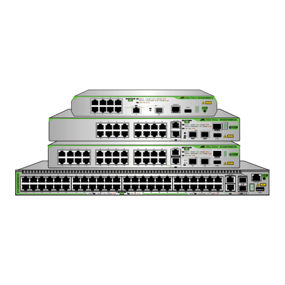
Chapter 1: Overview Front and Back Panels Figure 1 shows the front panel of the GS970EMX/10 Switch. E. One USB Flash Drive A. Eight 10/100/1000Mbps Port Copper Ports F. Switch ID LED B. One 1/2.5/5/10Gbps Multi-Gigabit Copper Port G. eco-friendly Button C. -
Page 21: Figure 3: Front Panel Of The Gs970Emx/28 Switch
CentreCOM GS970EMX Series Installation Guide for Virtual Chassis Stacking Figure 3 shows the front panel of the GS970EMX/28 Switch. E. One Local Management A. Twenty-four 10/100/ Console Port 1000Mbps Copper Ports F. Switch ID LED B. Two 1/2.5/5/10Gbps Multi-Gigabit Copper Ports G. -
Page 22: Figure 5: Back Panels
Chapter 1: Overview Figure 5 illustrates the back panels. GS970EMX/10 Switch GS970EMX/20 and GS970EMX/28 Switches GS970EMX/52 Switch Figure 5. Back Panels Note The GS970EMX/10, GS970EMX/20, and GS970EMX/28 Switches are fanless. The GS970EMX/52 Switch has a single fan inside the back panel. Its ventilation direction is from front to back, with the fan drawing air out of the device. -
Page 23: Features
CentreCOM GS970EMX Series Installation Guide for Virtual Chassis Stacking Features 10/100/1000Mbps The basic features of the 10/100/1000Mbps copper ports are listed here: Copper Ports 10Base-T, 100Base-TX, and 1000Base-T compliant IEEE 802.3u Auto-Negotiation compliant Auto-MDI/MDIX 100 meters (328 feet) maximum operating distance ... -
Page 24: Port And System Leds
The ports support full-duplex mode only. Note SFP and SFP+ transceivers are sold separately. Refer to the product’s data sheet on the Allied Telesis website for a list of supported transceivers. Note The switches do not support the 7-meter SP10TW7 direct connect twinax cable. -
Page 25: Energy Savings
CentreCOM GS970EMX Series Installation Guide for Virtual Chassis Stacking Remote HTTP and HTTPS web browser management Command line interface Autonomous Management Framework Vista Manager EX SNMPv1, v2c, and v3 Energy Savings Here are energy saving features: eco-friendly button for turning on and off the port LEDs ... -
Page 26: 10/100/1000Mbps Copper Ports
Chapter 1: Overview 10/100/1000Mbps Copper Ports Table 1 lists the specifications of the 10/100/1000Mbps copper ports. Table 1. Specifications of the 10/100/1000Mbps Copper Ports Feature Description Speeds Port speeds are listed here: - 10Mbps (IEEE802.3 10Base-T) - 100Mbps (IEEE802.3u 100Base-TX) - 1Gbps (IEEE802.3ab 1000Base-T) Speeds are set manually or with IEEE 802.3u Auto-Negotiation. - Page 27 CentreCOM GS970EMX Series Installation Guide for Virtual Chassis Stacking Table 1. Specifications of the 10/100/1000Mbps Copper Ports (Continued) Feature Description Additional Features Additional features are listed here: - 8-pin RJ-45 connectors - Backpressure flow control supported at half- duplex mode - Non-blocking, wire speed supported at all speeds.
-
Page 28: 1/2.5/5/10Gbps Multi-Gigabit Copper Ports
Chapter 1: Overview 1/2.5/5/10Gbps Multi-Gigabit Copper Ports The GS970EMX/10 Switch has one Multi-Gigabit copper port. The GS970EMX/20, GS970EMX/28, and GS970EMX/52 Switches have two Multi-Gigabit copper ports. Table 2 lists the port specifications. Table 2. Specifications of the 1/2.5/5/10Gbps Multi-Gigabit Copper Ports Specification Description Port Speed... - Page 29 CentreCOM GS970EMX Series Installation Guide for Virtual Chassis Stacking Table 2. Specifications of the 1/2.5/5/10Gbps Multi-Gigabit Copper Ports Specification Description Additional Features Additional features are listed here: - 8-pin RJ-45 connectors - Non-blocking, wire speed supported at all speeds - Supports up to 12KB jumbo frames at 1/ 5/10Gbps - Supports up to 10KB jumbo frames at 2.5Gbps...
-
Page 30: Sfp+ Ports
Chapter 1: Overview SFP+ Ports The GS970EMX/10 Switch has one SFP+ port. The GS970EMX/20, GS970EMX/28, and GS970EMX/52 Switches have two SFP+ ports. The ports support the following types of 1Gbps SFP and 10Gbps SFP+ transceivers: 1Gbps SFP 1000Base-SX/LX transceivers 1Gbps SFP 1000Base-LX single-port BiDi transceivers ... -
Page 31: Port Leds
CentreCOM GS970EMX Series Installation Guide for Virtual Chassis Stacking Port LEDs This section describes the LEDs on the copper, Multi-Gigabit, and SFP+ port. 10/100/1000Mbps The 10/100/1000Mbps copper ports have two LEDs that display the following information: Copper Port LEDs Speed/activity ... - Page 32 Chapter 1: Overview Table 3. Speed/Activity LEDs for the 10/100/1000Mbps Copper Ports State Description Possible causes of this state are listed here: - The port has not established a link with another network device. - The LEDs are turned off. To turn on the LEDs, use the eco-friendly button.
-
Page 33: 1/2.5/5/10Gbps Multi-Gigabit Copper Port Leds
CentreCOM GS970EMX Series Installation Guide for Virtual Chassis Stacking 1/2.5/5/10Gbps The 1/2.5/5/10Gbps Multi-Gigabit copper ports have two LEDs that display speed/activity information. Refer to Figure 7. Multi-Gigabit Copper Port LEDs 1Gbps 2.5/5/10Gbps GS970EMX/10 Switch 1Gbps 2.5/5/10Gbps 1Gbps 2.5/5/10Gbps GS970EMX/20, GS970EMX/28, and GS970EMX/52 Switches Figure 7. -
Page 34: 1/10Gbps Sfp+ Port Leds
Chapter 1: Overview Table 5. Speed/Activity LEDs for the 1/2.5/5/10Gbps Multi-Gigabit Copper Ports (Continued) State Description Possible causes of this state are listed here: - The port has not established a link with another network device. - The LEDs are turned off. To turn on the LEDs, use the eco-friendly button. - Page 35 CentreCOM GS970EMX Series Installation Guide for Virtual Chassis Stacking Table 6 describes the LED. Table 6. Speed/Activity LEDs for the 1/10Gbps SFP+ Ports State Description Solid Amber The port has established a link at 1Gbps to a network device. Flashing Amber The port is transmitting or receiving data at 1Gbps.
-
Page 36: Eco-Friendly Button
Chapter 1: Overview eco-friendly Button You use the eco-friendly button on the front panel of the switch to toggle the port LEDs on and off. You can conserve electricity by turning off the LEDs when you are not monitoring the device. When the LEDs are turned off, the switch is operating in the low power eco-friendly mode. -
Page 37: Switch Id Led
CentreCOM GS970EMX Series Installation Guide for Virtual Chassis Stacking Switch ID LED The Switch ID LED, shown in Figure 9, is for the VCStack feature for the GS970EMX/20, GS970EMX/28, and GS970EMX/52 Switches. You can manage up to four switches as a single unit. This simplifies network management and allows you to add redundancy to your network topology by distributing functions across multiple switches. -
Page 38: Figure 11: Switch Id Led With Eco-Friendly Mode On (Port Leds Off)
Chapter 1: Overview Note The GS970EMX/10 Switch does not support the VCStack feature. It operates as a standalone device with the Switch ID “0”. Note If the Switch ID LED displays “F” for a fault condition, use the SHOW SYSTEM ENVIRONMENT command in the command line interface of the AlliedWare Plus management software to identify the source of the problem. -
Page 39: Usb Port
CentreCOM GS970EMX Series Installation Guide for Virtual Chassis Stacking USB Port You can use the USB port to store configuration files on flash drives to maintain a history of the switch’s configurations, or to restore configuration files to the switch. You can also use the port and flash drives to quickly configure replacement units and update the AlliedWare Plus management software. -
Page 40: Console Port
USB-to-Serial converter that is compatible with its operating system. An example is the VT-Kit3 from Allied Telesis. The Console port pinouts are provided in “RJ-45 Style Serial Console Port Pinouts” on page 174. For further information, refer to “Starting a Local... -
Page 41: Power Supply And Power Savings Features
CentreCOM GS970EMX Series Installation Guide for Virtual Chassis Stacking Power Supply and Power Savings Features The switches have one internal power supply. The power supply is not field-replaceable. Refer to “Power Specifications” on page 169 for the input voltage ranges. Warning Power cord is used as a disconnection device. - Page 42 Chapter 1: Overview...
-
Page 43: Chapter 2: Virtual Chassis Stacking
For more information on VCStack, refer to the Stacking Introduction and Stacking Commands chapters in the Software Reference for GS970EMX Series Switches, AlliedWare Plus Operating System or the Virtual Chassis Stacking Feature Overview and Configuration Guide on the Allied Telesis website. -
Page 44: Overview
Chapter 2: Virtual Chassis Stacking Overview The Virtual Chassis Stacking (VCStack) feature allows you connect up to four GS970EMX/20 , GS970EMX/28, and GS970EMX/52 Switches into a virtual stack so that they function as a single networking unit. Here are some of the VCStack benefits: Simplifies management - You can manage the devices as a single ... -
Page 45: Stacking Guidelines
CentreCOM GS970EMX Series Installation Guide for Virtual Chassis Stacking Stacking Guidelines Here are general VCStack guidelines: A stack can have up to four GS970EMX Switches. The switches can be the same or different GS970EMX Switch models. VCStack comes standard with the AlliedWare Plus management ... -
Page 46: Stack Trunks
The GS970EMX Switches do not support the 7-meter SP10TW7 cable. The fiber optic transceivers or direct attach cables for the trunk must be from Allied Telesis. For a list of supported transceivers, refer to the product’s data sheet on the Allied Telesis web site. -
Page 47: Figure 12: Stack Trunks Of Sfp+ Ports S1 And S2 For Two Switches
CentreCOM GS970EMX Series Installation Guide for Virtual Chassis Stacking Figure 12 to Figure 14 on page 48 illustrate several cabling examples of the SFP+ ports S1 and S2 as the trunk for stacks of two, three, and four switches. As illustrated, the trunk cables can crossover to different SFP+ ports S1 and S2 on the switches or connect the same ports. -
Page 48: Figure 14: Stack Trunks Of Sfp+ Ports S1 And S2 For Four Switches
Chapter 2: Virtual Chassis Stacking Straight-through Crossover Figure 14. Stack Trunks of SFP+ Ports S1 and S2 for Four Switches Stacks can have combinations of GS970EMX/20, GS970EMX/28, and GS970EMX/52 Switches. The stack in Figure 15 has two GS970EMX/20 Switches (top), one GS970EMX/28 Switch, and one GS970EMX/52 Switch (bottom). -
Page 49: Multi-Gigabit Copper Ports
The switches support the linear or chain configuration for the trunk, where the top and bottom switches are not linked together. Refer to Figure 16 for an example. Allied Telesis does not recommend this configuration because it does not provide redundancy should a trunk link fail. -
Page 50: Figure 18: Stack Trunks Of Multi-Gigabit Copper Ports For Three Switches
Chapter 2: Virtual Chassis Stacking Straight-through Crossover Figure 18. Stack Trunks of Multi-Gigabit Copper Ports for Three Switches Crossover Straight-through Figure 19. Stack Trunks of Multi-Gigabit Copper Ports for Four Switches As with the SFP+ ports S1 and S2, the Multi-Gigabit copper ports support the chain topology, where ports on the top and bottom switches are unused. -
Page 51: Unsupported Trunks
CentreCOM GS970EMX Series Installation Guide for Virtual Chassis Stacking Figure 20. Chain Stack Trunk of Multi-Gigabit Copper Ports Unsupported The following examples illustrate unsupported trunks: Trunks Trunks cannot have both Multi-Gigabit copper ports and SFP+ ports S1 and S2. Refer to Figure 21. Figure 21. -
Page 52: Figure 22: Unsupported Trunk Of Sfp+ Ports S1 And S2 With Mixed Cables
Chapter 2: Virtual Chassis Stacking The cables of a stack trunk of the SFP+ ports S1 and S2 can be either fiber optic or direct attach cables, but not both. The trunk in Figure 22 is unsupported because it has both fiber optic and direct attach cables. -
Page 53: Figure 23: Unsupported Trunk With A Network Device Between Trunk Ports
CentreCOM GS970EMX Series Installation Guide for Virtual Chassis Stacking Building 1 Media Converter Building 2 Figure 23. Unsupported Trunk with a Network Device Between Trunk Ports... -
Page 54: Master And Member Switches
Chapter 2: Virtual Chassis Stacking Master and Member Switches Stacks have a master switch. It coordinates and monitors stack operations, and assigns switch ID numbers during the initial formation of the stack and when new switches are added. The other switches of the stack are referred to as member switches. -
Page 55: Switch Id Numbers
CentreCOM GS970EMX Series Installation Guide for Virtual Chassis Stacking Switch ID Numbers Each switch in the stack must have an ID number. The range is 1 to 4. The default is 1. The ID numbers are displayed on the ID LEDs on the front panels of the units. -
Page 56: Feature Licenses
The switches might have additional features that are unlocked with feature licenses from Allied Telesis. Refer to the product’s data sheet on the Allied Telesis website for a list of feature licenses. Here are feature license guidelines: VCStack is part of the base features of GS970EMX Switches. It ... -
Page 57: Planning The Stack
CentreCOM GS970EMX Series Installation Guide for Virtual Chassis Stacking Planning the Stack Here are questions to answer before building the stack: How many switches will be in the stack? Stacks can have one master switch and up to three member switches. Will you use the SFP+ ports or Multi-Gigabit copper ports for the ... -
Page 58: Specifying Ports In The Command Line Interface
Chapter 2: Virtual Chassis Stacking Specifying Ports in the Command Line Interface The ports on the switches of the stack are specified in the AlliedWare Plus command line interface with the PORT parameter. The format of the parameter is shown in Figure 24. port n.n.n Stack ID Module ID... - Page 59 CentreCOM GS970EMX Series Installation Guide for Virtual Chassis Stacking This example enters the Port Interface mode for ports 1 and 2 on a switch with the ID number 3: awplus> enable awplus# configure terminal awplus(config)# interface port3.0.1-port3.0.2 For instructions on the AlliedWare Plus command line interface and the PORT parameter, refer to the Software Reference for GS970EMX Series Switches, AlliedWare Operating System.
-
Page 60: Vcstack Worksheet
Chapter 2: Virtual Chassis Stacking VCStack Worksheet The worksheet in Table 8 is provided to assist you in building and maintaining a stack. Table 8. VCStack Worksheet Firmware Trunk Ports: Model/ Switch Prior- Transceivers in Version Switch SFP+ or Multi- Location SFP+ Ports Gigabit Copper... - Page 61 MAC address. Allied Telesis recommends setting each switch’s priority value to match its ID value. This can protect the stack’s configuration if you later add more switches to an existing stack. It can also...
- Page 62 Chapter 2: Virtual Chassis Stacking Table 9. Stacking Worksheet Columns (Continued) Column Description Firmware Version Use this column to record the version numbers of Number the AlliedWare Plus software on the switches. Switches might not form the stack if they have different versions.
- Page 63 CentreCOM GS970EMX Series Installation Guide for Virtual Chassis Stacking The worksheet in Table 11 documents a stack of one GS970EMX/20 Switch, one GS970EMX/28 Switch, and two GS970EMX/52 Switches. They use the Multi-Gigabit copper ports for the stack trunk. The SFP+ ports are used for other functions, such as attaching high-speed devices to the network with fiber optic cables over long or short distances.
- Page 64 Chapter 2: Virtual Chassis Stacking...
-
Page 65: Chapter 3: Beginning The Installation
Chapter 3 Beginning the Installation The chapter contains the following sections: “Reviewing Safety Precautions” on page 66 “Choosing a Site for the Switch” on page 70 “Unpacking the Switch” on page 72 “Installation Options” on page 75 ... -
Page 66: Reviewing Safety Precautions
Chapter 3: Beginning the Installation Reviewing Safety Precautions Review the following safety precautions before beginning the installation procedure. Note Safety statements that have the symbol are translated into multiple languages in the Translated Safety Statements document at www.alliedtelesis.com/en/documents/translated-safety- statements. Note Les consignes de sécurité... - Page 67 CentreCOM GS970EMX Series Installation Guide for Virtual Chassis Stacking Warning Power cord is used as a disconnection device. To de-energize equipment, disconnect the power cord. Warning Class I Equipment. This equipment must be earthed. The power plug must be connected to a properly wired earth ground socket outlet.
- Page 68 Use dedicated power circuits or power conditioners to supply reliable electrical power to the device. Caution The chassis may be heavy and awkward to lift. Allied Telesis recommends that you get assistance when mounting the chassis in an equipment rack. ...
- Page 69 CentreCOM GS970EMX Series Installation Guide for Virtual Chassis Stacking Caution The unit does not contain serviceable components. Please return damaged units for servicing. Warning The temperature of an active SFP transceiver may exceed 40° C (158° F). Exercise caution when handling with unprotected hands. ...
-
Page 70: Choosing A Site For The Switch
Chapter 3: Beginning the Installation Choosing a Site for the Switch Site and enclosure requirements are described in the following sections: “Site Requirements,” next “Enclosure Requirements” on page 71 Site Observe these site requirements when planning the installation. Requirements The GS970EMX/20 and GS970EMX/28 Switches are fanless. -
Page 71: Enclosure Requirements
If the product overheats in an enclosure that was selected without taking into account these factors, the warranty of the product might be voided. Consult Allied Telesis when assistance is needed. The enclosure’s BTU/hour rating must be higher than the total ... -
Page 72: Unpacking The Switch
Four bumper feet Four M3x4.5 screws for the bumper feet Figure 25. Accessory Items Included with the GS970EMX/20 Switch Note Please retain the original packaging material in the event you need to return the unit to Allied Telesis. -
Page 73: Figure 26: Accessory Items Included With The Gs970Emx/28 Switch
CentreCOM GS970EMX Series Installation Guide for Virtual Chassis Stacking The GS970EMX/28 Switch comes with the accessory items in Figure 26. One management cable, with RJ-45 (8P8C) and DB-9 (D-sub 9-pin) connectors. One AC power cord One power cord retainer clip Four bumper feet Four M3x4.5 screws for the bumper feet... -
Page 74: Figure 27: Accessory Items Included With The Gs970Emx/52 Switch
Two wall/equipment rack brackets Eight 3x6mm Phillips-head screws for attaching the brackets to the switch Figure 27. Accessory Items Included with the GS970EMX/52 Switch Note If any item is missing or damaged, contact your Allied Telesis sales representative for assistance. -
Page 75: Installation Options
CentreCOM GS970EMX Series Installation Guide for Virtual Chassis Stacking Installation Options The following sections illustrate the installation options for the switches. GS970EMX/20 Figure 28 illustrates the installation options for the GS970EMX/20 Switch. Switch Table or desktop with the bumper feet included with the switch. Standard 19-inch equipment rack with the RKMT-J13 equipment rack brackets kit. -
Page 76: Gs970Emx/28 Switch
Chapter 3: Beginning the Installation GS970EMX/28 Figure 28 illustrates the installation options for the GS970EMX/28 Switch. Switch Table or desktop with the bumper feet included with the switch. Standard 19-inch equipment rack with the equipment rack brackets included with the switch, or the RKMT-J13 equipment rack brackets kit. -
Page 77: Gs970Emx/52 Switch
CentreCOM GS970EMX Series Installation Guide for Virtual Chassis Stacking GS970EMX/52 Figure 30 illustrates the installation options for the GS970EMX/52 Switch. Switch Table or desktop with the bumper feet included with the switch. Standard 19-inch equipment rack with the wall/equipment rack brackets included with the switch. -
Page 78: Hardware Options
Chapter 3: Beginning the Installation Hardware Options The following hardware options for the GS970EMX/20 and GS970EMX/28 Switches are sold separately. Note The GS970EMX/52 Switch does not require the hardware options. RKMT-J13 Installing the GS970EMX/20 Switch in a standard 19-inch equipment rack requires the RKMT-J13 brackets kit. -
Page 79: Brkt-J24 Wall Brackets Kit
CentreCOM GS970EMX Series Installation Guide for Virtual Chassis Stacking Note The GS970EMX/28 and GS970EMX/52 Switches come with brackets for equipment rack installations. BRKT-J24 Wall Installing the GS970EMX/20 and GS970EMX/28 Switches on a wall requires the BRKT-J24 wall brackets kit. Refer to Figure 32. For Brackets Kit instructions, refer to Chapter 7, “Installing GS970EMX/20, GS970EMX/28, and GS970EMX/52 Switches on a Wall”... -
Page 80: Recording The Serial Number And Mac Address
Chapter 3: Beginning the Installation Recording the Serial Number and MAC Address The serial number and MAC address of the switch are located on labels on the bottom panel. Refer to Figure 33. If you need to record the numbers for your records, you should do so before installing the device. -
Page 81: Installing The Switch On A Table
CentreCOM GS970EMX Series Installation Guide for Virtual Chassis Stacking Installing the Switch on a Table You can operate the switch on a table or desktop. Refer to Figure 34. Figure 34. Switch Installation on a Table The following guidelines are in addition to those in “Choosing a Site for the Switch”... -
Page 82: Figure 36: Attaching The Bumper Feet
Chapter 3: Beginning the Installation Note Bumper feet are required for tabletop installation. They promote cooling by allowing airflow beneath the switch. To install the switch on a table, perform the following procedure: 1. Verify that the selected site is suitable for the unit by reviewing “Reviewing Safety Precautions”... -
Page 83: Figure 37: Attaching Bumper Feet On The Gs970Emx/52 Switch
CentreCOM GS970EMX Series Installation Guide for Virtual Chassis Stacking Figure 37. Attaching Bumper Feet on the GS970EMX/52 Switch 7. Turn the switch over, placing it on the bumper feet. 8. Go to Chapter 8, “Displaying the Hardware Status and AlliedWare Plus Version Number”... - Page 84 Chapter 3: Beginning the Installation...
-
Page 85: Chapter 4: Installing The Gs970Emx/20 Switch In An Equipment Rack
Chapter 4 Installing the GS970EMX/20 Switch in an Equipment Rack This chapter contains the installation instructions for the GS970EMX/20 Switch in a standard 19-inch equipment rack with the RKMT-J13 equipment rack brackets kit. Here are the sections in the chapter: “Introduction”... -
Page 86: Introduction
Chapter 4: Installing the GS970EMX/20 Switch in an Equipment Rack Introduction Installing the GS970EMX/20 Switch in a standard 19-inch equipment rack requires the RKMT-J13 equipment rack brackets kit. The kit allows you to install the switch with its front panel flush with or recessed 50mm (2 in.) behind the front of the equipment rack. -
Page 87: Installing The Gs970Emx/20 Switch
CentreCOM GS970EMX Series Installation Guide for Virtual Chassis Stacking Installing the GS970EMX/20 Switch This section contains the procedure for installing the GS970EMX/20 Switch in standard 19-inch equipment rack with the RKMT-J13 equipment rack brackets kit. Here are the required items: One RKMT-J13 equipment rack brackets kit. -
Page 88: Figure 40: Attaching The Extenders To The Rkmt-J13 Brackets
Chapter 4: Installing the GS970EMX/20 Switch in an Equipment Rack Figure 40. Attaching the Extenders to the RKMT-J13 Brackets 5. Attach the brackets to the sides of the switch with six of the 4x8mm screws included in the kit. Refer to Figure 41. Figure 41. -
Page 89: Figure 42: Securing The Gs970Emx/20 Switch In A Standard 19-Inch Equipment Rack
CentreCOM GS970EMX Series Installation Guide for Virtual Chassis Stacking 6. Have another person hold the switch at the selected location in the equipment rack while you secure it using four standard equipment rack screws (not provided). Refer to Figure 42. Figure 42. - Page 90 Chapter 4: Installing the GS970EMX/20 Switch in an Equipment Rack...
-
Page 91: Chapter 5: Installing The Gs970Emx/28 Switch In An Equipment Rack
Chapter 5 Installing the GS970EMX/28 Switch in an Equipment Rack This chapter contains the installation instructions for the GS970EMX/28 Switch in a standard 19-inch equipment rack. Here are the sections: “Introduction” on page 92 “Installing the GS970EMX/28 Switch” on page 93 ... -
Page 92: Introduction
Chapter 5: Installing the GS970EMX/28 Switch in an Equipment Rack Introduction The GS970EMX/28 Switch comes with two brackets for installing the device in a standard 19-inch equipment rack. Refer to Figure 43. The brackets and screws are shown in Figure 26 on page 73. Figure 43. -
Page 93: Installing The Gs970Emx/28 Switch
CentreCOM GS970EMX Series Installation Guide for Virtual Chassis Stacking Installing the GS970EMX/28 Switch This section contains the procedure for installing the GS970EMX/28 Switch in a standard 19-inch equipment rack with the two equipment rack brackets included with the device. Here are the required items: Two equipment rack brackets (included with the switch). -
Page 94: Figure 45: Securing The Gs970Emx/28 Switch In A Standard 19-Inch Equipment Rack
Chapter 5: Installing the GS970EMX/28 Switch in an Equipment Rack Figure 45. Securing the GS970EMX/28 Switch in a Standard 19-inch Equipment Rack... -
Page 95: Chapter 6: Installing The Gs970Emx/52 Switch In An Equipment Rack
Chapter 6 Installing the GS970EMX/52 Switch in an Equipment Rack This chapter contains the installation instructions for the GS970EMX/52 Switch in a standard 19-inch equipment rack. Here are the sections: “Introduction” on page 96 “Installing the GS970EMX/52 Switch” on page 97 ... -
Page 96: Introduction
Chapter 6: Installing the GS970EMX/52 Switch in an Equipment Rack Introduction The GS970EMX/52 Switch comes with two brackets and eight screws for installing the device in a standard 19-inch equipment rack. Refer to Figure 27 on page 74. The switch has two sets of four screw holes on the left and right sides for the brackets. -
Page 97: Installing The Gs970Emx/52 Switch
GS970EMX Series Installation Guide for Standalone Switches Installing the GS970EMX/52 Switch This section contains the procedure for installing the GS970EMX/52 Switch in a standard 19-inch equipment rack. Here are the required items: Two wall/equipment rack brackets (included with the switch). ... -
Page 98: Figure 49: Securing The Gs970Emx/52 Switch In A Standard 19-Inch Equipment Rack
Chapter 6: Installing the GS970EMX/52 Switch in an Equipment Rack 3. Have another person hold the switch at the selected location in the equipment rack while you secure it using four standard equipment rack screws (not provided). Refer to Figure 49. Figure 49. - Page 99 Chapter 7 Installing GS970EMX/20, GS970EMX/28, and GS970EMX/52 Switches on a Wall This chapter contains instructions for installing GS970EMX/20, GS970EMX/28, and GS970EMX/52 Switches on a wood or concrete wall. The chapter contains the following sections: “Installation Guidelines” on page 100 “Plywood Base for a Wall with Wooden Studs”...
-
Page 100: Chapter 7: Installing Gs970Emx/20, Gs970Emx/28, And Gs970Emx/52 Switches On A Wall
Chapter 7: Installing GS970EMX/20, GS970EMX/28, and GS970EMX/52 Switches on a Wall Installation Guidelines The guidelines to installing GS970EMX/20, GS970EMX/28, and GS970EMX/52 Switches on a wall are listed here: The GS970EMX/20 and GS970EMX/28 Switches require the BRKT-J24 wall brackets kit for wall installations. The kit comes with four identical brackets. -
Page 101: Figure 52: Unsupported Wall Installation Of The Gs970Emx/20, Gs970Emx/28, And Gs970Emx/52 Switches
CentreCOM GS970EMX Series Installation Guide for Standalone Switches Do not install switches with the front panels facing down. Refer to Figure 52. Figure 52. Unsupported Wall Installation of the GS970EMX/20, GS970EMX/28, and GS970EMX/52 Switches Here are the guidelines to installing switches on a wall: You may install the switches on wooden or concrete walls. - Page 102 Chapter 7: Installing GS970EMX/20, GS970EMX/28, and GS970EMX/52 Switches on a Wall Here are the required tools and material for installing the switch on a wall: For GS970EMX/20 and GS970EMX/28 Switches, one BRKT-J24 wall brackets kit for each switch. The kit is sold separately. For the GS970EMX/52 Switch, two wall//equipment rack brackets ...
-
Page 103: Plywood Base For A Wall With Wooden Studs
CentreCOM GS970EMX Series Installation Guide for Standalone Switches Plywood Base for a Wall with Wooden Studs When installing the switch on a wall that has wooden studs, Allied Telesis recommends installing the device on a plywood base. (A plywood base is not required for concrete walls.) Refer to Figure 53. -
Page 104: Figure 54: Steps To Installing Gs970Emx Switches On A Plywood Base
Chapter 7: Installing GS970EMX/20, GS970EMX/28, and GS970EMX/52 Switches on a Wall Recommended minimum dimensions of a plywood base for the GS970EMX/52 Switch are listed here: Width: 55.9 centimeters (22 inches) Height: 50 centimeters (22 inches) Thickness: 2.5 centimeters (1 inch) ... -
Page 105: Installing The Switch
Review “Reviewing Safety Precautions” on page 66 and “Choosing a Site for the Switch” on page 70 before performing this procedure. Allied Telesis recommends a minimum of two people for this procedure. Warning The device is heavy. Always ask for assistance before moving or lifting it to avoid injuring yourself or damaging the equipment. -
Page 106: Figure 55: Attaching The Brkt-J24 Wall Brackets To The Gs970Emx/20 And Gs970Emx/28 Switches
Chapter 7: Installing GS970EMX/20, GS970EMX/28, and GS970EMX/52 Switches on a Wall Figure 55. Attaching the BRKT-J24 Wall Brackets to the GS970EMX/20 and GS970EMX/28 Switches 3. For the GS970EMX/52 Switch, attach the two wall/equipment rack brackets to one side of the switch. Refer to Figure 56 and Figure 57 on page 107. -
Page 107: Figure 57: Attaching The Wall/Equipment Rack Brackets To The Gs970Emx/52 Switch (Continued)
CentreCOM GS970EMX Series Installation Guide for Standalone Switches Figure 57. Attaching the Wall/Equipment Rack Brackets to the GS970EMX/52 Switch (continued) Note If the wall requires pre-drilled holes, such as a concrete wall, continue with the next steep. Otherwise, go to step 8. 4. -
Page 108: Figure 58: Marking The Locations Of The Bracket Holes
For concrete walls, set the drill to hammer and rotation mode. The modes break up the concrete and clean out the hole. Allied Telesis recommends cleaning out the holes with a brush or compressed air. 7. If the wall material requires anchors, insert appropriate anchors in the holes. -
Page 109: Chapter 8: Displaying The Hardware Status And Alliedware Plus Version Number
Chapter 8 Displaying the Hardware Status and AlliedWare Plus Version Number The procedures in this chapter explain how to perform local management sessions on the switches to verify their hardware status and display the version numbers of the AlliedWare Plus management software. Allied Telesis recommends performing these procedures on each switch individually before building the stack. -
Page 110: Powering On The Switch
Chapter 8: Displaying the Hardware Status and AlliedWare Plus Version Number Powering On the Switch The illustrations in this procedure show the North American power cord. Your power cord may look different. For AC power specifications, refer to “Power Specifications” on page 169. Warning Power cord is used as a disconnection device. -
Page 111: Figure 61: Lowering The Power Cord Retaining Clip
CentreCOM GS970EMX Series Installation Guide for Virtual Chassis Stacking 3. Lower the retaining clip to secure the power cord to the switch. Refer to Figure 61. Figure 61. Lowering the Power Cord Retaining Clip 4. Connect the power cord to an appropriate AC power outlet. Refer to Figure 62. -
Page 112: Starting A Local Management Session
If your computer has a USB port, you may need to purchase a USB-to-Serial converter that is compatible with its operating system. An example is the VT-Kit3 converter from Allied Telesis, shown in Figure 64. The VT-Kit3 converter is sold separately. Figure 64. VT-Kit3 Management Cable Local management sessions do not interfere with the network ... -
Page 113: Figure 65: Local Management With The Vt-Kit3 Management Cable
If your computer has a USB port, use a USB-to-Serial converter. To use the VT-Kit3 from Allied Telesis, connect the USB connector on the VT-Kit3 to a USB port on your computer or terminal. To connect the kit to the Console port on the switch, use a standard, straight-through Ethernet cable. - Page 114 Chapter 8: Displaying the Hardware Status and AlliedWare Plus Version Number Note The baud rate must be set to the default 9600 bps to configure the boot loader. 4. Press Enter. You are prompted for the name and password of the manager account.
-
Page 115: Displaying The Hardware Status And Alliedware Plus Version Number
CentreCOM GS970EMX Series Installation Guide for Virtual Chassis Stacking Displaying the Hardware Status and AlliedWare Plus Version Number This section contains the procedure for displaying the version number of the AlliedWare Plus management software on the switch. All of the switches in a stack must have the same version of the management software. - Page 116 Chapter 8: Displaying the Hardware Status and AlliedWare Plus Version Number Warning Power cord is used as a disconnection device. To de-energize equipment, disconnect the power cord. E3 9. Repeat the procedures in this chapter on the remaining switches that will be in the stack.
-
Page 117: Chapter 9: Building Stacks With Sfp+ Ports S1 And S2
Chapter 9 Building Stacks with SFP+ Ports S1 and This chapter contains the following procedures: “Introduction” on page 118 “Powering On the Switches Sequentially” on page 119 “Powering On the Switches Simultaneously” on page 121 “Verifying the Stack and Assigning Priority Numbers” on page 123 ... -
Page 118: Introduction
Chapter 9: Building Stacks with SFP+ Ports S1 and S2 Introduction This chapter explains how to build the stack with SFP+ ports S1 and S2 as the stack trunk. There are no configuration procedures. The stacking feature is enabled by default on the switches and the SFP+ ports are the default trunk ports. -
Page 119: Powering On The Switches Sequentially
CentreCOM GS970EMX Series Installation Guide for Virtual Chassis Stacking Powering On the Switches Sequentially This procedure explains how to control the assignment of the switch ID numbers by powering on the units one at a time during the first power-on sequence. - Page 120 Chapter 9: Building Stacks with SFP+ Ports S1 and S2 Warning Power cord is used as a disconnection device. To de-energize equipment, disconnect the power cord. E3 3. Wait one minute for the switch to start the AlliedWare Plus management software.
-
Page 121: Powering On The Switches Simultaneously
CentreCOM GS970EMX Series Installation Guide for Virtual Chassis Stacking Powering On the Switches Simultaneously You can let the switches assign their ID numbers automatically by powering them on simultaneously during the first power-on sequence. They perform the following steps when assigning their ID numbers: 1. - Page 122 Chapter 9: Building Stacks with SFP+ Ports S1 and S2 2. Power on all the switches of the stack simultaneously. Refer to “Powering On the Switch” on page 110. Warning Power cord is used as a disconnection device. To de-energize equipment, disconnect the power cord.
-
Page 123: Verifying The Stack And Assigning Priority Numbers
CentreCOM GS970EMX Series Installation Guide for Virtual Chassis Stacking Verifying the Stack and Assigning Priority Numbers To verify the stack and assign priority numbers, perform the following procedure: 1. Start a local management session on any switch in the stack. For instructions, refer to “Starting a Local Management Session”... -
Page 124: Figure 68: Moving To The Global Configuration Mode With The Enable And Configure Terminal Commands
Chapter 9: Building Stacks with SFP+ Ports S1 and S2 3. Do one of the following: To set the switch priority values, continue with the next step. Setting the priority values is optional. For background information, refer to the “STACK PRIORITY Command” on page 130. Otherwise, go to Chapter 11, “Cabling Copper and SFP+ Ports”... -
Page 125: Figure 69: Returning To The Privileged Exec Mode
CentreCOM GS970EMX Series Installation Guide for Virtual Chassis Stacking To assign the priority value to 2 to the switch with the ID number 2, you enter: awplus(config)# stack 2 priority 2 6. After setting the priority values, enter the EXIT command to return to the Privileged Exec mode. - Page 126 Chapter 9: Building Stacks with SFP+ Ports S1 and S2...
-
Page 127: Chapter 10: Building Stacks With Multi-Gigabit Copper Ports
Chapter 10 Building Stacks with Multi-Gigabit Copper Ports This chapter contains the following sections: “Introduction” on page 128 “Command Summary” on page 129 “Configuring the Master Switch” on page 133 “Configuring Member Switches” on page 141 “Powering On the Stack”... -
Page 128: Introduction
Chapter 10: Building Stacks with Multi-Gigabit Copper Ports Introduction As explained in “Stack Trunks” on page 46, the switches of a stack are connected by a physical link of two ports on each unit. There are two ways to build the trunk on GS970EMX Switches. One way is with the SFP+ ports S1 and S2, the default trunk ports. -
Page 129: Command Summary
CentreCOM GS970EMX Series Installation Guide for Virtual Chassis Stacking Command Summary This section describes the AlliedWare Plus commands for configuring the Multi-Gigabit copper ports as the stack trunk on the master and member switches. For further instructions, refer to the Software Reference for GS970EMX Switch, AlliedWare Plus Operating System. -
Page 130: Stack Priority Command
The lower the MAC address, the higher the priority. Allied Telesis recommends setting the priority numbers to match the switch ID numbers. For example, the switch with ID 1 should be assigned priority 1, switch with ID 2 should be assigned priority 2, and so on. This is not a requirement, but it can make it easier to manage the stack. -
Page 131: Stack Renumber Command
CentreCOM GS970EMX Series Installation Guide for Virtual Chassis Stacking This example assigns the priority 1 to the switch with ID 1: awplus(config)# stack 1 priority 1 This example assigns the priority 2 to the switch with ID 2: awplus(config)# stack 2 priority 2 STACK Every switch in the stack must have a unique ID number. -
Page 132: Switch Provision Command
Chapter 10: Building Stacks with Multi-Gigabit Copper Ports SWITCH You use this command to add member switches to the configuration of the master switch before powering on the stack for the first time. Here are the PROVISION command guidelines: Command Adding member switches to the master switch is not required when ... -
Page 133: Configuring The Master Switch
Note The procedures require reseting the switch. Some network traffic will be lost if its ports are already connected to active devices. Allied Telesis recommends filling out the “VCStack Worksheet” on page 60 before building the stack. General Steps for There are two parts to designating the Multi-Gigabit copper ports on the master switch as the stack trunk. -
Page 134: Configuring The Master Switch - Part I
Chapter 10: Building Stacks with Multi-Gigabit Copper Ports Here are the main steps to Part II: 1. Add the member switches as provisioned units to the configuration of the master switch, with the SWITCH PROVISION command. 2. Remove the default SFP+ S1 and S2 ports from the stack trunk on the provisioned member switches with the NO STACKPORT command. - Page 135 CentreCOM GS970EMX Series Installation Guide for Virtual Chassis Stacking Table 12. Configuring the Master Switch for a Stack Trunk of Multi-Gigabit Copper Ports - Part I Step Description and Command Steps 4 and 5 use the NO STACKPORT command to remove the SFP+ S1 and S2 ports from the stack trunk and redefine them as regular networking ports.
-
Page 136: Configuring The Master Switch - Part Ii
Chapter 10: Building Stacks with Multi-Gigabit Copper Ports Table 12. Configuring the Master Switch for a Stack Trunk of Multi-Gigabit Copper Ports - Part I Step Description and Command The remaining steps save your changes. Enter the EXIT command to return to the Privileged Exec mode. awplus(config)# exit Enter the WRITE command to save your changes. - Page 137 CentreCOM GS970EMX Series Installation Guide for Virtual Chassis Stacking Table 13. Configuring the Master Switch for a Stack Trunk of Multi-Gigabit Copper Ports - Part II Step Description and Command Steps 3 and 4 remove the default SFP+ S1 and S2 ports from the trunk on the provisioned member switches that you added in step 2, with the NO STACKPORT command.
-
Page 138: Verifying The Master Switch
Chapter 10: Building Stacks with Multi-Gigabit Copper Ports Table 13. Configuring the Master Switch for a Stack Trunk of Multi-Gigabit Copper Ports - Part II Step Description and Command Restart the switch with the REBOOT command. awplus# reboot reboot system? (y/n): Type “Y”... -
Page 139: Figure 73: Show Running-Config Interface Command On The Master Switch
CentreCOM GS970EMX Series Installation Guide for Virtual Chassis Stacking The Operational Status should be Standalone Unit. This indicates that VCStack is enabled, but that the unit is operating as a stack of one switch. If the status is Stacking Hardware Disabled, VCStack is disabled. -
Page 140: What To Do Next
Chapter 10: Building Stacks with Multi-Gigabit Copper Ports What to Do Next After configuring the master switch, do the following: 1. Power off the switch by disconnecting its AC power cord from the AC power source. Refer to Figure 74. Figure 74. -
Page 141: Configuring Member Switches
CentreCOM GS970EMX Series Installation Guide for Virtual Chassis Stacking Configuring Member Switches This section contains the procedures for designating the Multi-Gigabit copper ports as the stack trunk for the member switches of a stack. Here are the procedures: “General Steps for Member Switches” on page 141 ... -
Page 142: Configuring Member Switches - Part I
Chapter 10: Building Stacks with Multi-Gigabit Copper Ports 5. Restart the switch with the REBOOT command. 6. Start a new local management session. 7. Verify your changes with the SHOW STACK and SHOW RUNNING- CONFIG INTERFACE commands. Configuring Perform the procedure in Table 14 to perform Part I to configure a member switch. -
Page 143: Configuring Member Switches - Part Ii
CentreCOM GS970EMX Series Installation Guide for Virtual Chassis Stacking Table 14. Configuring Member Switches - Part I (Continued) Step Description and Command Restart the switch with the REBOOT command. awplus# reboot reboot system? (y/n): awplus# Type “Y” for yes. Wait one minute for the switch to start the AlliedWare Plus software. Check the ID LED on the front panel. - Page 144 Chapter 10: Building Stacks with Multi-Gigabit Copper Ports Table 15. Configuring Member Switches - Part II (Continued) Step Description and Command Enter the port Interface modes of the SFP+ S1 and S2 ports on the member switch. When specifying the ID number of the switch in the PORT parameter, be sure to use the ID number you assigned it in Part I.
-
Page 145: Verifying Member Switches
CentreCOM GS970EMX Series Installation Guide for Virtual Chassis Stacking Table 15. Configuring Member Switches - Part II (Continued) Step Description and Command Type “Y” for yes. Wait one minute for the switch to start the AlliedWare Plus software. Go to “Verifying Member Switches,” next. Verifying Perform this procedure to verify the configuration of a member switch. -
Page 146: Figure 76: Show Running-Config Interface Command For Member Switches
Chapter 10: Building Stacks with Multi-Gigabit Copper Ports Note The default setting for VCStack is enabled. If VCStack is disabled, perform the STACK ENABLE command in the Global Configuration mode to enable it. 5. Enter the SHOW RUNNING-CONFIG INTERFACE command to display the port configuration on the member switch. -
Page 147: What To Do Next For Member Switches
CentreCOM GS970EMX Series Installation Guide for Virtual Chassis Stacking What to Do Next After configuring a member switch, do the following: for Member 1. Power off the member switch by disconnecting its AC power cord from Switches the AC power source. Refer to Figure 74 on page 140. 2. -
Page 148: Powering On The Stack
Chapter 10: Building Stacks with Multi-Gigabit Copper Ports Powering On the Stack After deswignating the Multi-Gigabit copper ports on the master and member switches as the stack trunk and assigning them ID numbers, you are ready to cable the trunk ports and power on the stack. You can monitor the power-on sequence by connecting a terminal or computer with a terminal emulator program to the Console port on the master switch. -
Page 149: Chapter 11: Cabling Copper And Sfp+ Ports
Chapter 11 Cabling Copper and SFP+ Ports This chapter contains the following sections: “Cabling Copper Ports” on page 150 “Guidelines to Handling SFP and SFP+ Transceivers” on page 151 “Installing 1Gbps SFP and 10Gbps SFP+ Transceivers” on page 152 ... -
Page 150: Cabling Copper Ports
Chapter 11: Cabling Copper and SFP+ Ports Cabling Copper Ports Here are the guidelines to cabling the copper ports: The cable specifications are in “10/100/1000Mbps Copper Ports” on page 26 and “1/2.5/5/10Gbps Multi-Gigabit Copper Ports” on page 28. The connectors on the cables should fit snugly into the ports, and ... -
Page 151: Guidelines To Handling Sfp And Sfp+ Transceivers
For a list of supported transceivers, refer to the product’s data sheet on the Allied Telesis web site. The operational specifications and fiber optic cable requirements of the transceivers are provided in documents included with the devices. -
Page 152: Installing 1Gbps Sfp And 10Gbps Sfp+ Transceivers
1. Select an SFP+ port for the transceiver. 2. Remove the transceiver from its shipping container and store the packaging material in a safe location. 3. Position the transceiver with the Allied Telesis label facing up. Refer to Figure 77. Figure 77. Installing an SFP+ Transceiver 4. -
Page 153: Figure 78: Removing The Dust Cover From An Sfp+ Transceiver
CentreCOM GS970EMX Series Installation Guide for Standalone Switches Figure 78. Removing the Dust Cover from an SFP+ Transceiver 6. Verify that the transceiver handle is in the upright position. Refer to Figure 79. SFP+ Handle Figure 79. Positioning the SFP+ Handle in the Upright Position 7. -
Page 154: Figure 80: Connecting A Fiber Optic Cable To An Sfp Or Sfp+ Transceiver
Chapter 11: Cabling Copper and SFP+ Ports Figure 80. Connecting a Fiber Optic Cable to an SFP or SFP+ Transceiver 8. Repeat this procedure to install a second transceiver. -
Page 155: Installing Sp10Tw Direct Connect Twinax Cables In Sfp+ Ports
1. Select an SFP+ port for the transceiver. 2. Remove the transceiver from its shipping container and store the packaging material in a safe location. 3. Position the transceiver with the Allied Telesis label facing up. Refer to Figure 81. Figure 81. Installing an SP10TW Cable 4. - Page 156 Chapter 11: Cabling Copper and SFP+ Ports 6. Repeat this procedure to install a second transceiver. Note To remove the connector and cable from the port, gently push on the connector, pull on the release tab, and slide the connector from the switch.
-
Page 157: Chapter 12: Troubleshooting
This chapter contains suggestions on how to troubleshoot problems with the switch. Note For further assistance, contact Allied Telesis Technical Support at www.alliedtelesis.com/us/en/services-support. Problem 1: The ports are connected to network devices but the port LEDs and Switch ID LED are off. - Page 158 Chapter 12: Troubleshooting Verify that you are using the appropriate category of cable. Cable requirements are listed in Table 1 on page 26 and Table 2 on page 28. Verify that the port is connected to the correct cable. ...
- Page 159 If the stack trunk consists of the SFP+ S1 and S2 ports, verify that the transceivers are from Allied Telesis. If the stack trunk consists of the SFP+ S1 and S2 ports, verify that the transceivers are fully inserted in the switch ports and that the cables are securely connected to the transceivers.
- Page 160 Chapter 12: Troubleshooting...
-
Page 161: Appendix A: Technical Specifications
Appendix A Technical Specifications This appendix contains the following sections: ”Physical Specifications” on page 162 ”Environmental Specifications” on page 166 ”Power Specifications” on page 169 ”Certifications” on page 171 ”RJ-45 Copper Port Pinouts” on page 173 ... -
Page 162: Physical Specifications
Appendix A: Technical Specifications Physical Specifications Dimensions Table 16 and Figure 82 and Figure 83 on page 163 provide the dimensions of the switches. Table 16. Product Dimensions (H x W x D) GS970EMX/10 3.8 cm x 26.3 cm x 17.9 cm (1.5 in. -
Page 163: Figure 83: Dimensions Of Gs970Emx/20 And Gs970Emx/28 Switches
CentreCOM GS970EMX Series Installation Guide for Virtual Chassis Stacking Width 34.1 cm (13.4 in.) Height 4.4 cm (1.7 in.) Depth 23.1 cm (9.1 in.) Figure 83. Dimensions of GS970EMX/20 and GS970EMX/28 Switches Width 44.1 cm (17.3 in.) Height 4.4 cm (1.7 in.) Depth 32.2 cm (12.7 in.) Figure 84. -
Page 164: Figure 85: Bracket Screw Holes On Gs970Emx/20 And Gs970Emx/28 Switches
Appendix A: Technical Specifications Weights Table 17 lists the switch weights. Table 17. Switch Weights GS970EMX/10 1.6 kg (3.53 lb.) GS970EMX/20 3.0 kg (6.61 lb.) GS970EMX/28 3.1 kg (6.84 lb.) GS970EMX/52 4.5 kg (9.92 lb.) Ventilation Table 18 lists the ventilation requirements. Table 18. -
Page 165: Figure 86: Bracket Screw Holes On The Gs970Emx/52 Switch
CentreCOM GS970EMX Series Installation Guide for Virtual Chassis Stacking Figure 86. Bracket Screw Holes on the GS970EMX/52 Switch... -
Page 166: Environmental Specifications
Appendix A: Technical Specifications Environmental Specifications Table 19 lists the storage and operating environment specifications of the switches. Table 19. Storage and Operating Environment Specifications Storage Temperature -25° C to 70° C (-13° F to 158° F) Operating Humidity 5% to 90% noncondensing Storage Humidity 5% to 95% noncondensing Maximum Operating Altitude... - Page 167 CentreCOM GS970EMX Series Installation Guide for Virtual Chassis Stacking Table 20. Operating Temperature Ranges (Continued) GS970EMX/20 Switch Table, equipment rack, or wall without SFP/SFP+ transceivers Table, equipment rack, or wall with SFP/SFP+ transceivers that have a maximum operating temperature of 85°C (185°F) 0°C to 50°C (32°F to 122°F) Table or horizontal equipment rack...
- Page 168 Appendix A: Technical Specifications Table 20. Operating Temperature Ranges (Continued) Wall with front panel facing right 0° C to 40° C (32° F to 104° F) and with SFP/SFP+ transceivers that have a maximum operating temperature of 70°C (158°F) GS970EMX/52 Switch Table, equipment rack, or wall with 0°...
-
Page 169: Power Specifications
CentreCOM GS970EMX Series Installation Guide for Virtual Chassis Stacking Power Specifications This section contains the maximum power consumption values, input voltages, and heat dissipation values. Maximum Power Consumptions Table 21 lists the maximum power consumptions of the switch. Table 21. Maximum Power Consumption GS970EMX/10 21 watts GS970EMX/20... - Page 170 Appendix A: Technical Specifications Heat Dissipation Table 23 lists the heat dissipation. Table 23. Heat Dissipation GS970EMX/10 71 BTU/hr GS970EMX/20 96 BTU/hr GS970EMX/28 114 BTU/hr GS970EMX/52 181 BTU/hr...
-
Page 171: Certifications
CentreCOM GS970EMX Series Installation Guide for Virtual Chassis Stacking Certifications Table 24 lists the product certificates. Table 24. Product Certifications Additional Certificates CISPR Class A (Comité International Spécial des Perturbations Radioélectriques) Compliant with European and China RoHS standards Australia/New Zealand (Regulatory Compliance Mark) Common Criteria NIAP... - Page 172 Appendix A: Technical Specifications Table 24. Product Certifications (Continued) Mexico (Normas Oficiales Mexicanas) North America FCC Class A Laser Safety: EN 60825-1 Energy Star United Kingdom UKCA (UK Conformity Assessment)
-
Page 173: Copper Port Pinouts
CentreCOM GS970EMX Series Installation Guide for Virtual Chassis Stacking RJ-45 Copper Port Pinouts Figure 87 illustrates the pin layout of the RJ-copper ports. Figure 87. Pin Layout for the RJ-45 Copper Ports (Front View) Table 25 lists the pin signals for the copper ports. Table 25. -
Page 174: Style Serial Console Port Pinouts
Appendix A: Technical Specifications RJ-45 Style Serial Console Port Pinouts Table 26 lists the pin signals of the RJ-45 style serial Console port. Table 26. RJ-45 Style Serial Console Port Pin Signals Signal Unused Unused Transmit Data Signal Ground Signal Ground Receive Data Unused Unused...
Need help?
Do you have a question about the CentreCOM GS970EMX/52 and is the answer not in the manual?
Questions and answers