
Related Manuals for Allied Telesis GS910 Series


Summary of Contents for Allied Telesis GS910 Series
- Page 1 GS910 Series GIGABIT ETHERNET UNMANAGED SWITCHES AT-GS910/5 AT-GS910/5E AT-GS910/8 AT-GS910/8E AT-GS910/16 AT-GS910/24 Installation and User’s Guide 613-002143 Rev. B...
- Page 2 Telesis, Inc. be liable for any incidental, special, indirect, or consequential damages whatsoever, including but not limited to lost profits, arising out of or related to this manual or the information contained herein, even if Allied Telesis, Inc. has been...
- Page 3 Electrical Safety and Emissions Standards This section contains the following: “US Federal Communications Commission” “Industry Canada” “Emissions, Immunity and Electrical Safety Standards” on page 4 “Translated Safety Statements” on page 4 US Federal Communications Commission Radiated Energy Note This equipment has been tested and found to comply with the limits for a Class A digital device pursuant to Part 15 of FCC Rules.
-
Page 4: Translated Safety Statements
EMC (Immunity) EN55024, EN61000-3-2, EN61000-3-3 Electrical Safety UL60950-1 ( ), UL-CB, UL-EU Translated Safety Statements Important: The indicates that translations of the safety statement are available in the PDF document Translated Safety Statements posted on the Allied Telesis website at alliedtelesis.com/support. -
Page 5: Table Of Contents
Contents Preface ....................................7 Safety Symbols Used in this Document ..........................8 Contacting Allied Telesis ..............................9 Chapter 1: Product Description ............................11 Overview ..................................12 AT-GS910/5 Switch..............................12 AT-GS910/5E Switch .............................13 AT-GS910/8 Switch..............................14 AT-GS910/8E Switch .............................14 AT-GS910/16 Switch..............................15 AT-GS910/24 Switch..............................16 Wall and Rack Mount Brackets ..........................16 LEDs ..................................17... - Page 6 Contents Reviewing Safety Precautions ............................52 Unpacking the AT-BRKT-J23 Wall Mount Kit ........................53 Installing a Switch Using the AT-BRKT-J23 Wall Mount Kit ..................54 What to Prepare ..............................54 Installing a Switch Using the Wall Mount Kit ......................54 Chapter 4: Installation Using the AT-RKMT-J08 Rack Mount Kit ..................57 Reviewing Safety Precautions ............................58 Unpacking the AT-RKMT-J08 Rack Mount Kit ......................59 Installing a Switch Using the AT-RKMT-J08 Rack Mount Kit ..................61...
-
Page 7: Preface
Preface This manual is the installation and user’s guide for the GS910 Series Gigabit Ethernet Unmanaged Switches. The switch models included in this manual are: AT-GS910/5 AT-GS910/5E AT-GS910/8 AT-GS910/8E AT-GS910/16 AT-GS910/24 This Preface contains the following sections: “Safety Symbols Used in this Document”... -
Page 8: Safety Symbols Used In This Document
GS910 Series Gigabit Ehternet Unmanaged Switch Installation and User’s Guide Safety Symbols Used in this Document This document uses the following conventions: Note Notes provide additional information. Caution Cautions inform you that performing or omitting a specific action may result in equipment damage or loss of data. -
Page 9: Contacting Allied Telesis
Preface Contacting Allied Telesis If you need assistance with this product, you may contact Allied Telesis technical support by going to the Support & Services section of the Allied Telesis web site at www.alliedtelesis.com/support. You can find links for the following services on this page: 24/7 Online Support - Enter our interactive support center to ... - Page 10 GS910 Series Gigabit Ehternet Unmanaged Switch Installation and User’s Guide...
-
Page 11: Chapter 1: Product Description
Chapter 1 Product Description This chapter contains the follows sections: “Overview” on page 12 “Key Features” on page 20 “Ethernet Switching Basics” on page 21 “Loop Prevention” on page 23 “Energy Efficiency Ethernet (EEE)” on page 27 ... -
Page 12: Overview
The GS910 Series Gigabit Ethernet Switch is an eco-friendly unmanaged Gigabit Ethernet switch with 10/100/1000 Mbps twisted-pair ports. The GS910 series switch provides a simple solution to integrate 10, 100, and 1000Mbps devices that exist in your network and expand the network to Gigabit speed. -
Page 13: At-Gs910/5E Switch
Chapter 1: Product Description The AT-GS910/5 switch can be installed on a desktop or mounted on a wall. To mount the switch on a wall, use the AT-BRKT-J23 wall mount brackets. Note The AT-BRKT-J23 wall mount brackets are not included in the shipping box. -
Page 14: At-Gs910/8 Switch
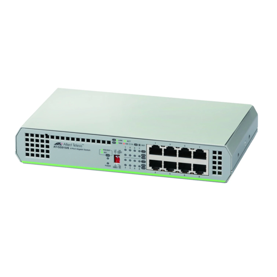
GS910 Series Gigabit Ehternet Unmanaged Switch Installation and User’s Guide AT-GS910/8 The AT-GS910/8 switch has eight 10/100/1000Base-TX twisted pair ports on the front panel as shown in Figure 5. Switch Figure 5. AT-GS910/8 Front Panel The AT-GS910/8 switch has an internal power supply with a single AC power supply socket on the rear panel as shown in Figure 6. -
Page 15: At-Gs910/16 Switch
Chapter 1: Product Description The AT-GS910/8E switch has an external power supply with a single DC power supply socket on the rear panel as shown in Figure 8. Figure 8. AT-GS910/8E Rear Panel Note The AT-GS910/8E power receptacle has a twist-and-lock barrel which is locked by turning the power cord clockwise one-quarter turn. -
Page 16: At-Gs910/24 Switch
GS910 Series Gigabit Ehternet Unmanaged Switch Installation and User’s Guide The AT-GS910/16 switch can be installed on a desktop, mounted on a wall, or mounted in a 19-inch equipment rack. To mount the switch on the wall or in an equipment rack, use the brackets that come with the switch. -
Page 17: Leds
Chapter 1: Product Description LEDs The LEDs on the front panel of the GS910 series switch display status information. LEDs for the AT-GS910/5 and AT-GS910/5 E Switches Table 2 describes the LEDs on the AT-GS910/5 and AT-GS910/5E switches. Table 2. LEDs for the AT-GS910/5 and AT-GS910/5E... -
Page 18: 10/100/1000 Base-Tx Twisted Pair Ports
GS910 Series Gigabit Ehternet Unmanaged Switch Installation and User’s Guide Table 3. LEDs for the AT-GS910/8, AT-GS910/8E, AT-GS910/16, and AT-GS910/24 Switches State Description Green The switch is powered ON and operating normally. The switch is not receiving power. LOOP Green The Loop Prevention is enabled. -
Page 19: Power Connector
Chapter 1: Product Description For example, if an end-node is capable of only 10 Mbps, the switch sets the port connected to the end-node to 10 Mbps. Duplex Mode Each twisted pair port on the switch can operate in either half- or full-duplex mode. -
Page 20: Key Features
GS910 Series Gigabit Ehternet Unmanaged Switch Installation and User’s Guide Key Features The GS910 series switches have the following key features: 10/100/1000 Mbps twisted pair ports with RJ-45 connectors IEEE802.3 compliant for 10Base-T IEEE802.3u compliant for 100Base-TX ... -
Page 21: Ethernet Switching Basics
The twisted pair ports on the GS910 series switch can operate in half- or full-duplex mode for 10/100 Mbps. They are IEEE 802.3u-compliant and use Auto-Negotiation to set the duplex mode setting for you automatically. - Page 22 GS910 Series Gigabit Ehternet Unmanaged Switch Installation and User’s Guide How a switch signals an end-node to stop transmitting data differs depending on the duplex mode of the end-node and switch port. A twisted pair port operating in half-duplex mode stops an end-node from transmitting data by forcing a collision.
-
Page 23: Loop Prevention
The LED of the blocked port starts blinking. In a topology with multiple GS910 series switches, these switches elect a root switch when Loop Prevention is enabled on all the switches. Initially, these switches are all root switches to send Loop Prevention frames, compare their MAC address, and elect a switch with the largest MAC address as a root switch. -
Page 24: Examples With Loop Prevention And Regular Switches
GS910 Series Gigabit Ehternet Unmanaged Switch Installation and User’s Guide Figure 13. Multiple AT-GS910 Switches for Loop Prevention Examples with In examples shown in Figure 14 on page 25, the AT-GS910 switch and a regular switch form links. When Loop Prevention is enabled, the Loop Prevention AT-GS910 switch sends Loop Prevention frames. -
Page 25: Examples Within A Loop Prevention Switch
Figure 15. AT-GS910 and Regular Switches for Loop Prevention - Case 3 Examples within In examples shown in Figure 16, the ports of the AT-GS910 switch connected. When Loop Prevention is enabled, the GS910 series switch a Loop blocks the port with the higher port number than the link partner port. -
Page 26: Guidelines For Loop Prevention
GS910 Series Gigabit Ehternet Unmanaged Switch Installation and User’s Guide Guidelines for Here are guidelines for using the Loop Prevention function: Loop Prevention The switch must have a unique MAC address. In a topology with multiple switches with Loop Prevention enabled, ... -
Page 27: Energy Efficiency Ethernet (Eee)
Chapter 1: Product Description Energy Efficiency Ethernet (EEE) The GS910 Series switches support IEEE 802.3az Energy Efficiency Ethernet (EEE) when the twisted pair ports are operating at a speed of 100Mbps or 1000Mbps. When EEE is enabled on the switch, the power consumption to keep links at a these speeds is reduced during periods of low data activity. - Page 28 GS910 Series Gigabit Ehternet Unmanaged Switch Installation and User’s Guide...
-
Page 29: Chapter 2: Installation
Chapter 2 Installation This chapter contains the following sections: “Reviewing Safety Precautions” on page 30 “Selecting a Site for the Switch” on page 32 “Planning the Installation” on page 33 “Unpacking the Switch” on page 34 “Installing the Switch on a Table or Desktop”... -
Page 30: Reviewing Safety Precautions
GS910 Series Gigabit Ehternet Unmanaged Switch Installation and User’s Guide Reviewing Safety Precautions Review the following safety precautions before you begin to install the switch. Note Important: The indicates that translations of the safety statement are available in the PDF document Translated Safety Statements posted on the Allied Telesis website at alliedtelesis.com/support. - Page 31 Chapter 2: Installation Note All Countries: Install product in accordance with local and National Electrical Codes. Note The power input must be provided from SELV source only, per IEC 60950. Do not connect to a centralized DC battery bank. ...
-
Page 32: Selecting A Site For The Switch
GS910 Series Gigabit Ehternet Unmanaged Switch Installation and User’s Guide Selecting a Site for the Switch Observe the following requirements when choosing a site for the GS910 series switch: If you plan to install the switch on a table, make sure that the table ... -
Page 33: Planning The Installation
Chapter 2: Installation Planning the Installation Table 5 contains the cabling specifications for the twisted pair ports. Table 5. Twisted Pair Cabling and Distances Maximum Speed Type of Cable Operating Distance 10 Mbps Category 3 or better unshielded 100 m (328 ft) twisted pair cable 100 Mbps Category 5 or unshielded twisted... -
Page 34: Unpacking The Switch
GS910 Series Gigabit Ehternet Unmanaged Switch Installation and User’s Guide Unpacking the Switch To unpack the GS910 series switch, perform the following procedure: 1. Remove all components from the shipping package. Note Store the packaging material in a safe location. You must use the original shipping material if you need to return the unit to Allied Telesis. - Page 35 Extension Four M3x6mm screws for attaching the brackets to the switch Two M4x6mm screws for attaching the right side bracket and extension 5. If any item is missing or damaged, contact your Allied Telesis sales representative for assistance.
-
Page 36: Installing The Switch On A Table Or Desktop
GS910 Series Gigabit Ehternet Unmanaged Switch Installation and User’s Guide Installing the Switch on a Table or Desktop To install the switch on a table or desktop, perform the following procedure: 1. Remove all the items from the packaging. 2. Store the packaging material in a safe place. -
Page 37: Installing The Switch On A Wall
Chapter 2: Installation Installing the Switch on a Wall The AT-GS910/5, AT-GS910/8, AT-GS910/8E, AT-GS910/16, and AT-GS910/24 switches can be mounted on a wall. Guidelines for Before planning to install the switch on a wall, review the following guidelines: Installing the Switch on a Wall To install the AT-GS910/16 or AT-GS910/24 switch, use the ... - Page 38 GS910 Series Gigabit Ehternet Unmanaged Switch Installation and User’s Guide Note To install the AT-GS910/24 switch on the wall, you must install the switch with the rear panel facing to the left in order for the switch to have proper air flow.
-
Page 39: What To Prepare For Installation With Brackets
Chapter 2: Installation What to Prepare You need the following items to install the switch on a wall: for Installation A switch with Brackets One pair of brackets (For more information, see “Wall and Rack Mount Brackets” on page 16.) Four screws to attach the brackets to a wall ... - Page 40 GS910 Series Gigabit Ehternet Unmanaged Switch Installation and User’s Guide 4. Have another person hold the switch with the brackets at the wall location where the switch is to be installed, while you use a pencil to mark the wall with the locations of the four holes in the brackets. See Figure 19 as an example.
-
Page 41: Installing The At-Gs910/24 Switch On A Wall
Chapter 2: Installation 7. Position the switch on the wall and drive screws through the holes to attach the brackets on the wall. See Figure 20. Figure 20. Driving the Screws through the Holes 8. Make sure that the two brackets are installed securely. 9. - Page 42 GS910 Series Gigabit Ehternet Unmanaged Switch Installation and User’s Guide 4. Orient the brackets against the sides of the switch and secure them to the switch with the four screws as shown in Figure 21. Figure 21. Attaching the Brackets to the AT-GS910/24 Switch 5.
- Page 43 Chapter 2: Installation 8. Position the switch on the wall and drive screws through the holes to attach the brackets on the wall. See Figure 23. Figure 23. Driving the Screws through the Holes 9. Make sure that the two brackets are installed securely. 10.
-
Page 44: Installing The Switch In An Equipment Rack
GS910 Series Gigabit Ehternet Unmanaged Switch Installation and User’s Guide Installing the Switch in an Equipment Rack The AT-GS910/8, AT-GS910/8E, AT-GS910/16 and AT-GS910/24 switches can be mounted on a 19-inch equipment rack. Guidelines for Before planning to install the switch on an equipment rack, review the... - Page 45 Chapter 2: Installation 2. Attach the extension to the bracket with the M4x6mm screws using a Phillips-head screw driver as shown in See Figure 24. Figure 24. Attaching the Extension to the Bracket 3. Turn the switch upside down and place it on a table. 4.
-
Page 46: Installing The At-Gs910/24 Switch In A Rack
GS910 Series Gigabit Ehternet Unmanaged Switch Installation and User’s Guide Figure 26. Attaching the Switch to an Equipment Rack 8. Proceed to “Cabling the Switch” on page 48. Installing the To install the AT-GS910/24 switch in an equipment rack with the brackets... - Page 47 Chapter 2: Installation 3. Attach the brackets to the switch with the M3x6mm screws using a Phillips-head screwdriver. See Figure 28. Figure 28. Attaching the Brackets to the Switch 4. Mount the switch in a standard 19-inch equipment rack with four equipment rack screws as shown in Figure 29.
-
Page 48: Cabling The Switch
GS910 Series Gigabit Ehternet Unmanaged Switch Installation and User’s Guide Cabling the Switch After installing the switch on the desktop, connect twisted pair cables to the ports on the GS910 series switch. When connecting a twisted pair cable to a port, observe the following guidelines: An RJ-45 connector should fit snugly into the port on the switch. -
Page 49: Powering On The Switch
Chapter 2: Installation Powering On the Switch To power on the switch, perform the following procedure: 1. Plug the power cord into the power connector on the back of the switch. 2. If your switch is the AT-GS910/5E or AT-GS910/8E switch with a DC power supply socket, turn the power cord clockwise one-quarter to lock, as shown in Figure 30. - Page 50 GS910 Series Gigabit Ehternet Unmanaged Switch Installation and User’s Guide...
-
Page 51: Chapter 3: Installation Using The At-Brkt-J23 Wall Mount Kit
Chapter 3 Installation Using the AT-BRKT-J23 Wall Mount Kit This chapter explains the procedures how to install a switch on a wall using the AT-BRKT-J23 wall mount kit. It contains the following sections: “Reviewing Safety Precautions” on page 52 “Unpacking the AT-BRKT-J23 Wall Mount Kit”... -
Page 52: Reviewing Safety Precautions
GS910 Series Gigabit Ehternet Switch Installation and User’s Guide Reviewing Safety Precautions Before you begin to install the switch using the AT-BRKT-J23 wall mount kit, review “Reviewing Safety Precautions” on page 30. -
Page 53: Unpacking The At-Brkt-J23 Wall Mount Kit
2. Verify that One pair of brackets is included in your wall mount package listed in Table 9. Table 9. Components in the AT-BRKT-J23 Wall Mount Kit Components One pair of brackets 3. If any item is missing or damaged, contact your Allied Telesis sales representative for assistance. -
Page 54: Installing A Switch Using The At-Brkt-J23 Wall Mount Kit
GS910 Series Gigabit Ehternet Switch Installation and User’s Guide Installing a Switch Using the AT-BRKT-J23 Wall Mount Kit This section shows you steps to install a switch on a wall using the AT-BRKT-J23 kit. What to Prepare Before installing a switch on a wall, make sure that the following items are ready. - Page 55 Chapter 3: Installation Using the AT-BRKT-J23 Wall Mount Kit 3. Pre-drill the marked locations on the wall at the locations marked in Step 2. 4. Install the four plastic anchors into the wall in the holes drilled in Step 5. Position brackets on the wall and drive screws through the holes to attach the brackets on the wall.
- Page 56 GS910 Series Gigabit Ehternet Switch Installation and User’s Guide 7. Slide the switch into the brackets on the wall as shown in Figure 33. Figure 33. Placing the Switch into the Brackets 8. Proceed to “Cabling the Switch” on page 48.
-
Page 57: Chapter 4: Installation Using The At-Rkmt-J08 Rack Mount Kit
Chapter 4 Installation Using the AT-RKMT-J08 Rack Mount Kit This chapter explains the procedures how to install a switch in a 19-inch equipment rack using the AT-RKMT-J08 rack mount kit. It contains the following sections: “Reviewing Safety Precautions” on page 58 ... -
Page 58: Reviewing Safety Precautions
GS910 Series Gigabit Ehternet Switch Installation and User’s Guide Reviewing Safety Precautions Before you begin to install the switch using the AT-RKMT-J08 rack mount kit, review “Reviewing Safety Precautions” on page 30. -
Page 59: Unpacking The At-Rkmt-J08 Rack Mount Kit
Chapter 4: Installation Using the AT-RKMT-J08 Rack Mount Kit Unpacking the AT-RKMT-J08 Rack Mount Kit To unpack the AT-RKMT-J08 rack mount kit, perform the following procedure: 1. Remove all components from the shipping package. Note Store the packaging material in a safe location. You must use the original shipping material if you need to return the unit to Allied Telesis. - Page 60 GS910 Series Gigabit Ehternet Switch Installation and User’s Guide Table 10. Components in the AT-RKMT-J08 Rack Mount Kit (Continued) Components Eight M4x6mm screws Ten Tie-wrap 3. If any item is missing or damaged, contact your Allied Telesis sales representative for assistance.
-
Page 61: Installing A Switch Using The At-Rkmt-J08 Rack Mount Kit
Chapter 4: Installation Using the AT-RKMT-J08 Rack Mount Kit Installing a Switch Using the AT-RKMT-J08 Rack Mount Kit This section shows you steps to install a switch in an equipment rack using the AT-RKMT-J08 kit. What to Prepare Before installing a switch to an equipment rack, make sure that the following items are ready. - Page 62 GS910 Series Gigabit Ehternet Switch Installation and User’s Guide 4. Attach the cable bracket to the unit that you assembled in Step 3 with M4x6mm screws using a Phillip-head screw driver as shown in Figure 36. Figure 36. Attaching Cable Tray to Plates 5.
- Page 63 Chapter 4: Installation Using the AT-RKMT-J08 Rack Mount Kit Figure 38. Attaching the Switch to Equipment Rack 8. Attach the power cord to the back panel of the switch. 9. Use a tie-warp to secure the power cord, as shown in Figure 39. Figure 39.
- Page 64 GS910 Series Gigabit Ehternet Switch Installation and User’s Guide...
-
Page 65: Chapter 5: Troubleshooting
If you are still unable to resolve the problem after following the instructions in this chapter, contact Allied Telesis Technical Support for assistance. Refer to “Contacting Allied Telesis” on page 9. Check the POWER LED on the front of the switch. If the LED is OFF,... - Page 66 GS910 Series Gigabit Ehternet Unmanaged Switch Installation and User’s Guide...
-
Page 67: Appendix A: Technical Specifications
Appendix A Technical Specifications This appendix contains the following sections: “Physical Specifications” “Environmental Specifications” “Safety and Electromagnetic Emissions Certifications” on page 68 “Power Specifications” on page 68 “RJ-45 Twisted Pair Port Connectors” on page 69 Physical Specifications Weight: AT-GS910/5... -
Page 68: Safety And Electromagnetic Emissions Certifications
GS910 Series Gigabit Ehternet Unmanaged Switch Installation and User’s Guide Safety and Electromagnetic Emissions Certifications FCC Class A, CISPR 22 Class A, CISPR 32 Class A, EN55022 Class A, EN55032 Class A, RCM, VCCI, ICES-003 Class A Immunity EN55024, EN61000-3-2, EN61000-3-3... -
Page 69: Twisted Pair Port Connectors
Appendix A: Technical Specifications RJ-45 Twisted Pair Port Connectors This section lists the connectors and connector pinouts for the AT-GS910 series switch and its components. Figure 40 illustrates the pin layout to an RJ-45 connector and port. Figure 40. RJ-45 Connector and Port Pin Layout Table 11 lists the RJ-45 pin signals when a twisted pair port is operating in the MDI configuration. - Page 70 GS910 Series Gigabit Ehternet Unmanaged Switch Installation and User’s Guide...
Need help?
Do you have a question about the GS910 Series and is the answer not in the manual?
Questions and answers