
Subscribe to Our Youtube Channel
Related Manuals for Allied Telesis CentreCOM GS970M Series


Summary of Contents for Allied Telesis CentreCOM GS970M Series
- Page 1 CentreCOM GS970M Series ® Gigabit Ethernet Switches AlliedWare Plus™ GS970M/10 GS970M/10PS GS970M/18 GS970M/18PS GS970M/28 GS970M/28PS Quick Installation Guide *613-003051 Rev A* 613-003051 Rev. A...
-
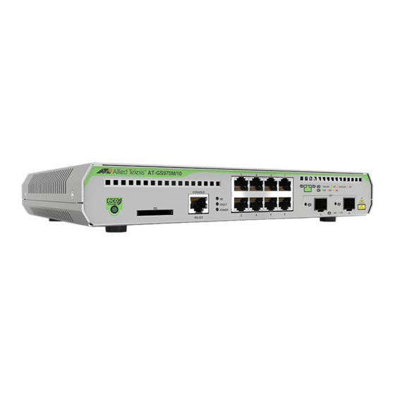
Page 2: Front Panels
This guide contains a short version of the installation instructions for the GS970M Series of Gigabit Ethernet Switches. For more instructions, refer to the GS970M Series of Gigabit Ethernet Switches Installation Guide on the Allied Telesis web site at www.alliedtelesis.com/us/en/services-support. This guide contains the following sections: “Front Panels”... - Page 3 Ports for 100Mbps and1Gbps SFP transceivers Here are the 10/100/1000Mbps Ethernet copper ports on the switches. 10/100/1000Mbps 10/100/1000Mbps Switch Ports Ports with PoE+ GS970M/10 Ports 1 to 8 GS970M/10PS Ports 1 to 8 GS970M/18 Ports 1 to 16 CentreCOM GS970M Series Quick Installation Guide...
-
Page 4: Poe+ Power Budgets
PoE+ switches can supply to powered devices on the Ethernet copper ports. The switches support IEEE 802.3at Classes 0 to 4 (maximum 30.0W at the ports). Switch PoE+ Budget GS970M/10PS 124 watts GS970M/18PS 247 watts GS970M/28PS 370 watts CentreCOM GS970M Series Quick Installation Guide... -
Page 5: Beginning The Installation
Note: The symbol indicates that a translation of the safety statement is available in the PDF document “Translated Safety Statements” on the Allied Telesis website at www.alliedtelesis.com/us/en/documents/translated-safety- statements. Warning: Class 1 Laser product. L1 Warning: Do not stare into the laser beam. L2 Warning: Power cord is used as a disconnection device. -
Page 6: Installation Options
Unpacking the Switch The switches come with these items: One 2m (6.6 ft) local management cable with RJ-45 (8P8C) and DB-9 (D-sub 9-pin) connectors One AC power cord One AC power cord retaining clip CentreCOM GS970M Series Quick Installation Guide... - Page 7 The following brackets for the GS970M Series are sold separately. RKMT-J05 bracket kit for installing the GS970M/10 Switch in an equipment rack. RKMT-J14 bracket kit for installing the GS970M/10PS Switch in an equipment rack. CentreCOM GS970M Series Quick Installation Guide...
- Page 8 Devices in a rack should be installed starting at the bottom of the rack, with the heavier devices near the bottom. Before installing the switch on a table, verify that the table is level and stable. CentreCOM GS970M Series Quick Installation Guide...
-
Page 9: Installing The Switch
To install the switch on a desk or table, perform the following procedure: 1. Verify that the table is secure and level. Verify that the location has adequate ventilation. 2. Place the switch at the selected location. 3. Go to “Ports” on page 13. CentreCOM GS970M Series Quick Installation Guide... - Page 10 M4x8mm screws included with the brackets. The figure shows the GS970M/28PS Switch. 3. Have another person hold the switch in the equipment rack while you secure it using four standard equipment rack screws (not provided). CentreCOM GS970M Series Quick Installation Guide...
- Page 11 E105 Note: You can install the switch on a wall with the front panel facing up, left, or right. Do not install it with the front panel facing down. CentreCOM GS970M Series Quick Installation Guide...
- Page 12 3. Have another person hold the switch on the wall at the selected location for the device while you use a pencil or pen to mark the wall with the locations of the four screw holes in the four brackets (one screw per bracket). CentreCOM GS970M Series Quick Installation Guide...
- Page 13 The ports must be set to Auto-Negotiation, the default setting, to operate at 1000Mbps. The ports support half- and full-duplex at 10Mbps or 100Mbps. The ports support only full-duplex at 1000Mbps. CentreCOM GS970M Series Quick Installation Guide...
-
Page 14: Installing Sfp Transceivers
You can install SFP transceivers while the switch is powered on. For a list of supported transceivers, refer to the product’s data sheet on the Allied Telesis web site at www.alliedtelesis.com. The operational specifications and fiber optic cable requirements are included with the transceivers. -
Page 15: Powering On The Switch
1. Install the power cord retaining clip on the AC power connector on the rear panel of the switch, and raise the clip. 2. Connect the power cord to the connector and lower the retaining clip to secure the power cord. CentreCOM GS970M Series Quick Installation Guide... -
Page 16: Ethernet Copper Port Leds
- The port has not established a link with another network device. - The LEDs are turned off. To turn on the LEDs, use the eco-friendly button. Duplex Mode LEDs - Non-PoE+ Switches Solid Green The port is operating in full-duplex mode. CentreCOM GS970M Series Quick Installation Guide... - Page 17 - The LEDs are turned off. To turn on the LEDs, use the eco-friendly button. SFP Port LEDs The SFP port LEDs are described here. LED for Top LED for Bottom SPF Port SPF Port CentreCOM GS970M Series Quick Installation Guide...
-
Page 18: System Leds
The SD slot is empty or the LEDs are off. Fault Flashing red The switch’s fan is failing or has stopped. once Flashing red six The switch is overheating and might shut times down. The switch is operating normally. CentreCOM GS970M Series Quick Installation Guide... -
Page 19: Starting A Local Management Session
Allied Telesis offers the VT-Kit3 management cable. It has a USB-A male connector that connects to a USB port on your workstation. The cable requires a software driver from Allied Telesis. The VT-Kit3 management cable is sold separately. To start a local management session, perform this procedure: 1. -
Page 20: Troubleshooting
Try the following: Verify that the fiber optic cable is securely connected to the port on the transceiver and to the port on the remote network device. CentreCOM GS970M Series Quick Installation Guide... - Page 21 Allied Telesis, Inc. reserves the right to make changes in specifications and other information contained in this document without prior written notice. The information provided herein is subject to change without notice. In no event shall Allied Telesis, Inc. be liable for any incidental, special, indirect, or consequential damages whatsoever, including but not limited to lost profits, arising out of or related to this manual or the information contained herein, even if Allied Telesis, Inc.
Need help?
Do you have a question about the CentreCOM GS970M Series and is the answer not in the manual?
Questions and answers