Allied Telesis GS950 PS V2 Series Installation Manual
Gigabit ethernet poe+ switches
Hide thumbs
Also See for GS950 PS V2 Series:
- Product information (2 pages) ,
- Product information (3 pages)

Related Manuals for Allied Telesis GS950 PS V2 Series


Summary of Contents for Allied Telesis GS950 PS V2 Series
- Page 1 GS950 PS V2 Series Gigabit Ethernet PoE+ Switches GS950/10PS V2 GS950/18PS V2 GS950/28PS V2 GS950/52PS V2 Installation Guide 613-002861 Rev. A...
- Page 2 Allied Telesis, Inc. has been advised of, known, or should have known, the...
- Page 3 Electrical Safety and Emissions Standards This product meets the following standards. U.S. Federal Communications Commission Radiated Energy Note: This equipment has been tested and found to comply with the limits for a Class A digital device pursuant to Part 15 of FCC Rules.
- Page 4 . Safety Certificates (Continued) Safety UL 62368-1 EN 62368-1 (TUV), CE IEC 60950-1 + IEC 62368-1 AEL Class I, US FDA/CDRH EN(IEC) 60825-1 EN(IEC) 60825-2 EN(IEC) 60950-1 CAN/CSA-C22.2 No 62368-1 Electromagnetic Certificates Electromagnetic Interference (EMI) FCC Part 15 Subpart B Class A EN 55032 Class A CISPR 32 VCCI Class A...
- Page 5 Translated Safety Statements Important: Safety statements that have the symbol are translated into multiple languages in the Translated Safety Statements document at www.alliedtelesis.com/library. Remarque: Les consignes de sécurité portant le symbole sont traduites dans plusieurs langues dans le document Translated Safety Statements, disponible à l'adresse www.alliedtelesis.com/ library.
-
Page 7: Table Of Contents
Contents Preface ....................................13 Document Conventions ...............................14 Contacting Allied Telesis ..............................15 Chapter 1: Overview ................................ 17 Front and Back Panels ................................18 Features ....................................21 Copper Ports ................................21 Power Over Ethernet Plus ............................21 SFP Slots ..................................21 System LEDs................................22 Port LEDs ..................................22 Installation Options ...............................22 Power Conservation ..............................22... - Page 8 Contents Plywood Base for a Wall with Wooden Studs ........................61 Tools and Material ................................63 Installing the Plywood Base ..............................64 Installing the Switch on the Plywood Base ......................... 65 Installing the Switch on a Concrete Wall..........................68 Installing the GS950/52PS V2 Switch on a Wall......................... 71 Chapter 6: Cabling the Networking Ports ........................
- Page 9 Figures Figure 1: Front Panel of the GS950/10PS V2 Switch ......................18 Figure 2: Front Panel of the GS950/18PS V2 Switch ......................18 Figure 3: Front Panel of the GS950/28PS V2 Switch ......................19 Figure 4: Front Panel of the GS950/52PS V2 Switch ......................19 Figure 5: Back Panel of the GS950/10PS V2 Switch ......................19 Figure 6: Back Panel of the GS950/18PS V2 and GS950/28PS V2 Switches ..............20 Figure 7: Back Panel of the GS950/52PS V2 Switch ......................20...
- Page 10 Figures Figure 50: Dimensions of the GS950/10PS V2 Switch ......................96 Figure 51: Dimensions of the GS950/18PS V2 and GS950/28PS V2 Switches..............97 Figure 52: Dimensions of the GS950/52PS V2 Switch ......................98 Figure 53: Locations of the Bracket Holes on the GS950/10PS V2 Switch ................98 Figure 54: Locations of the Bracket Holes on the GS950/18PS V2 and GS950/28PS V2 Switches........99 Figure 55: Locations of the Bracket Holes on the GS950/52PS V2 Switch ................99 Figure 56: Pin Layout (Front View) of Copper Ports ......................106...
- Page 11 Tables Table 1: Safety Certificates ..............................3 Table 2: Electromagnetic Certificates ............................4 Table 3: Features of the Copper Ports ..........................24 Table 4: PoE Maximum Power Budgets and Ports ......................26 Table 5: IEEE Powered Device Classes ..........................27 Table 6: SYSTEM LED ................................30 Table 7: POWER LED .................................31 Table 8: PoE MAX LED ...............................31 Table 9: Link/Activity and PoE LEDs for the Copper Ports ....................33...
- Page 12 Tables...
-
Page 13: Preface
Preface This guide contains the hardware installation instructions for the GS950 PS V2 Series of Gigabit Ethernet switches, with Power over Ethernet Plus (PoE+). The preface contains the following sections: “Document Conventions” on page 14 “Contacting Allied Telesis” on page 15... -
Page 14: Document Conventions
Preface Document Conventions This document uses the following conventions: Note Notes provide additional information. Caution Cautions inform you that performing or omitting a specific action may result in equipment damage or loss of data. Warning Warnings inform you that performing or omitting a specific action may result in bodily injury. -
Page 15: Contacting Allied Telesis
Warranty - View a list of products to see if Allied Telesis warranty applies to the product you purchased and register your warranty. Allied Telesis Helpdesk - Contact a support representative. - Page 16 Preface...
- Page 17 Chapter 1 Overview This chapter describes the hardware features of the GS950 PS V2 Series of Gigabit Ethernet PoE+ switches in the following sections: “Front and Back Panels” on page 18 “Features” on page 21 “Management Software” on page 23 ...
-
Page 18: Chapter 1: Overview
Chapter 1: Overview Front and Back Panels Figure 1 illustrates the front panel of the GS950/10PS V2 Switch. Port LEDs Eight 10/100/1000Mbps 100/1000Mbps Copper Ports with SFP Ports PoE MAX and PoE+ POWER LEDs eco-Friendly Button Figure 1. Front Panel of the GS950/10PS V2 Switch Figure 2 illustrates the front panel of the GS950/18PS V2 Switch. -
Page 19: Figure 3: Front Panel Of The Gs950/28Ps V2 Switch
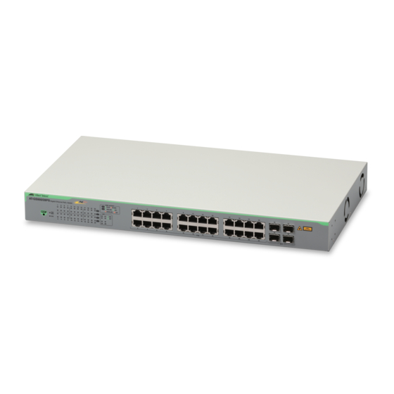
GS950 PS V2 Series of Gigabit Ethernet PoE+ Switches Installation Guide Figure 3 illustrates the front panel of the GS950/28PS V2 Switch. Port LEDs Twenty Four Four 100/1000Mbps 10/100/1000Mbps Copper Ports with SFP Ports PoE MAX and PoE+ SYSTEM LEDs... -
Page 20: Figure 6: Back Panel Of The Gs950/18Ps V2 And Gs950/28Ps V2 Switches
Chapter 1: Overview Figure 6 illustrates the back panel of the GS950/18PS V2 and GS950/ 28PS V2 Switches. 100-240VAC~, 3.5A 50/60Hz AC Input Figure 6. Back Panel of the GS950/18PS V2 and GS950/28PS V2 Switches Figure 7 illustrates the back panel of the GS950/52PS V2 Switch. 100-240VAC~, 10A 50/60Hz AC Input Figure 7. -
Page 21: Features
GS950 PS V2 Series of Gigabit Ethernet PoE+ Switches Installation Guide Features Here are the hardware features of the switches. Copper Ports Here are the basic features of the copper ports: 10/100/1000Mbps 10Base-T, 100Base-TX and 1000Base-T compliant ... -
Page 22: System Leds
1000Mbps 1000Base-T copper transceiver Note Transceivers are purchased separately. For a list of supported transceivers, refer to the product’s data sheet on the Allied Telesis web site. System LEDs The port LEDs are briefly described here: ... -
Page 23: Management Software
GS950 PS V2 Series of Gigabit Ethernet PoE+ Switches Installation Guide Management Software The switch comes with the management software pre-installed. The software has a web-browser interface for in-band, over-the-network management from your management workstations and a web browser. The web-based interface lets you manage all of the functions and features of the switch as well as view status information and traffic statistics. -
Page 24: Copper Ports
Chapter 1: Overview Copper Ports Table 1 lists the features of the copper ports. Table 1. Features of the Copper Ports Feature Description Speeds Port speeds are listed here: - 10Mbps (IEEE802.3 10Base-T) - 100Mbps (IEEE802.3u 100Base-TX) - 1Gbps (IEEE802.3ab 10Base-T) Speeds are set manually or with Auto- Negotiation. - Page 25 GS950 PS V2 Series of Gigabit Ethernet PoE+ Switches Installation Guide Table 1. Features of the Copper Ports (Continued) Feature Description Additional Additional features are listed here: - 8-pin RJ-45 connectors - Backpressure flow control supported at half- duplex mode - Non-blocking, wire speed supported at all speeds.
-
Page 26: Power Over Ethernet (Poe)
Chapter 1: Overview Power over Ethernet (PoE) The GS950 PS V2 Switches feature PoE on the copper ports. This feature enables the switch to supply power to network devices over the same cables that carry the network traffic. The value of PoE is that it can make installing a network easier. -
Page 27: Poe Standards
GS950 PS V2 Series of Gigabit Ethernet PoE+ Switches Installation Guide PoE Standards The GS950 PS V2 Switches support these PoE standards: PoE (IEEE 802.3af): This standard provides up to 15.4 watts at the switch port to support powered devices that require up to 12.95 watts. - Page 28 Chapter 1: Overview Critical ports are receiving power. Ports that are connected to your most critical powered devices should be assigned to this level. If there is not enough power to support all the ports set to the Critical priority level, power is allocated to ports based on port number, in ascending order.
-
Page 29: Sfp Ports
GS950 PS V2 Series of Gigabit Ethernet PoE+ Switches Installation Guide SFP Ports The SFP ports support the following types of transceivers: SFP 100Mbps (100Base-FX) fiber optic transceivers SFP 1000Mbps (1000Base-SX/LX) fiber optic transceivers Single-port bidirectional SFP 1000Mbps (1000Base-SX/LX) fiber optic transceivers ... -
Page 30: Leds
Chapter 1: Overview LEDs The switch LEDs are described in the following sections: “SYSTEM LED” next “POWER LED” on page 31 “PoE MAX LED” on page 31 “Link/Activity and PoE LEDs” on page 31 “SFP LEDs” on page 34 Note If all the port LEDs are off, the switch may be operating in the low power mode. -
Page 31: Power Led
GS950 PS V2 Series of Gigabit Ethernet PoE+ Switches Installation Guide POWER LED The GS950/10PS V2 Switch has a POWER LED on the left side of the faceplate. Refer to Figure 9. Figure 9. POWER LED Table 5 defines the LED states. -
Page 32: Figure 10: Link/Activity And Poe Leds For The Copper Ports On The Gs950/28Ps V2 Switch
Chapter 1: Overview Figure 10. Link/Activity and PoE LEDS for the Copper Ports on the GS950/28PS V2 Switch Copper ports 1 to 24 on the GS950/52PS V2 Switch have link/activity and PoE LEDs directly above and below the ports. Refer to the Figure 11. Figure 11. -
Page 33: Figure 12: Link/Activity Leds For Copper Ports 25 To 48 On The Gs950/52Ps V2 Switch
GS950 PS V2 Series of Gigabit Ethernet PoE+ Switches Installation Guide Unused. Unused. Figure 12. Link/Activity LEDS for Copper Ports 25 to 48 on the GS950/ 52PS V2 Switch Table 7 defines the states of the port LEDs. Table 7. Link/Activity and PoE LEDs for the Copper Ports... -
Page 34: Sfp Leds
Chapter 1: Overview Table 7. Link/Activity and PoE LEDs for the Copper Ports (Continued) State Description This state has the following possible causes: - The port is not connected to a network device. - The port is connected to a non-PoE device. -
Page 35: Figure 14: Leds For The Sfp Ports On The Gs950/52Ps V2 Switch
GS950 PS V2 Series of Gigabit Ethernet PoE+ Switches Installation Guide The LEDs for the four SFP ports on the GS950/52PS V2 Switch are located between the ports. Refer to Figure 14. Figure 14. LEDs for the SFP Ports on the GS950/52PS V2 Switch The states of the SFP port LEDs are defined in Table 8. -
Page 36: Eco-Friendly Button
Chapter 1: Overview eco-Friendly Button You can use the eco-Friendly button, shown in Figure 15, to perform the following functions: Toggling the eco-Friendly mode: Pressing the button for less than five seconds toggles the front panel LEDs on and off. You might turn off the LEDs to conserve electricity when you are not using them to monitor the switch. -
Page 37: Rebooting Or Restoring The Switch
GS950 PS V2 Series of Gigabit Ethernet PoE+ Switches Installation Guide Caution The switch temporarily stops forwarding network traffic when you reboot it or restore the default settings. Some network traffic may be lost. E113 Note You can disable both the reboot and factory default reset functions of the eco-Friendly button In the management software. -
Page 38: Power Supply And Fans
Chapter 1: Overview Power Supply and Fans The switches have one internal power supply with a single AC power supply socket on the back panel. You can power the switch on or off either by powering on or off the AC power source or by connecting or disconnecting the power cord. -
Page 39: Chapter 2: Beginning The Installation
Chapter 2 Beginning the Installation The chapter contains the following sections: “Reviewing Safety Precautions” on page 40 “Installation Options” on page 45 “Choosing a Site for the Switch” on page 46 “Unpacking the Switch” on page 47... -
Page 40: Reviewing Safety Precautions
Chapter 2: Beginning the Installation Reviewing Safety Precautions Please review the following safety precautions before beginning the installation procedure. Note Safety statements that have the symbol are translated into multiple languages in the Translated Safety Statements document at www.alliedtelesis.com/support. Warning Laser Radiation. - Page 41 GS950 PS V2 Series of Gigabit Ethernet PoE+ Switches Installation Guide Warning Power cord is used as a disconnection device. To de-energize equipment, disconnect the power cord. E3 Warning Class I Equipment. This equipment must be earthed. The power plug must be connected to a properly wired earth ground socket outlet.
- Page 42 Chapter 2: Beginning the Installation Caution Circuit Overloading: Consideration should be given to the connection of the equipment to the supply circuit and the effect that overloading of circuits might have on overcurrent protection and supply wiring. Appropriate consideration of equipment nameplate ratings should be used when addressing this concern.
- Page 43 GS950 PS V2 Series of Gigabit Ethernet PoE+ Switches Installation Guide Warning SFP transceivers can be damaged by static electricity. Be sure to observe all standard electrostatic discharge (ESD) precautions, such as wearing an anti-static wrist strap, to avoid damaging transceivers.
- Page 44 Chapter 2: Beginning the Installation Warning This product may have multiple AC power cords installed. To de- energize this equipment, disconnect all power cords from the device. E41 Caution An Energy Hazard exists inside this equipment. Do not insert hands or tools into open chassis slots or plugs.
-
Page 45: Installation Options
GS950 PS V2 Series of Gigabit Ethernet PoE+ Switches Installation Guide Installation Options Figure 17 illustrates the installation options. Desk or Table 19-inch Equipment Rack Wall Figure 17. Installation Options... -
Page 46: Choosing A Site For The Switch
Chapter 2: Beginning the Installation Choosing a Site for the Switch Observe these site requirements. If you are installing the device in an equipment rack, check that the rack is safely secured so that it will not tip over. Devices should be installed in the rack starting at the bottom, with the heavier devices near the bottom of the rack. -
Page 47: Unpacking The Switch
GS950 PS V2 Series of Gigabit Ethernet PoE+ Switches Installation Guide Unpacking the Switch Warning The device is heavy. Use both hands to lift it. You might injure yourself or damage the device if you drop it. E94 After unpacking the switch from the shipping box, visually inspect it for damage and verify the contents. -
Page 48: Figure 19: Equipment Rack/Wall Brackets
Chapter 2: Beginning the Installation Equipment rack/wall brackets for the GS950/10PS V2 Switch Equipment rack/wall brackets for the GS950/18PS V2 and GS950/28PS V2 Switches Equipment rack brackets for the GS950/52PS V2 Switch Figure 19. Equipment Rack/Wall Brackets Note Installing the GS950/52PS V2 Switch on a wall requires the optional BRKT-J22 brackets. -
Page 49: Chapter 3: Installing The Switch On A Table Or Desktop
Chapter 3 Installing the Switch on a Table or Desktop This chapter contains the instructions for installing the switch on a table or desktop. Warning Switches should not be stacked on a table or desktop. They could present a physical safety hazard if you need to move or replace switches. -
Page 50: Figure 20: Affixing The Bumper Feet
Chapter 3: Installing the Switch on a Table or Desktop Figure 20. Affixing the Bumper Feet 6. Turn the switch over and place it on a flat, secure desk or table, leaving ample space around it for ventilation. 7. Go to Chapter 6, “Cabling the Networking Ports” on page 75. -
Page 51: Chapter 4: Installing The Switch In An Equipment Rack
Chapter 4 Installing the Switch in an Equipment Rack This chapter contains instructions for installing the switch in a standard 19- inch equipment rack. The procedures are listed here: “Beginning the Installation” on page 52 “Installing the Switch” on page 53... -
Page 52: Beginning The Installation
Chapter 4: Installing the Switch in an Equipment Rack Beginning the Installation This chapter contains the procedure for installing the switch in a standard 19-inch equipment rack, with the brackets included with the unit. Required Items The following items are required to install the switch in an equipment rack: ... -
Page 53: Installing The Switch
GS950 PS V2 Series of Gigabit Ethernet PoE+ Switches Installation Guide Installing the Switch Please review the information and perform the procedures in Chapter 2, “Beginning the Installation” on page 39 before installing the switch. Caution The chassis may be heavy and awkward to lift. Allied Telesis recommends that you get assistance when mounting the chassis in an equipment rack. -
Page 54: Figure 22: Attaching The Equipment Rack Brackets
Chapter 4: Installing the Switch in an Equipment Rack Figure 22. Attaching the Equipment Rack Brackets 4. Have another person hold the switch in the equipment rack while you secure it using the four equipment rack screws provided with the switch. -
Page 55: Chapter 5: Installing The Switch On A Wall
Chapter 5 Installing the Switch on a Wall The procedures in this chapter are listed here: “Switch Orientations on a Wall” on page 56 “Installation Guidelines” on page 58 “Recommended Minimum Reserved Wall Area” on page 59 ... -
Page 56: Switch Orientations On A Wall
Chapter 5: Installing the Switch on a Wall Switch Orientations on a Wall You can install the switch on a wall with the front panel facing up or down. Figure 24 shows the correct wall installations. Figure 24. Wall Installations... -
Page 57: Figure 25: Unsupported Switch Orientations On A Wall
GS950 PS V2 Series of Gigabit Ethernet PoE+ Switches Installation Guide Do not install the switch on a wall with the front panel facing left or right. These orientations may reduce airflow though the device, which can cause it to overheat. Refer to Figure 25. -
Page 58: Installation Guidelines
Chapter 5: Installing the Switch on a Wall Installation Guidelines Here are the guidelines to installing the switch on a wall: You can install the switch on a wooden or concrete wall. If you are installing the switch on a wall with wooden studs with the standard brackets, you should use a plywood base to support the device. -
Page 59: Recommended Minimum Reserved Wall Area
GS950 PS V2 Series of Gigabit Ethernet PoE+ Switches Installation Guide Recommended Minimum Reserved Wall Area Figure 26 and Figure 27 on page 60 illustrate the recommended minimum reserved wall area around the switch, with the front panel facing up or down, respectively. -
Page 60: Figure 27: Recommended Minimum Reserved Wall Area With The Front Panel Facing Down
Chapter 5: Installing the Switch on a Wall 10.2 cm (4 in) 10.2 cm 10.2 cm (4 in) (4 in) Front Panel 15.2 cm (6 in) Figure 27. Recommended Minimum Reserved Wall Area with the Front Panel Facing Down... -
Page 61: Plywood Base For A Wall With Wooden Studs
GS950 PS V2 Series of Gigabit Ethernet PoE+ Switches Installation Guide Plywood Base for a Wall with Wooden Studs Allied Telesis recommends using a plywood base to install the switch on a wall that has wooden studs. Refer to Figure 28. -
Page 62: Figure 29: Steps To Installing The Switch With A Plywood Base
Chapter 5: Installing the Switch on a Wall You should install the plywood base to the wall and then install the switch on the base. Refer to Figure 29. Wall Studs Plywood Base Step 1: Install the plywood base on the Wall wall. -
Page 63: Tools And Material
GS950 PS V2 Series of Gigabit Ethernet PoE+ Switches Installation Guide Tools and Material Here are the required tools and material for installing the switch on a wooden wall with the standard brackets that come with the device: Two standard brackets ... -
Page 64: Installing The Plywood Base
Chapter 5: Installing the Switch on a Wall Installing the Plywood Base A plywood base is recommended when installing the switch on a wall that has wooden studs, with the standard brackets. Consult a qualified building contractor for installation instructions for the base. The installation guidelines are listed here: ... -
Page 65: Installing The Switch On The Plywood Base
GS950 PS V2 Series of Gigabit Ethernet PoE+ Switches Installation Guide Installing the Switch on the Plywood Base This procedure assumes that the plywood base for the switch is installed on the wall. Please review “Reviewing Safety Precautions” on page 40 and “Choosing a Site for the Switch”... -
Page 66: Figure 30: Installing The Brackets To The Switch For Wall Installation
Chapter 5: Installing the Switch on a Wall Figure 30. Installing the Brackets to the Switch for Wall Installation 3. After attaching the brackets to the side of the switch, have another person hold the switch on the plywood base on the wall while you secure it with the four provided screws. -
Page 67: Figure 31: Attaching The Switch To The Plywood Base
GS950 PS V2 Series of Gigabit Ethernet PoE+ Switches Installation Guide Figure 31. Attaching the Switch to the Plywood Base... -
Page 68: Installing The Switch On A Concrete Wall
Chapter 5: Installing the Switch on a Wall Installing the Switch on a Concrete Wall Allied Telesis recommends a minimum of two people for this procedure. Warning The device should be installed on a wall by a qualified building contractor. Serious injury to yourself or others or damage to the equipment may result if it is not properly fastened to the wall. -
Page 69: Figure 32: Marking The Locations Of The Bracket Holes On A Concrete Wall
GS950 PS V2 Series of Gigabit Ethernet PoE+ Switches Installation Guide Figure 32. Marking the Locations of the Bracket Holes on a Concrete Wall 4. Place the switch on a table or desk. 5. Use a drill and 1/4” carbide drill bit to pre-drill the four holes you marked in step 3. -
Page 70: Figure 33: Installing The Switch On A Concrete Wall
Chapter 5: Installing the Switch on a Wall Figure 33. Installing the Switch on a Concrete Wall 8. Go to Chapter 6, “Cabling the Networking Ports” on page 75. -
Page 71: Installing The Gs950/52Ps V2 Switch On A Wall
GS950 PS V2 Series of Gigabit Ethernet PoE+ Switches Installation Guide Installing the GS950/52PS V2 Switch on a Wall For wall installations of the GS950/52PS V2 Switch, Allied Telesis recommends the optional BRKT-J22 Brackets kit. The kit consists of four identical brackets, shown in Figure 34. -
Page 72: Figure 36: Marking The Screw Holes For The Brkt-J22 Brackets
Chapter 5: Installing the Switch on a Wall Note Wall anchors and screws are not provided with the brackets. The diameter of the bracket screw holes is 4mm. To install the GS950/52PS V2 Switch on a wall with the BRKT-J22 Brackets, perform the following procedure: 1. -
Page 73: Figure 37: Attaching The Bottom Brkt-J22 Brackets To The Wall
GS950 PS V2 Series of Gigabit Ethernet PoE+ Switches Installation Guide Flange Flange Figure 37. Attaching the Bottom BRKT-J22 Brackets to the Wall 7. Slide the bottom panel of the switch into the brackets. Refer to Figure 38. Figure 38. Sliding the Switch into the Bottom BRKT-J22 Brackets... -
Page 74: Figure 39: Attaching The Top Brkt-J22 Brackets To The Wall
Chapter 5: Installing the Switch on a Wall Warning Continue to hold the switch on the wall until after you complete the next step, which installs the top brackets. Otherwise, the switch may fall off the wall. 8. Attach the top brackets to the wall with appropriate screws. Refer to Figure 39. -
Page 75: Chapter 6: Cabling The Networking Ports
Chapter 6 Cabling the Networking Ports This chapter contains the following procedures: “Cabling the Copper Ports” on page 76 “Installing SFP Transceivers” on page 78... -
Page 76: Cabling The Copper Ports
Chapter 6: Cabling the Networking Ports Cabling the Copper Ports Here are the guidelines to cabling the 10/100/1000Mbps copper ports: The cable specifications are listed in Table 1 on page 24. The connectors on the cables should fit snugly into the ports, and the tabs should lock the connectors into place. - Page 77 GS950 PS V2 Series of Gigabit Ethernet PoE+ Switches Installation Guide uses MDI and the other MDI-X. For example, if a network device has a fixed wiring configuration of MDI, you should disable auto- MDI/MDI-X on the corresponding switch port and manually set it to MDI-X.
-
Page 78: Installing Sfp Transceivers
For a list of supported transceivers, refer to the product’s data sheet on the Allied Telesis web site at www.alliedtelesis.com. The operational specifications and fiber optic cable requirements are included with the transceivers. -
Page 79: Figure 40: Installing An Sfp Transceiver
GS950 PS V2 Series of Gigabit Ethernet PoE+ Switches Installation Guide Figure 40. Installing an SFP Transceiver Note If you are ready to attach the fiber optic cable to the transceiver, continue with the next step. Otherwise, repeat steps 1 to 3 to install another SFP transceiver in the switch. -
Page 80: Figure 42: Positioning The Sfp Handle In The Upright Position
Chapter 6: Cabling the Networking Ports 5. Verify the position of the handle on the SFP transceiver. If the transceiver is in a top slot, the handle should be in the upright position, as shown in Figure 42. If the transceiver is in a bottom slot, the handle should be in the down position. -
Page 81: Chapter 7: Powering On The Switch
Chapter 7 Powering On the Switch This chapter contains the following sections: “Powering On the Switch” on page 82 “Starting the First Management Session” on page 85... -
Page 82: Powering On The Switch
Chapter 7: Powering On the Switch Powering On the Switch This section contains the procedure for powering on the switch. Please refer to “Power Specifications” on page 118 for the power specifications before performing the procedure. Please review the following information before powering on the unit: ... -
Page 83: Figure 45: Raising The Retaining Clip
GS950 PS V2 Series of Gigabit Ethernet PoE+ Switches Installation Guide 2. Raise the retaining clip. Refer to Figure 45. Figure 45. Raising the Retaining Clip 3. Connect the power cord to the connector. Refer to Figure 46. Figure 46. Plugging in the AC Power Cord 4. -
Page 84: Figure 47: Lowering The Retaining Clip
Chapter 7: Powering On the Switch Figure 47. Lowering the Retaining Clip 5. Connect the other end of the power cord to an appropriate power source. Refer to Figure 48. Warning Power cord is used as a disconnection device. To de-energize equipment, disconnect the power cord. -
Page 85: Starting The First Management Session
GS950 PS V2 Series of Gigabit Ethernet PoE+ Switches Installation Guide Starting the First Management Session When you power on the GS950/28PS V2 Switch for the first time, it transmits DHCP queries for a DHCP server on all its ports. If a DHCP server responds, the unit uses the IP address the server assigns to it. -
Page 86: Starting The First Management Session With A Dhcp Server
Chapter 7: Powering On the Switch Starting the First This procedure explains how to start the first management session on the GS950/28PS V2 Switch when the LAN port is connected to a network that Management has a DHCP server. To start the management session, perform the Session with a following procedure: DHCP Server... -
Page 87: Starting The First Management Session Without A Dhcp Server
GS950 PS V2 Series of Gigabit Ethernet PoE+ Switches Installation Guide 3. Set the subnet mask on your computer to 255.255.255.0. 4. Power on the switch. 5. Start the web browser on your computer. 6. Enter the IP address 192.168.1.1 in the URL field of the browser. - Page 88 Chapter 7: Powering On the Switch...
-
Page 89: Chapter 8: Troubleshooting
“AC Power” on page 90 “LEDs” on page 91 “Copper Ports” on page 92 “SFP Ports” on page 93 “Power Over Ethernet” on page 94 Note For further assistance, please contact Allied Telesis Technical Support at www.alliedtelesis.com/support. -
Page 90: Ac Power
Chapter 8: Troubleshooting AC Power The switch is functioning intermittently or shut down and powered off. One possible cause is the unit may have overheated. Try the following: Verify that the location of the switch allows for adequate airflow. ... -
Page 91: Leds
GS950 PS V2 Series of Gigabit PoE+ Ethernet Switches Installation Guide LEDs The PWR LED on the front of the switch is off, indicating the unit is not receiving power. Try the following: Verify that the power cord is securely connected to the power source and the AC connector on the back panel of the switch. -
Page 92: Copper Ports
Chapter 8: Troubleshooting Copper Ports A copper port on the switch is connected to a network device, but its Link/ Activity LED is off. This indicates the port is not able to establish a link to a network device. Try the following: ... -
Page 93: Sfp Ports
GS950 PS V2 Series of Gigabit PoE+ Ethernet Switches Installation Guide SFP Ports The Link/Activity LED for an SFP transceiver is off, signaling that the fiber optic port on the transceiver has not established a link to a remote network device. -
Page 94: Power Over Ethernet
Chapter 8: Troubleshooting Power Over Ethernet A switch port is not supplying power to a PoE device. Try the following: Use the management software to determine whether the switch has already reached its maximum power budget of 185W and cannot support additional powered devices. -
Page 95: Appendix A: Technical Specifications
Appendix A Technical Specifications This appendix contains the following sections: ”Physical Specifications” on page 96 ”Environmental Specifications” on page 101 ”Power Specifications” on page 102 ”Certifications” on page 104 ”RJ-45 Copper Port Pinouts” on page 106... -
Page 96: Physical Specifications
Appendix A: Technical Specifications Physical Specifications Dimensions (H x W x D) Table 9 lists the dimensions of the switch. Table 9. Product Dimensions GS950/10PS V2 4.4 cm x 33.0 cm x 18.0 cm (1.7 in. x 13.0 in. x 7.1 in.) GS950/18PS V2 4.4 cm x 44.0 cm x 25.0 cm (1.7 in. -
Page 97: Figure 51: Dimensions Of The Gs950/18Ps V2 And Gs950/28Ps V2 Switches
GS950 PS V2 Series of Gigabit Ethernet PoE+ Switches Installation Guide The dimensions of the GS950/18PS V2 and GS950/28PS V2 Switches are shown in Figure 51. Width 44.0 cm (17.3 in.) Height 4.4 cm (1.7 in.) Depth 25 cm (9.8 in.) Figure 51. -
Page 98: Figure 52: Dimensions Of The Gs950/52Ps V2 Switch
Appendix A: Technical Specifications The dimensions of the GS950/52PS V2 Switch are shown in Figure 52. Width 44.0 cm (17.3 in.) Height 4.4 cm (1.7 in.) Depth 43.1 cm (17.0 in.) Figure 52. Dimensions of the GS950/52PS V2 Switch Locations of the bracket holes on the GS950/10PS V2 Switch are shown in Figure 53. -
Page 99: Figure 54: Locations Of The Bracket Holes On The Gs950/18Ps V2 And Gs950/28Ps V2 Switches
GS950 PS V2 Series of Gigabit Ethernet PoE+ Switches Installation Guide Locations of the bracket holes on the GS950/18PS V2 and GS950/28PS V2 Switches are shown in Figure 54. 0.00 mm (0.00 in.) 12 mm (0.47 in.) 32 mm (1.26 in.) Figure 54. - Page 100 Appendix A: Technical Specifications Weight Table 10 lists the weight of the switches. Table 10. Product Weights GS950/10PS V2 1.9 kg (4.2 lb.) GS950/18PS V2 3.7 kg (8.2 lb.) GS950/28PS V2 3.8 kg (8.4lb.) GS950/52PS V2 6.1 kg (13.4 lb.) Ventilation Table 11 lists the minimum ventilation requirements.
-
Page 101: Environmental Specifications
GS950 PS V2 Series of Gigabit Ethernet PoE+ Switches Installation Guide Environmental Specifications Table 12 lists the environmental specifications of the switch. Table 12. Environmental Specifications Operating Temperature: 0° C to 40° C (32° F to 104° F) GS950/10PS V2 Operating Temperature: 0°... -
Page 102: Power Specifications
Appendix A: Technical Specifications Power Specifications This section contains maximum power consumption and input voltage. Maximum Power Consumption Table 13 lists the maximum power consumption for the switch. Table 13. Maximum Power Consumptions GS950/10PS V2 97.7 watts GS950/18PS V2 239.7 watts GS950/28PS V2 247.4 watts GS950/52PS V2... - Page 103 GS950 PS V2 Series of Gigabit Ethernet PoE+ Switches Installation Guide Typical Power Savings in eco-friendly Mode Table 16 lists the typical power savings in eco-friendly mode. Table 16. Typical Power Savings in eco-friendly Mode GS950/10PS V2 0.4 watt GS950/18PS V2 0.6 watt...
-
Page 104: Certifications
Appendix A: Technical Specifications Certifications Table 18 lists the safety certificates. Table 18. Safety Certificates Euro Zone North America FCC/ICES/UL Australia/New Zealand Japan VCCI Russia Mexico India Brazil ANATEL Safety UL 62368-1 EN 62368-1 (TUV), CE IEC 60950-1 + IEC 62368-1 AEL Class I, US FDA/CDRH EN(IEC) 60825-1 EN(IEC) 60825-2... - Page 105 GS950 PS V2 Series of Gigabit Ethernet PoE+ Switches Installation Guide Table 19. Electromagnetic Certificates (Continued) RoHS EU RoHS Directove (2011/65/EU) (2015/863) China RoHS Additional JGPSSI/JIG Level A...
-
Page 106: Copper Port Pinouts
Appendix A: Technical Specifications RJ-45 Copper Port Pinouts Figure 56 illustrates the pin layout of the RJ-45 connectors. Figure 56. Pin Layout (Front View) of Copper Ports Table 20 lists the pin signals at 10/100Mbps. Table 20. Pin Signals on RJ-45 Copper Ports at 10/100Mbps MDI Signal MDI-X Signal Not used... - Page 107 GS950 PS V2 Series of Gigabit Ethernet PoE+ Switches Installation Guide Table 21. Pin Signals on Copper Ports at 1Gbps (Continued) TX and RX- TX and RX- TX and RX+ TX and RX-...
- Page 108 Appendix A: Technical Specifications...
Need help?
Do you have a question about the GS950 PS V2 Series and is the answer not in the manual?
Questions and answers