Xerox Phaser 7760 Service Manual
Color laser printer
Hide thumbs
Also See for Phaser 7760:
- User manual (158 pages) ,
- Advanced features manual (105 pages) ,
- Evaluator manual (20 pages)
Table of Contents
Advertisement
Quick Links
Advertisement
Chapters
Table of Contents

Related Manuals for Xerox Phaser 7760


Summary of Contents for Xerox Phaser 7760
- Page 1 Phaser ® 7760 Color Laser Printer Phaser 7760 ® Service Manual...
- Page 3 Xerox does not warrant or represent that such documentation is com- United States and/or other countries. plete, nor does Xerox represent or warrant that it will notify or provide to such customer any future changes to this documentation. Customer performed service of equipment, or modules, Novell®, NetWare®, NDPS®, NDS®, Novell Directory Services®, IPX™, and Novell Distrib-...
- Page 4 Revised January 2010 Phaser 7760 Color Laser Printer...
-
Page 5: Table Of Contents
Electrostatic Discharge (ESD) Precautions..............Generic Warnings with FIGS................... Symbology and Nomenclature ..................Regulatory Specifications....................xiii Phaser 7760 Printer Introduction and Overview ............. Phaser 7760 Printer Configurations ................Parts of the Printer ......................Phaser 7760 Control Panel Configuration............... xviii Image Processor Board and Rear Panel Host Interface .......... - Page 6 Introduction Revised January 2010 Phaser 7760 Color Laser Printer...
-
Page 7: About This Manual
When a special tool is required for removal or replacement. Use the repair procedures for the correct order of removal and replacement, for warnings, cau- The Phaser 7760 Color Laser Printer Service Documentation is the primary document used for tions, and notes. - Page 8 Illustration Symbols Figure 1 provides Symbols and Conventions that are commonly used in illustrations. Figure 1 Illustration Symbols Introduction Revised January 2010 How to Use this Documentation Phaser 7760 Color Laser Printer...
- Page 9 Figure 2 Illustration Symbols Revised Introduction January 2010 How to Use this Documentation Phaser 7760 Color Laser Printer...
- Page 10 90 VAC TO 135 VAC INPUT POWER 120 V 90 VAC TO 135 VAC +5 VDC +4.75 VDC TO +5.25 VDC +24 VDC +23.37 VDC TO +27.06 VDC Introduction Revised January 2010 How to Use this Documentation Phaser 7760 Color Laser Printer...
-
Page 11: Power Safety Precautions
Do not wear jewelry: Remove jewelry prior to servicing. Rings, necklaces and other metallic Figure 2 Mechanical Components Warning objects could come into contact with dangerous voltages and currents. Revised Introduction January 2010 Power Safety Precautions, Service Safety Summa- Phaser 7760 Color Laser Printer... -
Page 12: Electrostatic Discharge (Esd) Precautions
WARNING Turn the printer power OFF and wait at least 5 minutes for the Fuser to cool before Use only Xerox materials and components. This product is safety certified using Xerox attempting to service the Fuser or adjacent components. materials and components. The use of non Xerox materials and components may invali- Electrostatic Discharge (ESD) Precautions date the safety certificate. - Page 13 During servicing, the invisible laser radiation can cause eye damage if looked at directly. Revised Introduction January 2010 Generic Warnings with FIGS Phaser 7760 Color Laser Printer...
- Page 14 ROS emite un rayo láser que puede causar grave daño permanente a los ojos si se lo mira directamente o desde una superficie que refleja el rayo láser. Fuser Introduction Revised January 2010 Generic Warnings with FIGS Phaser 7760 Color Laser Printer...
-
Page 15: Symbology And Nomenclature
Table 2 Section 2 and Section 6 Section 4 - 10.2, Fuser Fan Section 6 - Developer BIAS Figure 3 Hot Surface on or in the Printer Symbol Figure 4 Hot Surface Symbol Revised Introduction January 2010 Symbology and Nomenclature Phaser 7760 Color Laser Printer... -
Page 16: Regulatory Specifications
Consult the dealer or an experienced radio/television technician for help. Any changes or modifications not expressly approved by Xerox could void the user's authority to operate the equipment. To ensure compliance with Part 15 of the FCC rules, use shielded interface cables. -
Page 17: Phaser 7760 Printer Introduction And Overview
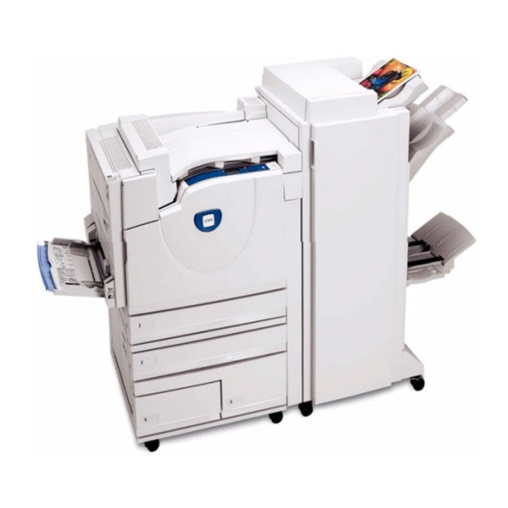
Phaser 7760 per selected model. EN 300 489-3 V1.3.1 The Phaser 7760 is an A3 size, tandem laser color printer, which can print at 35 pages per minute (ppm) color and 45 ppm monochrome. The maximum print resolution are 1200 dpi x This product, if used properly in accordance with the user’s instructions, is neither dangerous... -
Page 18: Phaser 7760 Printer Configurations
Professional Finisher N/A Optional Optional Phaser Match Optional Standard Standard PhaserCal Standard Standard Standard Warranty One-year On-site Warranty, Xerox Total Satisfaction Guarantee Figure 2 Front-Left View Introduction Revised January 2010 Phaser 7760 Printer Configurations, Parts of the Phaser 7760 Color Laser Printer... - Page 19 Finisher Upper Output Tray Tray 1 (MPT) Finisher Stacker Output Tray Finisher Booklet Output Tray Cover 5 (Finisher Door 5) Figure 4 2500-Sheet High-Capacity Feeder Figure 3 Rear View Revised Introduction January 2010 Parts of the Printer Phaser 7760 Color Laser Printer...
-
Page 20: Phaser 7760 Control Panel Configuration
Displays a help message with information about the printer, such as Printer Status, Error Messages, and Maintenance Information. Figure 1 Control Panel Introduction Revised January 2010 Parts of the Printer, Phaser 7760 Control Panel Con- Phaser 7760 Color Laser Printer... -
Page 21: Image Processor Board And Rear Panel Host Interface
Enter Service Diagnostics Menu BACK+INFO Figure 1 Image Processor Board Hard Drive USB Connector Ethernet Connector Config Card NVRAM Heat Sink RAM (DDR2) Health LEDs Revised Introduction January 2010 Phaser 7760 Control Panel Configuration, Image Phaser 7760 Color Laser Printer xvii... -
Page 22: Printer Options
Fuser Unit 100,000 pages Belt Cleaner Assembly 100,000 pages PhaserCal software is a subset of PhaserMatch and comes standard on all Phaser 7760 con- Imaging Unit 35,000 pages figurations. PhaserMatch is standard on Phaser 7760DX and 7760GX configurations, and Waste Toner Cartridge 27,000 pages optional for the Phaser 7760DN. -
Page 23: Specifications
Paper Feed Roller Kit (3 rollers/Tray) 280,000 feeds per tray (1 set of 3 rollers require for each tray) Characteristic Specifications Printing Process The Phaser 7760 printer uses a ROS laser with an electropho- Table 4 CRUs and Consumables tographic four-color (CMYK) tandem architecture. Name Part Number Image System Discharge the image area with ROS laser beam. - Page 24 730 mm (28.7 in.) (without booklet) 870 mm (34.3 in.) (with booklet) Weight 60 kg (132.1 lbs.) (without booklet) 90 kg (198.1 lbs.) (with booklet) Figure 2 Printer & Finisher Minimum Clearances Introduction Revised January 2010 Specifications Phaser 7760 Color Laser Printer...
- Page 25 The printer must not be tipped or tilted more than 5 mm as in Figure These specifications apply to any Phaser 7760 printer used as a table-top printer, without a lower tray assembly or cart. There are 4 feet on the bottom of the printer. The right hand side of the printer is more susceptible to problems due to foot placement.
- Page 26 Up to 11” 2nd Side: 5 mm +/- 2.4 mm 305 mm (3.95- Guaranteed Image Area Paper Size: 297 mm x 1194 mm (11.7 in. x 47.0 in.) 12.00 in) Introduction Revised January 2010 Specifications xxii Phaser 7760 Color Laser Printer...
-
Page 27: Prohibited Media
MPT Only Banner** MPT Only Special All Trays See Note * Xerox does not guarantee Extra Thick Card Stock (over 220 g/m2). ** Banner is size and not a media type. Revised Introduction January 2010 Specifications Phaser 7760 Color Laser Printer... -
Page 28: Glossary Of Terms
Electrostatic Discharge. A transfer of charge between bodies at different electro- Offset Catch Tray static potential. Original equipment manufacturer Field Engineer On-going Maintenance Fast Scan (direction) - Inboard-to Outboard Over Head Paper (Transparency) Introduction Revised January 2010 Glossary of Terms xxiv Phaser 7760 Color Laser Printer... - Page 29 Unscheduled Maintenance User Interface Universal Serial Bus With - indicates machine condition where specified condition is present Without - indicates machine condition where specified condition is not present Revised Introduction January 2010 Glossary of Terms Phaser 7760 Color Laser Printer...
- Page 30 Introduction Revised January 2010 Glossary of Terms xxvi Phaser 7760 Color Laser Printer...
- Page 31 1 Service Call Procedures Service Call Procedures....................Detailed Maintenance Activities (High Frequency Service Items (HFSI)) ....... Cleaning Procedures....................... Cleaning Materials ......................Common Tools ........................ Revised Service Call Procedures January 2010 Phaser 7760 Color Laser Printer...
- Page 32 Service Call Procedures Revised January 2010 Phaser 7760 Color Laser Printer...
-
Page 33: Service Call Procedures
Clean all rubber rollers with a lint-free cloth, dampered slightly with cold water and mild detergent. Inspect the interior of the printer for damaged wires, loose connectors, toner leakage, and damaged or obviously worn parts. Revised Service Call Procedures January 2010 Service Call Procedures Phaser 7760 Color Laser Printer... -
Page 34: Detailed Maintenance Activities (High Frequency Service Items (Hfsi))
• Finisher - Check the paper path for debris or damage. Clean the Finisher with a dry lint- free cloth. Service Call Procedures Revised January 2010 Detailed Maintenance Activities, Cleaning Proce- Phaser 7760 Color Laser Printer... -
Page 35: Cleaning Materials
Scribe Tool 600T41913 Magnetic pickup 600T41911 Eye Loop 600T42008 Flash Light 600T1824 Brush 600T41901 Tester Lead Wire (red) 600T 9583 Tester Lead Wire (black) 600T2030 Revised Service Call Procedures January 2010 Cleaning Materials, Common Tools Phaser 7760 Color Laser Printer... - Page 36 Service Call Procedures Revised January 2010 Cleaning Materials, Common Tools Phaser 7760 Color Laser Printer...
- Page 37 004-322 Main Motor Fail ....................2-29 004-323 Black Imaging Unit Motor Fail ................2-29 004-331 Engine Control Board Fuse F1 Open..............2-30 004-332 Engine Control Board Fuse F2 Open..............2-31 Revised Status Indicator RAP’s January 2010 Phaser 7760 Color Laser Printer...
- Page 38 009-910 Black Imaging Unit Type Mismatch..............2-164 008-626 Regicon Sample Block (A1 Patch-front) ............2-120 009-911 Cyan Imaging Unit Type Mismatch ..............2-165 008-627 Regicon Sample Lateral (A1 Patch-rear) ............2-120 Status Indicator RAP’s Revised January 2010 Phaser 7760 Color Laser Printer...
- Page 39 012-162 H-Transport Exit Sensor On Jam ..............2-223 012-916 Stapler NG ......................2-314 012-171 Top Tray Exit Sensor On Jam................2-225 012-920 Paper at Gate Sensor (Top Tray Job)............... 2-316 Revised Status Indicator RAP’s January 2010 Phaser 7760 Color Laser Printer...
- Page 40 024-947 Tray 3 Out of Place ................... 2-358 024-948 Tray 4 Out of Place ................... 2-359 024-949 Tray 5 Out of Place ................... 2-359 024-950 Tray 2 No Paper Sensor ................... 2-360 Status Indicator RAP’s Revised January 2010 Phaser 7760 Color Laser Printer...
- Page 41 If the problem continues, replace the Engine Control Board (MCU PWB) 13.1). Check installation of the Cover/Actuator. Figure 3 001-300 Left Cover Interlock Switch Location Figure 1 001-300 Left Cover Interlock Switch Revised Status Indicator RAP’s January 2010 001-300 Left Cover (Door A) Open Phaser 7760 Color Laser Printer...
- Page 42 Replace the I/F PWB 9.1). If the problem continues, replace the Engine Control Board (MCU PWB) 13.1). Check installation of the Cover/Actuator 10.1). Status Indicator RAP’s Revised January 2010 001-301 Left Lower Cover (Door B) Open, 001-302 Phaser 7760 Color Laser Printer...
- Page 43 Figure 1 001-302 Front Cover/Right Cover Interlock Figure 1 001-303 Tray Module LH Cover Interlock Switch Figure 2 001-302 Front Interlock Switch Location Revised Status Indicator RAP’s January 2010 001-302 Front Cover Door, 001-303 Tray Module Phaser 7760 Color Laser Printer...
- Page 44 Check the Cover Actuator and Cover installation. If there is no problem, replace the Engine Control Board (MCU PWB) 13.1). Figure 1 001-306 Duplex Cover Interlock Switch Status Indicator RAP’s Revised January 2010 001-306 Duplex Door, 001-540.01 Phaser 7760 Color Laser Printer...
- Page 45 Adjust the Paper Guides against paper. Adjust Paper Guides against paper. Go to RAP 007-271, Tray 3 Size Sensor. Go to RAP 007-276, Tray 4 Size Sensor. Revised Status Indicator RAP’s January 2010 001-540.02, 001-540.03 Phaser 7760 Color Laser Printer...
- Page 46 The paper guides in Tray 5 are adjusted against paper. Go to RAP 007-274, Tray 1 Size Sensor. Adjust the Paper Guides against paper. Go to RAP 007-277, Tray 5 Size Sensor. Status Indicator RAP’s Revised January 2010 001-540.04, 001-540.05 2-10 Phaser 7760 Color Laser Printer...
- Page 47 A4 LEF 1.31 8.5x13 SEF 2.53 B4 SEF 1.23 8K SEF 1.33 A4 SEF 1.12 8.5x11 SEF 1.72 B5 SEF 1.92 16K LEF 2.13 8x10 SEF 1.93 Revised Status Indicator RAP’s January 2010 001-545.01 Phaser 7760 Color Laser Printer 2-11...
- Page 48 B5 or 16K LEF 3.18 B5 or 8x10 SEF 2.87 8.5x11 SEF 2.57 -------------------- 2.15 B4 or 8K SEF 1.98 A4 SEF 1.67 8.5x14 SEF 1.37 -------------------- 0.91 Status Indicator RAP’s Revised January 2010 001-545.02 2-12 Phaser 7760 Color Laser Printer...
- Page 49 Tray 4 Paper Size Sensor 16.1). Table 1 Tray 4 Size Sensor Values Paper Size Voltage No Tray 4.78 B5 LEF 3.19 A4 LEF 0.46 8.5x11 SEF 0.46 Revised Status Indicator RAP’s January 2010 001-545.03 Phaser 7760 Color Laser Printer 2-13...
- Page 50 Tray 5 Paper Size Sensor 16.1). Table 1 Tray 5 Size Sensor Values Paper Size Voltage No Tray 4.78 B5 LEF 3.19 A4 LEF 0.46 8.5x11 SEF 0.46 Status Indicator RAP’s Revised January 2010 001-545.04 2-14 Phaser 7760 Color Laser Printer...
- Page 51 002-707 Control Panel Button Fail Control Panel button failed. Procedure Remove the Control Panel (REP 1.15) and check electrical connections. If connections are good, replace the Control Panel 10.2). Revised Status Indicator RAP’s January 2010 002-707 Phaser 7760 Color Laser Printer 2-15...
- Page 52 Status Indicator RAP’s Revised January 2010 002-707 2-16 Phaser 7760 Color Laser Printer...
- Page 53 Go to the +5 VDC Wirenets to troubleshoot. Replace the following in sequence: • Tray Module PWB 15.9) • Engine Control Board (MCU PWB) 13.1) Go to the appropriate RAP. Revised Status Indicator RAP’s January 2010 003-578, 003-587 Phaser 7760 Color Laser Printer 2-17...
- Page 54 Go to RAP 007-281, Tray (2, 3, 4, 5) Lift Failure. Go to RAP 007-271, Tray 3 Paper Size Sensor. Go to RAP 007-276, Tray 4 Paper Size Sensor. Status Indicator RAP’s Revised January 2010 003-588, 003-589 2-18 Phaser 7760 Color Laser Printer...
- Page 55 Check for fault(s) 007-277, 007-293. There is a 007-277 fault declared. Go to RAP 007-281, Tray (2, 3, 4, 5) Lift Failure. Go to RAP 007-277, Tray 5 Paper Size Sensor. Revised Status Indicator RAP’s January 2010 003-590, 003-594 Phaser 7760 Color Laser Printer 2-19...
- Page 56 Ensure Tray 2 is closed. Turn the printer power Off, then On. The problem continues. Return to Service Call Procedures. Go to RAP 007-270, Tray 2 Paper Size Sensor. Status Indicator RAP’s Revised January 2010 003-777, 003-946 2-20 Phaser 7760 Color Laser Printer...
- Page 57 The machine is equipped with a 3TM. Go to RAP 007-276, Tray 4 Paper Size Sensor (TTM). Go to RAP 007-272, Tray 4 Paper Size Sensor (3TM). Revised Status Indicator RAP’s January 2010 003-947, 003-948 Phaser 7760 Color Laser Printer 2-21...
- Page 58 Go to RAP 007-277, Tray 5 Paper Size Sensor (TTM). Go to RAP 007-273, Tray 5 Paper Size Sensor (3TM). Figure 1 003-950 Tray 2 No Paper Sensor Status Indicator RAP’s Revised January 2010 003-949, 003-950 2-22 Phaser 7760 Color Laser Printer...
- Page 59 Figure 1 003-951 Tray 3 No Paper Sensor (TTM) Figure 2 003-952 Tray 4 No Paper Sensor (3TM) Figure 2 003-951 Tray 3 No Paper Sensor (3TM) Revised Status Indicator RAP’s January 2010 003-951, 003-952 Phaser 7760 Color Laser Printer 2-23...
- Page 60 Figure 1 003-954 Tray 1 (MPT) No Paper Sensor Figure 1 003-953 Tray 5 No Paper Sensor (TTM) Figure 2 003-953 Tray 5 No Paper Sensor (3TM) Status Indicator RAP’s Revised January 2010 003-953, 003-954 2-24 Phaser 7760 Color Laser Printer...
- Page 61 Load the correct size paper and return to Service Call Procedures. Go to RAP 007-274, Tray 1 Paper Size Sensor. Go to RAP 007-270, Tray 2 Paper Size Sensor. Revised Status Indicator RAP’s January 2010 003-958, 003-959 Phaser 7760 Color Laser Printer 2-25...
- Page 62 Go to RAP 007-271, Tray 3 Paper Size Sensor. Go to RAP 007-272 (Tray 4 Paper Size Sensor - 3TM) or RAP 007-276 (Tray 4 Paper Size Sen- sor - TTM). Status Indicator RAP’s Revised January 2010 003-960, 003-961 2-26 Phaser 7760 Color Laser Printer...
- Page 63 (Tray 5 Paper Size Sensor - 3TM) or RAP 007-277 (Tray 5 Paper Size Sen- Go to RAP 007-274, Tray 1 Paper Size Sensor. sor - TTM). Revised Status Indicator RAP’s January 2010 003-962, 003-985 Phaser 7760 Color Laser Printer 2-27...
- Page 64 Status Indicator RAP’s Revised January 2010 003-962, 003-985 2-28 Phaser 7760 Color Laser Printer...
- Page 65 Is the frequency between J235-7 between Replace the Black Go to step 6. 1KHz and 1.3 KHz? Imaging Unit Motor (REP 4.4). Revised Status Indicator RAP’s January 2010 004-322, 004-323 Phaser 7760 Color Laser Printer 2-29...
- Page 66 • P400, pin 1 • P402, pin 6 • P403, pin B1 • P404, pin A6, pin A8, pin A10, pin A12, pin B2 Status Indicator RAP’s Revised January 2010 004-323, 004-331 2-30 Phaser 7760 Color Laser Printer...
- Page 67 • P404, pin A4 • P402, pin 6 • P406, pin 9 • P403, pin B1, pin B17 • P404, pin A6, pin A10, pin B2 Revised Status Indicator RAP’s January 2010 004-332, 004-333 Phaser 7760 Color Laser Printer 2-31...
- Page 68 Fuse to open again if replaced. • P400, pin 4 • P531, pin 3 • P539, pin A8 Status Indicator RAP’s Revised January 2010 004-334, 004-335 2-32 Phaser 7760 Color Laser Printer...
- Page 69 P536, pin 10, pin 11 • P537, pin 6, pin 11 • P539, pin A6 • P540, pin B3, pin B4 • P541, pin A1, pin B1, pin B2 Revised Status Indicator RAP’s January 2010 004-336, 004-337 Phaser 7760 Color Laser Printer 2-33...
- Page 70 P541, pin A8, pin A9, pin B5 error. Control Board • P543, pin 7, pin 9, pin 11 (MCU PWB) (REP Did this clear the error? 1.2). Status Indicator RAP’s Revised January 2010 004-338, 004-340 2-34 Phaser 7760 Color Laser Printer...
- Page 71 Image Processor Board. NVRAM). (MCU PWB) (REP 1.2) or the Image Check the Interlock voltage. Processor Board Is the voltage +5VDC? (REP 1.12). Figure 1 004-341 Printer Logic Failure Revised Status Indicator RAP’s January 2010 004-341 Phaser 7760 Color Laser Printer 2-35...
- Page 72 Replace the Engine Return to Service the problem continue? Control Board Call Procedures. problem continues. Control Board Call Procedures. (MCU PWB) (REP (MCU PWB) (REP 1.2). 1.2). Status Indicator RAP’s Revised January 2010 004-342, 004-343 2-36 Phaser 7760 Color Laser Printer...
- Page 73 HVPS Control PWB • HVPS Control PWB P/J574-7 to MCU (REP 1.7). PWB P/J411-3 • HVPS Control PWB P/J574-6 to MCU PWB P/J411-4 Is the wiring OK? Revised Status Indicator RAP’s January 2010 004-344, 004-345, 004-561 Phaser 7760 Color Laser Printer 2-37...
- Page 74 It may be necessary to query the user for additional information as to likely causes. Table 2 Procedure Step Actions and Questions Have the Accumulator Belt shipping Go to step 2. Remove the restrains been completely removed? restraints. Status Indicator RAP’s Revised January 2010 004-345, 004-561, 004-346, 004-347 2-38 Phaser 7760 Color Laser Printer...
- Page 75 Partially remove the Accumulator Belt Go to step 14. Go to step 7. Assembly. Manually rotate the Drive Gear clock- wise. Does the Belt turn freely? Revised Status Indicator RAP’s January 2010 004-346, 004-347 Phaser 7760 Color Laser Printer 2-39...
- Page 76 Board (MCU PWB) (REP 1.2) Figure 2 004-346, 004-347 IBT Motor Figure 1 004-346, 004-347 IBT Home Sensor Figure 3 004-346, 004-347 IBT Edge Sensor Status Indicator RAP’s Revised January 2010 004-346, 004-347 2-40 Phaser 7760 Color Laser Printer...
- Page 77 > hold the Up and Down buttons simultaneously > Run Service Diag- nostics > OK. Run the Belt Edge Sen- sor test. Is the result OK? Revised Status Indicator RAP’s January 2010 004-346, 004-347, 004-348 Phaser 7760 Color Laser Printer 2-41...
- Page 78 > hold the Up and Down buttons Board (MCU PWB) simultaneously > Run Service Diag- (REP 1.2). nostics > OK. Run the Steering Motor test. Does the Motor run? Status Indicator RAP’s Revised January 2010 004-348 2-42 Phaser 7760 Color Laser Printer...
- Page 79 Figure 2 004-348 IBT Steering Motor Figure 1 004-348 IBT Belt Edge Sensor Revised Status Indicator RAP’s January 2010 004-348 Phaser 7760 Color Laser Printer 2-43...
- Page 80 If the problem continues, turn the printer power Off, then On. Again, turn the printer power Off, then On. Perform the job again. If the problem continues, perform Service Diagnostics. Status Indicator RAP’s Revised January 2010 004-349, 004-350 2-44 Phaser 7760 Color Laser Printer...
- Page 81 If the problem continues, turn the printer power Off, then On. If the problem continues, turn the printer power Off, then On. If the problem continues, perform Service Diagnostics. If the problem continues, perform Service Diagnostics. Revised Status Indicator RAP’s January 2010 004-351, 004-352 Phaser 7760 Color Laser Printer 2-45...
- Page 82 If the problem continues, turn the printer power Off, then On. If the problem continues, turn the printer power Off, then On. If the problem continues, perform Service Diagnostics. If the problem continues, perform Service Diagnostics. Status Indicator RAP’s Revised January 2010 004-353, 004-354 2-46 Phaser 7760 Color Laser Printer...
- Page 83 (REP 1.8). While running the Imaging Unit Motor (REP 4.4). test, check the voltage at J535-7. Is the voltage +5 VDC while the test is running? Revised Status Indicator RAP’s January 2010 004-358, 004-361 Phaser 7760 Color Laser Printer 2-47...
- Page 84 Did this clear the error? trol Board (MCU PWB) (REP 1.2) Image Proces- sor Board (REP 1.12) Figure 1 004-361 Imaging Unit Motor (Y, M, C) Status Indicator RAP’s Revised January 2010 004-361, 004-362 2-48 Phaser 7760 Color Laser Printer...
- Page 85 Figure 1 004-363 Imaging Unit Motor K Is the frequency between J535-8 and Replace the Black Go to step 6. ground between 1 KHz and 1.3 KHz? Imaging Unit Drive Motor (REP 4.4). Revised Status Indicator RAP’s January 2010 004-363 Phaser 7760 Color Laser Printer 2-49...
- Page 86 Step Actions and Questions Cycle power the printer to clear the Complete. Replace the Engine error. Control Board (MCU PWB) (REP Did the error clear? 1.2). Status Indicator RAP’s Revised January 2010 004-371, 004-375 2-50 Phaser 7760 Color Laser Printer...
- Page 87 Repair the open circuit between J590-1 on the AC Drive PWB and J412-19 on the Control Board (MCU PWB). Replace the Engine Control Board (MCU PWB) 13.1). Revised Status Indicator RAP’s January 2010 004-376 Phaser 7760 Color Laser Printer 2-51...
- Page 88 If the problem continues, replace the Engine Control Board (MCU PWB) NVRAM 13.1). If the problem continues, replace the Engine Control Board (MCU PWB) NVRAM 13.1). Status Indicator RAP’s Revised January 2010 004-414, 004-415 2-52 Phaser 7760 Color Laser Printer...
- Page 89 If the problem continues, replace the Engine Control Board (MCU PWB) NVRAM 13.1). If the problem continues, replace the Engine Control Board (MCU PWB) NVRAM 13.1). Revised Status Indicator RAP’s January 2010 004-417, 004-420 Phaser 7760 Color Laser Printer 2-53...
- Page 90 Careful replacement of the MCU NVRAM PWB is important to avoid serious machine failure. If the problem continues, replace the Engine Control Board (MCU PWB) NVRAM 13.1). Status Indicator RAP’s Revised January 2010 004-421, 004-435 2-54 Phaser 7760 Color Laser Printer...
- Page 91 Replace the Engine Control Board (MCU PWB) 13.1). If the problem continues, replace I/F PWB 9.1). If the problem continues, replace IBT Steering Motor 1.3). Repair broken wire and bad connection. Revised Status Indicator RAP’s January 2010 004-605, 004-640 Phaser 7760 Color Laser Printer 2-55...
- Page 92 13.1). If the problem continues, replace the I/F PWB 9.1). If the problem continues, replace the IBT Steering Motor 1.3). Repair broken wire and bad connection. Status Indicator RAP’s Revised January 2010 004-640, 004-641 2-56 Phaser 7760 Color Laser Printer...
- Page 93 If the problem continues, replace the IBT Steering Motor 1.3). Repair broken wire and bad connection. Check IBT Belt installation (REP 9.22). If the check is good, replace MCU PWB 13.1). Revised Status Indicator RAP’s January 2010 004-641, 004-642 Phaser 7760 Color Laser Printer 2-57...
- Page 94 Return to Service Call Procedures. Replace the Engine Control Board (MCU PWB) 13.1) Figure 1 004-642 IBT Belt Edge Sensor Figure 2 004-642 IBT Steering Motor Status Indicator RAP’s Revised January 2010 004-642, 004-650 2-58 Phaser 7760 Color Laser Printer...
- Page 95 Fig- replacing the Laser ure 10 Unit.) If the problem per- sists, replace the Engine Control Board (MCU PWB) (REP 1.2). Figure 1 006-372 Polygon Motor Control Revised Status Indicator RAP’s January 2010 006-372 Phaser 7760 Color Laser Printer 2-59...
- Page 96 Did this fix the problem? replacing the Laser Unit.) If the problem per- sists, replace the Engine Control Board (MCU PWB) (REP 1.2). Figure 1 006-380 ROS SOS Y Status Indicator RAP’s Revised January 2010 006-380 2-60 Phaser 7760 Color Laser Printer...
- Page 97 Figure 3 006-380 ROS SOS M Figure 2 006-380 ROS SOS C Revised Status Indicator RAP’s January 2010 006-380 Phaser 7760 Color Laser Printer 2-61...
- Page 98 Turn the printer power Off, then On. The problem continues. Return to Service Call Procedures. Replace the Engine Control Board (MCU PWB) 13.1). Figure 4 006-380 ROS SOS K Status Indicator RAP’s Revised January 2010 006-380, 006-385 2-62 Phaser 7760 Color Laser Printer...
- Page 99 Ensure that the connectors shown in the circuit diagrams (Figure Figure Figure are securely connected and that the wires are not damaged. • If the problem persists, replace the Tray Module PWB 16.15). Revised Status Indicator RAP’s January 2010 007-104 Phaser 7760 Color Laser Printer 2-63...
- Page 100 • If these checks are OK, replace the I/F PWB 9.1). • If the problem persists, replace the Engine Control Board (MCU PWB) 13.1). Status Indicator RAP’s Revised January 2010 007-104, 007-105 2-64 Phaser 7760 Color Laser Printer...
- Page 101 3. Check the wires from the Tray Module PWB to the Takeaway Motor 1 for an open circuit. If the wires are good, replace the Takeaway Motor 1 15.9) Figure 2 007-105 Tray 2 Feed/Lift Motor Revised Status Indicator RAP’s January 2010 007-105, 007-110 Phaser 7760 Color Laser Printer 2-65...
- Page 102 If these checks are OK, replace the Tray Module PWB (PL 16.15 - TTM or PL 15.9 - 3TM). Figure 2 007-110 Tray 3 Feed/Lift Motor Figure 1 007-110 Takeaway Sensor Status Indicator RAP’s Revised January 2010 007-110 2-66 Phaser 7760 Color Laser Printer...
- Page 103 Ensure that the connectors shown in the circuit diagrams (Figure Figure Figure are securely connected and that the wires are not damaged. • If these checks are OK, replace the Tray Module PWB 16.15). Revised Status Indicator RAP’s January 2010 007-110, 007-115 Phaser 7760 Color Laser Printer 2-67...
- Page 104 Figure 1 007-115 Tray 4 Feedout Sensor Figure 3 007-115 Takeaway Motor 1 Figure 2 007-115 Tray 4 Feed/Lift Motor Status Indicator RAP’s Revised January 2010 007-115 2-68 Phaser 7760 Color Laser Printer...
- Page 105 • If these checks are OK, replace the Tray Module PWB 15.9). Figure 2 007-117 Tray 4 Feed/Lift Motor Revised Status Indicator RAP’s January 2010 007-117 Phaser 7760 Color Laser Printer 2-69...
- Page 106 Ensure that the connectors shown in the circuit diagrams (Figure Figure Figure are securely connected and that the wires are not damaged. • If these checks are OK, replace the Tray Module PWB 16.15). Status Indicator RAP’s Revised January 2010 007-117, 007-119 2-70 Phaser 7760 Color Laser Printer...
- Page 107 Figure 1 007-119 Tray 5 Feedout Sensor Figure 3 007-119 Takeaway Motor 2 Figure 2 007-119 Tray 5 Feed/Lift Motor Revised Status Indicator RAP’s January 2010 007-119 Phaser 7760 Color Laser Printer 2-71...
- Page 108 • If these checks are OK, replace the Tray Module PWB 15.9). Figure 2 007-120 Tray 5 Feed/Lift Motor Status Indicator RAP’s Revised January 2010 007-120 2-72 Phaser 7760 Color Laser Printer...
- Page 109 Figure 3 007-120 Takeaway Motor 1 the Tray 5 Feed Out Sensor 16.5). • If the problem continues, replace the Tray Module PWB 16.15). Figure 1 007-122 Tray 5 Feedout Sensor Revised Status Indicator RAP’s January 2010 007-120, 007-122 Phaser 7760 Color Laser Printer 2-73...
- Page 110 • P669-4 to J534A-12 (MCU PWB) • P669-5 to J534A-11 (REP 1.2) • P669-6 to J534A-10 Do all checks indicate continuity? Figure 1 007-250 Tray Module PWB Status Indicator RAP’s Revised January 2010 007-250 2-74 Phaser 7760 Color Laser Printer...
- Page 111 B5 or 8x10 SEF 1.92 8.5x11 SEF 1.71 B4 or 8K SEF 1.32 A4 SEF 1.24 8.5x14 SEF 0.92 A4 LEF 0.51 8.5x11 LEF 0.32 A5 or 5.5x8.5 SEF 0.12 Revised Status Indicator RAP’s January 2010 007-270 Phaser 7760 Color Laser Printer 2-75...
- Page 112 B5 or 16K LEF 3.18 B5 or 8x10 SEF 2.87 8.5x11 SEF 2.57 B4 or 8K SEF 1.98 A4 SEF 1.67 8.5x14 SEF 1.37 A4 LEF 0.77 Status Indicator RAP’s Revised January 2010 007-271 2-76 Phaser 7760 Color Laser Printer...
- Page 113 Replace the Tray 4 Paper Size Sensor 16.1). 8.5x14SEF 1.37 • If the problem persists, replace the Tray Module PWB 15.9). A4LEF 0.77 8.5x11LEF 0.47 A5 or 5.5x8.5SEF 0.17 Revised Status Indicator RAP’s January 2010 007-272 Phaser 7760 Color Laser Printer 2-77...
- Page 114 Replace the Tray 5 Paper Size Sensor 16.1). 8.5x14SEF 1.37 • If the problem persists, replace the Tray Module PWB 15.9). A4LEF 0.77 8.5x11LEF 0.47 A5 or 5.5x8.5SEF 0.17 Status Indicator RAP’s Revised January 2010 007-273 2-78 Phaser 7760 Color Laser Printer...
- Page 115 Table 1 Tray 4 Size Sensor Values Figure 1 007-274 Tray 1 (MPT) Paper Size Sensor Paper Size Voltage No Tray 4.78 B5 LEF 4.11 8.5x11 LEF 2.23 A4 LEF 1.59 Revised Status Indicator RAP’s January 2010 007-274, 007-276 Phaser 7760 Color Laser Printer 2-79...
- Page 116 Paper Size Sensor 16.1). Table 1 Tray 5 Size Sensor Values Paper Size Voltage No Tray 4.78 B5 LEF 4.11 8.5x11 LEF 2.23 A4 LEF 1.59 Status Indicator RAP’s Revised January 2010 007-276, 007-277 2-80 Phaser 7760 Color Laser Printer...
- Page 117 Control Board mittent problem. If (MCU PWB) (REP the problem returns, 1.2). replace in order: Tray Level Sensor Engine Con- trol Board (MCU PWB) (REP 1.2) Revised Status Indicator RAP’s January 2010 007-277, 007-281 Phaser 7760 Color Laser Printer 2-81...
- Page 118 (MCU PWB) (REP 1.2) Remove and then reseat the problem Go to step 8. Go to step 9. tray. Listen for the Motor. Does the Lift Motor operate? Status Indicator RAP’s Revised January 2010 007-281 2-82 Phaser 7760 Color Laser Printer...
- Page 119 (MCU PWB) (REP 1.2) Figure 2 007-281 Tray 2 Level Sensor Figure 3 007-281 +24 VDC to the Tray Module PWB Figure 1 007-281 Tray 2 Lift/Feed Motor Revised Status Indicator RAP’s January 2010 007-281 Phaser 7760 Color Laser Printer 2-83...
- Page 120 Control Board mittent problem. If (MCU PWB) (REP the problem returns, 1.2). replace in order: Tray Level Sensor Engine Con- trol Board (MCU PWB) (REP 1.2) Status Indicator RAP’s Revised January 2010 007-281, 007-282 2-84 Phaser 7760 Color Laser Printer...
- Page 121 (MCU PWB) (REP 1.2) Remove and then reseat the problem Go to step 8. Go to step 9. tray. Listen for the Motor. Does the Lift Motor operate? Revised Status Indicator RAP’s January 2010 007-282 Phaser 7760 Color Laser Printer 2-85...
- Page 122 (MCU PWB) (REP 1.2) Figure 2 007-282 Tray 3 Level Sensor Figure 3 007-282 +24 VDC to the Tray Module PWB Figure 1 007-282 Tray 3 Lift/Feed Motor Status Indicator RAP’s Revised January 2010 007-282 2-86 Phaser 7760 Color Laser Printer...
- Page 123 Control Board mittent problem. If (MCU PWB) (REP the problem returns, 1.2). replace in order: Tray Level Sensor Engine Con- trol Board (MCU PWB) (REP 1.2) Revised Status Indicator RAP’s January 2010 007-282, 007-283 Phaser 7760 Color Laser Printer 2-87...
- Page 124 (MCU PWB) (REP 1.2) Remove and then reseat the problem Go to step 8. Go to step 9. tray. Listen for the Motor, does the Lift Motor operate? Status Indicator RAP’s Revised January 2010 007-283 2-88 Phaser 7760 Color Laser Printer...
- Page 125 (MCU PWB) (REP 1.2) Figure 2 007-283 Tray 4 Level Sensor Figure 3 007-283 +24 VDC to the Tray Module PWB Figure 1 007-283 Tray 4 Feed/Lift Motor Revised Status Indicator RAP’s January 2010 007-283 Phaser 7760 Color Laser Printer 2-89...
- Page 126 Control Board mittent problem. If (MCU PWB) (REP the problem returns, 1.2). replace in order: Tray Level Sensor Engine Con- trol Board (MCU PWB) (REP 1.2) Status Indicator RAP’s Revised January 2010 007-283, 007-284 2-90 Phaser 7760 Color Laser Printer...
- Page 127 (MCU PWB) (REP 1.2) Remove and then reseat the problem Go to step 8. Go to step 9. tray. Listen for the Motor, does the Lift Motor operate? Revised Status Indicator RAP’s January 2010 007-284 Phaser 7760 Color Laser Printer 2-91...
- Page 128 Figure 3 007-284 +24 VDC to the Tray Module PWB Figure 1 007-284 Tray 5 Feed/Lift Motor Figure 4 007-284 +5 VDC to the Tray Module PWB Figure 2 007-284 Tray 5 Level Sensor Status Indicator RAP’s Revised January 2010 007-284 2-92 Phaser 7760 Color Laser Printer...
- Page 129 Replace the Tray 4 Level Sensor 2.4). • If these checks ar e OK, replace the Tray Module PWB 16.15). Figure 2 007-291 Tray 4 Level Sensor (TTM) Revised Status Indicator RAP’s January 2010 007-291 Phaser 7760 Color Laser Printer 2-93...
- Page 130 Replace the Tray 5 Level Sensor 2.4). • If these checks are OK, replace the Tray Module PWB 16.15). Figure 2 007-293 Tray 5 Level Sensor (TTM) Status Indicator RAP’s Revised January 2010 007-293 2-94 Phaser 7760 Color Laser Printer...
- Page 131 1.2) (REP 1.2) Remove and then reseat the problem Go to step 8. Go to step 9. tray. Listen for the Motor, does the Lift Motor operate? Revised Status Indicator RAP’s January 2010 007-397 Phaser 7760 Color Laser Printer 2-95...
- Page 132 Paper-Select Switch Assem- (REP 7.5) Engine Inter- face Board (REP 1.8) Engine Con- trol Board (MCU PWB) (REP 1.2) Figure 1 007-397 Tray 2 Lift/Feed Motor Status Indicator RAP’s Revised January 2010 007-397 2-96 Phaser 7760 Color Laser Printer...
- Page 133 Figure 2 007-397 Tray 2 Level Sensor Figure 4 007-397 Tray 3 Level Sensor Figure 3 007-397 Tray 3 Lift/Feed Motor Figure 5 007-397 Tray 4 Lift/Feed Motor Revised Status Indicator RAP’s January 2010 007-397 Phaser 7760 Color Laser Printer 2-97...
- Page 134 Reset the indicated Tray’s Feed Roller life in the Service Tools menu. Figure 6 007-397 Tray 4 Level Sensor Figure 7 007-397 Tray 5 Lift/Feed Motor Figure 8 007-397 Tray 5 Level Sensor Status Indicator RAP’s Revised January 2010 007-397, 007-401 ~ 007-409 2-98 Phaser 7760 Color Laser Printer...
- Page 135 Ensure the Paper Guides are correctly adjusted. Load the correct size paper. Go to RAP 007-270, Tray 2 Size Sensor. Go to RAP 007-271, Tray 3 Size Sensor. Revised Status Indicator RAP’s January 2010 007-930, 007-931 Phaser 7760 Color Laser Printer 2-99...
- Page 136 Ensure the Paper Guides are correctly adjusted. Load the correct size paper. Go to RAP 007-276, Tray 4 Size Sensor. Go to RAP 007-277, Tray 5 Size Sensor. Status Indicator RAP’s Revised January 2010 007-932, 007-933 2-100 Phaser 7760 Color Laser Printer...
- Page 137 • If the problem persists, replace the Engine Control Board (MCU PWB) 13.1). Figure 1 007-959 OHP Sensor R Revised Status Indicator RAP’s January 2010 007-954, 007-959 Phaser 7760 Color Laser Printer 2-101...
- Page 138 If the problem persists, replace the Engine Control Board (MCU PWB) 13.1). • If the problem persists, replace the I/F PWB 9.1). Figure 1 007-969 Full Paper Stack Figure 1 007-960 OHP Sensor R Status Indicator RAP’s Revised January 2010 007-960, 007-969 2-102 Phaser 7760 Color Laser Printer...
- Page 139 • Replace the Takeaway Sensor 15.10). • If the problem persists, replace the Tray Module PWB 15.9). Figure 2 008-149 Takeaway Motor 1 Revised Status Indicator RAP’s January 2010 008-149 Phaser 7760 Color Laser Printer 2-103...
- Page 140 • Replace the Takeaway Sensor 15.10). • If the problem persists, replace the Tray Module PWB 15.9). Figure 2 008-150 Takeaway Motor 1 Status Indicator RAP’s Revised January 2010 008-150 2-104 Phaser 7760 Color Laser Printer...
- Page 141 • Replace the Takeaway Sensor 16.6). • If the problem persists, replace the Tray Module PWB 16.15). Figure 2 008-151 Takeaway Motor 1 Revised Status Indicator RAP’s January 2010 008-151 Phaser 7760 Color Laser Printer 2-105...
- Page 142 • Replace the Takeaway Sensor 16.6). • If the problem persists, replace the Tray Module PWB 16.15). Status Indicator RAP’s Revised January 2010 008-152 2-106 Phaser 7760 Color Laser Printer...
- Page 143 Ensure that the connectors shown in the circuit diagrams (Figure Figure 2) are securely connected and that the wires are not damaged. • Replace the POB Sensor 2.9). Revised Status Indicator RAP’s January 2010 008-152, 008-164 Phaser 7760 Color Laser Printer 2-107...
- Page 144 Figure 1 008-164 POB Sensor Figure 2 008-164 Registration Clutch Figure 3 008-164 Fuser Exit Switch Status Indicator RAP’s Revised January 2010 008-164 2-108 Phaser 7760 Color Laser Printer...
- Page 145 Figure 4 008-164 Main Motor Revised Status Indicator RAP’s January 2010 008-164 Phaser 7760 Color Laser Printer 2-109...
- Page 146 Ensure that the connectors shown in the circuit diagrams (Figure Figure 2) are securely connected and that the wires are not damaged. • Replace the Registration Sensor 2.6). Figure 1 008-175 Registration Sensor Status Indicator RAP’s Revised January 2010 008-175 2-110 Phaser 7760 Color Laser Printer...
- Page 147 Ensure that the connectors shown in the circuit diagrams (Figure Figure 2) are securely connected and that the wires are not damaged. • Replace the Registration Sensor 2.6). Figure 2 008-176 Takeaway Motor Revised Status Indicator RAP’s January 2010 008-176 Phaser 7760 Color Laser Printer 2-111...
- Page 148 Ensure that the connectors shown in the circuit diagrams (Figure Figure Figure Figure 4) are securely connected and that the wires are not damaged. • If the problem persists, replace the Duplex PWB 12.1). Status Indicator RAP’s Revised January 2010 008-180 2-112 Phaser 7760 Color Laser Printer...
- Page 149 Figure 2 008-180 Duplex Motor Figure 3 008-180 Inverter Reverse Clutch Figure 4 008-180 Duplex Gate Solenoid Revised Status Indicator RAP’s January 2010 008-180 Phaser 7760 Color Laser Printer 2-113...
- Page 150 Close the Duplex Module Cover and remove the Left Upper Cover 2.7). Perform Service Diagnostics. The Duplex Transport Roll 12.1) rotates. Figure 1 008-181 Registration Sensor The Duplex Motor 12.1) energizes. Figure 2 008-181 Duplex Wait Sensor Status Indicator RAP’s Revised January 2010 008-181 2-114 Phaser 7760 Color Laser Printer...
- Page 151 Figure 3 008-181 Duplex Motor Revised Status Indicator RAP’s January 2010 008-181 Phaser 7760 Color Laser Printer 2-115...
- Page 152 Ensure that the connectors shown in the circuit diagrams (Figure Figure 2) are securely connected and that the wires are not damaged. • If the problem persists, replace the Duplex PWB 12.1). Status Indicator RAP’s Revised January 2010 008-184 2-116 Phaser 7760 Color Laser Printer...
- Page 153 Replace the Environment Sensor 1.3). • I/F PWB J404-12 and J255-1 • I/F PWB J404-10 and J255-3 Replace Engine Control Board (MCU PWB) 13.1). Figure 1 008-620 Environmental Sensor Revised Status Indicator RAP’s January 2010 008-620 Phaser 7760 Color Laser Printer 2-117...
- Page 154 Check the IBT Belt and Drum for a scratch or contamination. The check is OK. Replace as required. Replace as required. Perform RegiCon Adjustment procedure 9.10. Perform RegiCon Adjustment procedure 9.10. Status Indicator RAP’s Revised January 2010 008-622, 008-623 2-118 Phaser 7760 Color Laser Printer...
- Page 155 Check the IBT Belt and Drum for a scratch or contamination. The check is OK. Replace as required. Replace as required. Perform RegiCon Adjustment procedure 9.10. Perform RegiCon Adjustment procedure 9.10. Revised Status Indicator RAP’s January 2010 008-624, 008-625 Phaser 7760 Color Laser Printer 2-119...
- Page 156 Check the IBT Belt and Drum for a scratch or contamination. The check is OK. Replace as required. Replace as required. Perform RegiCon Adjustment procedure 9.10. Perform RegiCon Adjustment procedure 9.10. Status Indicator RAP’s Revised January 2010 008-626, 008-627 2-120 Phaser 7760 Color Laser Printer...
- Page 157 Check the IBT Belt and Drum for a scratch or contamination. The check is OK. Perform RegiCon Adjustment procedure 9.10. Replace as required. Perform the RegiCon Skew ADJ 9.9 procedure. Revised Status Indicator RAP’s January 2010 008-628, 008-629 Phaser 7760 Color Laser Printer 2-121...
- Page 158 Check the IBT Belt and Drum for a scratch or contamination. The check is OK. Replace as required. Replace as required. Perform the RegiCon Skew ADJ 9.9 procedure. Perform the RegiCon Skew ADJ 9.9 procedure. Status Indicator RAP’s Revised January 2010 008-630, 008-631 2-122 Phaser 7760 Color Laser Printer...
- Page 159 RAP. • 10-101 Fuser Exit Switch; 010-106 RAP. The display changes for each code. Go to the appropriate paper path fault RAP. Check the machine input voltage. Revised Status Indicator RAP’s January 2010 008-900 Phaser 7760 Color Laser Printer 2-123...
- Page 160 Status Indicator RAP’s Revised January 2010 008-900 2-124 Phaser 7760 Color Laser Printer...
- Page 161 Replace the Devel- Repair or replace ground of the wiring from J-533 to J-232. oper Drive Motor the wiring harness. Is the wiring OK? Assembly (REP 4.3). Revised Status Indicator RAP’s January 2010 009-330, 009-342, 009-343 Phaser 7760 Color Laser Printer 2-125...
- Page 162 Measure the voltage at the Engine Control Board J540B4 while running the 2nd BTR Motor test several times. Does the voltage between +5 VDC and 0 VDC when the test running? Status Indicator RAP’s Revised January 2010 009-342, 009-343 2-126 Phaser 7760 Color Laser Printer...
- Page 163 Figure 2 009-342, 009-343 2nd BTR Retract Motor Revised Status Indicator RAP’s January 2010 009-342, 009-343 Phaser 7760 Color Laser Printer 2-127...
- Page 164 Figure 3 009-342, 009-343 2nd BTR Retract Sensor Status Indicator RAP’s Revised January 2010 009-342, 009-343 2-128 Phaser 7760 Color Laser Printer...
- Page 165 Figure 4 009-342, 009-343 2nd BTR Retract Motor Revised Status Indicator RAP’s January 2010 009-342, 009-343 Phaser 7760 Color Laser Printer 2-129...
- Page 166 Replace the Accu- sive Sensor Proce- mulator Belt Assem- Does the status change between H dure. (REP 9.15). and L? Figure 1 009-348, 009-349 1st BTR Retract Sensor Status Indicator RAP’s Revised January 2010 009-348, 009-349 2-130 Phaser 7760 Color Laser Printer...
- Page 167 Figure 2 009-348, 009-349 1st BTR Retract Motor Figure 3 009-348, 009-349 1st BTR Retract Sensor Revised Status Indicator RAP’s January 2010 009-348, 009-349 Phaser 7760 Color Laser Printer 2-131...
- Page 168 Figure 4 009-348, 009-349 1ST BTR Retract Motor Status Indicator RAP’s Revised January 2010 009-348, 009-349 2-132 Phaser 7760 Color Laser Printer...
- Page 169 > OK. Run the Accumulator trol Board MOB Sensor test. (MCU PWB) (REP 1.2) Is the value H when the Belt Home Marker is NOT under the Belt Home Sensor? Revised Status Indicator RAP’s January 2010 009-350 Phaser 7760 Color Laser Printer 2-133...
- Page 170 Figure 2 009-350 IBT Home Sensor Status Indicator RAP’s Revised January 2010 009-350 2-134 Phaser 7760 Color Laser Printer...
- Page 171 > hold the Up and Down buttons trol Board simultaneously > Run Service Diag- (MCU PWB) nostics > OK. Run the Belt Edge (REP 1.2) Sensor test. Is the result OK? Revised Status Indicator RAP’s January 2010 009-351 Phaser 7760 Color Laser Printer 2-135...
- Page 172 Is the voltage +24 VDC? Board (REP 1.8) Engine Con- trol Board (MCU PWB) (REP 1.2) Figure 1 009-351 IBT Steering Motor Figure 2 009-351 IBT Edge Sensor Status Indicator RAP’s Revised January 2010 009-351 2-136 Phaser 7760 Color Laser Printer...
- Page 173 Engine Control Board. 1.2). necessary. Alternately interrupt the Sensor. Does the voltage measure between +5 and 0 VDC? Figure 1 009-358 Full Toner Sensor Revised Status Indicator RAP’s January 2010 009-358 Phaser 7760 Color Laser Printer 2-137...
- Page 174 OK, replace the Switch - Figure 9 9.8). Engine Control Is the connector damaged? Board (MCU PWB) (REP 1.2). Figure 1 009-360 Yellow Imaging Unit Communication Fail Status Indicator RAP’s Revised January 2010 009-360 2-138 Phaser 7760 Color Laser Printer...
- Page 175 OK, replace the Switch - Figure 9 9.8). Engine Control Is the connector damaged? Board (MCU PWB) (REP 1.2). Figure 1 009-361 Magenta Imaging Unit Communication Fail Revised Status Indicator RAP’s January 2010 009-361 Phaser 7760 Color Laser Printer 2-139...
- Page 176 OK, replace the Switch - Figure 9 9.8). Engine Control Is the connector damaged? Board (MCU PWB) (REP 1.2). Figure 1 009-362 Cyan Imaging Unit Communication Fail Status Indicator RAP’s Revised January 2010 009-362 2-140 Phaser 7760 Color Laser Printer...
- Page 177 OK, replace the Switch - Figure 9 9.8). Engine Control Is the connector damaged? Board (MCU PWB) (REP 1.2). Figure 1 009-363 Black Imaging Unit Communication Fail Revised Status Indicator RAP’s January 2010 009-363 Phaser 7760 Color Laser Printer 2-141...
- Page 178 Magenta = P401B8 Figure 1 009-380, 009-381, 009-382, 009-383 ATC Sensor Y • Cyan = P401A10 Is the voltage between +1 and +3 VDC? Status Indicator RAP’s Revised January 2010 009-380, 009-381, 009-382, 009-383 2-142 Phaser 7760 Color Laser Printer...
- Page 179 Figure 4 009-380, 009-381, 009-382, 009-383 ATC Sensor K Figure 2 009-380, 009-381, 009-382, 009-383 ATC Sensor M Figure 3 009-380, 009-381, 009-382, 009-383 ATC Sensor C Revised Status Indicator RAP’s January 2010 009-380, 009-381, 009-382, 009-383 Phaser 7760 Color Laser Printer 2-143...
- Page 180 6). If the continuity is OK, replace the Engine Control Board (MCU PWB) 13.1). Replace the Black CRUM Antenna PWB 6.1). Replace the Cyan CRUM Antenna PWB 6.1). Status Indicator RAP’s Revised January 2010 009-390, 009-391 2-144 Phaser 7760 Color Laser Printer...
- Page 181 6). If continuity is OK, replace the Engine Control Board (MCU PWB) 13.1). Replace the Magenta CRUM Antenna PWB 6.1). Replace the Yellow CRUM Antenna PWB 6.1). Revised Status Indicator RAP’s January 2010 009-392, 009-393 Phaser 7760 Color Laser Printer 2-145...
- Page 182 Replace the Waste Toner Cartridge. Check the Full Toner Sensor for contaminants. Procedure If the problem persists, go to RAP 009-358, Waste Cartridge Full Toner Sensor Failure. Status Indicator RAP’s Revised January 2010 009-408, 009-409 2-146 Phaser 7760 Color Laser Printer...
- Page 183 There is +5 VDC from J535-7 to J535-6 on the I/F PWB. Refer to the +5 VDC Wirenets (Section 7, Wiring Data, +5.5 VDC Wirenet - Figure and troubleshoot the problem. Revised Status Indicator RAP’s January 2010 009-410 Phaser 7760 Color Laser Printer 2-147...
- Page 184 There is +5 VDC from J535-7 to J535-6 on the I/F PWB. Go to the +5 VDC Wirenets (Section 7, Wiring Data, +5.5 VDC Wirenet - Figure and troubleshoot the problem. Status Indicator RAP’s Revised January 2010 009-411 2-148 Phaser 7760 Color Laser Printer...
- Page 185 There is +5 VDC from J535-7 to J535-3 on the I/F PWB. Go to the +5 VDC Wirenets (Section 7, Wiring Data, +5.5 VDC Wirenets - Figure and troubleshoot the problem. Revised Status Indicator RAP’s January 2010 009-412 Phaser 7760 Color Laser Printer 2-149...
- Page 186 9.3. The Black ATC Sensor check is OK. Go to RAP 009-380, 009-381, 009-382, 009-383, ATC Sensor Failure. After checking that no failures are detected during normal operation, go to call closeout. Status Indicator RAP’s Revised January 2010 009-413 2-150 Phaser 7760 Color Laser Printer...
- Page 187 Replace the Engine Control Board (MCU PWB) 13.1). Replace the Engine Control Board (MCU PWB) 13.1). Return to Service Call Procedures. Return to Service Call Procedures. Revised Status Indicator RAP’s January 2010 009-428, 009-429 Phaser 7760 Color Laser Printer 2-151...
- Page 188 Replace the Engine Control Board (MCU PWB) 13.1). Replace the Engine Control Board (MCU PWB) 13.1). Return to Service Call Procedures. Return to Service Call Procedures. Status Indicator RAP’s Revised January 2010 009-430, 009-431 2-152 Phaser 7760 Color Laser Printer...
- Page 189 009-433 Magenta Imaging Unit Replaced The Y Imaging Unit has been replaced. The M Imaging Unit has been replaced. Procedure Procedure No action required. No action required. Revised Status Indicator RAP’s January 2010 009-432, 009-433 Phaser 7760 Color Laser Printer 2-153...
- Page 190 009-435 Black Imaging Unit Replaced The Cyan Imaging Unit has been replaced. The Black Imaging Unit has been replaced. Procedure Procedure No action required. No action required. Status Indicator RAP’s Revised January 2010 009-434, 009-435 2-154 Phaser 7760 Color Laser Printer...
- Page 191 Replace the Engine Control Board (MCU PWB) 13.1). Replace the Engine Control Board (MCU PWB) 13.1). Return to Service Call Procedures. Return to Service Call Procedures. Revised Status Indicator RAP’s January 2010 009-446, 009-447 Phaser 7760 Color Laser Printer 2-155...
- Page 192 Replace the Engine Control Board (MCU PWB) 13.1). Replace the Engine Control Board (MCU PWB) 13.1). Return to Service Call Procedures. Return to Service Call Procedures. Status Indicator RAP’s Revised January 2010 009-448, 009-449 2-156 Phaser 7760 Color Laser Printer...
- Page 193 Check the wires and connectors. If the check is OK, replace the, replace the ADC Sensor Assembly 1.3). After checking that no failures are detected during normal operation, go to call closeout. Revised Status Indicator RAP’s January 2010 009-451~ 09-459, 009-654 Phaser 7760 Color Laser Printer 2-157...
- Page 194 Figure 1 009-654 ADC Sensor Status Indicator RAP’s Revised January 2010 009-654 2-158 Phaser 7760 Color Laser Printer...
- Page 195 13.1) in sequence. Procedure Disconnect J255. There is 1 Ohm or less measured between P255-3 and P255-4 on the Environment Sensor. Figure 1 009-660 Environmental Sensor Temperature Revised Status Indicator RAP’s January 2010 009-660 Phaser 7760 Color Laser Printer 2-159...
- Page 196 There is +5 VDC from J404-12 on the I/F PWB to GND. Replace the I/F PWB 9.1). If the problem continues, replace the Engine Control Board (MCU PWB) 13.1). Figure 1 009-661 Environmental Sensor Temperature Status Indicator RAP’s Revised January 2010 009-661 2-160 Phaser 7760 Color Laser Printer...
- Page 197 Go to RAP 009-390, New Black Toner Cartridge. Go to RAP 009-391, New Cyan Toner Cartridge. Return to Service Call Procedures. Return to Service Call Procedures. Revised Status Indicator RAP’s January 2010 009-670, 009-671 Phaser 7760 Color Laser Printer 2-161...
- Page 198 Go to RAP 009-392, New Magenta Toner Cartridge. Go to RAP 009-393, New Yellow Toner Cartridge. Return to Service Call Procedures. Return to Service Call Procedures. Status Indicator RAP’s Revised January 2010 009-672, 009-673 2-162 Phaser 7760 Color Laser Printer...
- Page 199 There is 0 VDC from J404B-3 on the MCU PWB to GND. After checking that no failures are detected during normal operation, go to call closeout. Figure 1 009-684 ADC Sensor Revised Status Indicator RAP’s January 2010 009-684 Phaser 7760 Color Laser Printer 2-163...
- Page 200 1). If the check is OK, replace the Black Imaging Unit 4.1). Replace the Engine Control Board (MCU PWB) 13.1). Figure 1 009-910 Black Imaging Unit Communication Status Indicator RAP’s Revised January 2010 009-695, 009-910 2-164 Phaser 7760 Color Laser Printer...
- Page 201 Replace the Engine Control Board (MCU PWB) 13.1). Replace the Engine Control Board (MCU PWB) 13.1). Figure 1 009-912 Magenta Imaging Unit Communication Figure 1 009-911 Cyan Imaging Unit Communication Revised Status Indicator RAP’s January 2010 009-911, 009-912 Phaser 7760 Color Laser Printer 2-165...
- Page 202 6.1). If the problem continues, go RAP 009-410, Yellow Toner Cartridge Near Empty. Replace the Engine Control Board (MCU PWB) 13.1). Figure 1 009-913 Yellow Imaging Unit Communication Status Indicator RAP’s Revised January 2010 009-913, 009-920 2-166 Phaser 7760 Color Laser Printer...
- Page 203 6.1). If the problem continues, go to RAP 009-411, Magenta Replace the Toner Cartridge 6.1). If the problem continues, go to RAP 009-412, Cyan Toner Cartridge Near Empty. Toner Cartridge Near Empty. Revised Status Indicator RAP’s January 2010 009-921, 009-922 Phaser 7760 Color Laser Printer 2-167...
- Page 204 Check the drive system from the Main Drive Motor to the Black Developer Housing for damage. Procedure Replace the Toner Cartridge 6.1). If the problem continues, go to RAP 009-413, Black Toner Cartridge Near Empty. Status Indicator RAP’s Revised January 2010 009-923, 009-924 2-168 Phaser 7760 Color Laser Printer...
- Page 205 Check the connector J408-5 between the MCU PWB and GND. If no problems are found, replace the Engine Control Board (MCU PWB) 13.1). Figure 1 009-925 Waste Toner Cartridge Installation Revised Status Indicator RAP’s January 2010 009-925, 009-926 Phaser 7760 Color Laser Printer 2-169...
- Page 206 Replace the Engine Control Board (MCU PWB) 13.1). Replace the Engine Control Board (MCU PWB) 13.1). Return to Service Call Procedures. Return to Service Call Procedures. Status Indicator RAP’s Revised January 2010 009-927, 009-928 2-170 Phaser 7760 Color Laser Printer...
- Page 207 1). If the check is OK, replace the Engine Control Board (MCU PWB) 13.1). Replace the defective Imaging Unit 4.1). Figure 1 009-930 Black Imaging Unit Communication Revised Status Indicator RAP’s January 2010 009-929, 009-930 Phaser 7760 Color Laser Printer 2-171...
- Page 208 Replace the defective Imaging Unit 4.1). Replace the defective Imaging Unit 4.1). Figure 1 009-931 Cyan Imaging Unit Communication Figure 1 009-932 Magenta Imaging Unit Communication Status Indicator RAP’s Revised January 2010 009-931, 009-932 2-172 Phaser 7760 Color Laser Printer...
- Page 209 1). If the check is OK, replace the Engine Control Board (MCU PWB) 13.1). Replace the defective Imaging Unit 4.1). Figure 1 009-933 Yellow Imaging Unit Communication Revised Status Indicator RAP’s January 2010 009-933 Phaser 7760 Color Laser Printer 2-173...
- Page 210 Status Indicator RAP’s Revised January 2010 009-933 2-174 Phaser 7760 Color Laser Printer...
- Page 211 Ensure that the connectors shown in the circuit diagrams (Figure 1) are securely con- nected and that the wires are not damaged. • If the problem persists, replace the Engine Control Board (MCU PWB) 13.1). Revised Status Indicator RAP’s January 2010 010-105 Phaser 7760 Color Laser Printer 2-175...
- Page 212 13.1). • If the problem persists, replace the Engine Control Board (MCU PWB) 13.1). Figure 1 010-106 Fuser Exit Switch Figure 1 010-110 Fuser Exit Switch Status Indicator RAP’s Revised January 2010 010-106, 010-110 2-176 Phaser 7760 Color Laser Printer...
- Page 213 4) are securely connected and that the wires are not damaged. • If the 10-125 occurs when duplexing, there may be excessive clearance between the Tray Nip Solenoid arm and shaft. Refer to F-001. Revised Status Indicator RAP’s January 2010 010-111, 010-125 Phaser 7760 Color Laser Printer 2-177...
- Page 214 • If the problem persists, replace the Engine Control Board (MCU PWB) 13.1). Figure 1 010-125 Duplex Wait Sensor Figure 2 010-125 Duplex Motor Status Indicator RAP’s Revised January 2010 010-125 2-178 Phaser 7760 Color Laser Printer...
- Page 215 Repair or replace the wiring harness. Measure the resistance between J641-2 J641-3 on the Engine Control Board. Does the resistance measure between 30 K and 190 K Ohms? Revised Status Indicator RAP’s January 2010 010-125, 010-348 Phaser 7760 Color Laser Printer 2-179...
- Page 216 OK, replace the 1.2). AC Drive Assembly. Figure 1 010-348 Fuser Front and Rear Thermistor Figure 2 010-348 Fuser Main Heater and Sub Heater Status Indicator RAP’s Revised January 2010 010-348 2-180 Phaser 7760 Color Laser Printer...
- Page 217 Check for an open circuit or poor con- (MCU PWB) (REP nection between J600-4 J600-6 to 1.2). J412-8 to J600-6, and J412-9 to J600- Is the wiring OK? Revised Status Indicator RAP’s January 2010 010-349 Phaser 7760 Color Laser Printer 2-181...
- Page 218 Replace the Engine harness to the Control Board Is there ~+3.4 VDC between J590-3? Fuser. (MCU PWB) (REP If the check is OK, 1.2). replace the AC Drive Assembly. Status Indicator RAP’s Revised January 2010 010-350 2-182 Phaser 7760 Color Laser Printer...
- Page 219 Figure 2 010-350 Fuser Main Heater and Sub Heater Revised Status Indicator RAP’s January 2010 010-350 Phaser 7760 Color Laser Printer 2-183...
- Page 220 Check for an open circuit or poor con- (MCU PWB) (REP nection between J641-4 J641-5. 1.2). Does the resistance measure between 30 K and 190 K Ohms? Status Indicator RAP’s Revised January 2010 010-351 2-184 Phaser 7760 Color Laser Printer...
- Page 221 Replace the Engine Repair the wiring nectors for continuity and that they are not Control Board harness. grounding to frame. (MCU PWB) (REP Is the check OK? 1.2). Revised Status Indicator RAP’s January 2010 010-352 Phaser 7760 Color Laser Printer 2-185...
- Page 222 Figure 2 010-352, 010-353 Fuser Main Heater and Sub Heater Figure 3 010-352, 010-353 Fuser Front and Rear Thermistor Status Indicator RAP’s Revised January 2010 010-352 2-186 Phaser 7760 Color Laser Printer...
- Page 223 Figure 4 010-352, 010-353 Fuser Main Heater and Sub Heater Revised Status Indicator RAP’s January 2010 010-352 Phaser 7760 Color Laser Printer 2-187...
- Page 224 Replace the Engine Repair the wiring nectors for continuity and that they are not Control Board harness. grounding to frame. (MCU PWB) (REP Is the check OK? 1.2). Status Indicator RAP’s Revised January 2010 010-354, 010-527 2-188 Phaser 7760 Color Laser Printer...
- Page 225 Figure 2 010-354, 010-356 Fuser Main Heater and Sub Heater Figure 3 010-354, 010-356 Fuser Front and Rear Thermistor Revised Status Indicator RAP’s January 2010 010-354, 010-527 Phaser 7760 Color Laser Printer 2-189...
- Page 226 Figure 4 010-354, 010-356 Fuser Main Heater and Sub Heater Status Indicator RAP’s Revised January 2010 010-354, 010-527 2-190 Phaser 7760 Color Laser Printer...
- Page 227 Replace the LVPS Check the wiring to are On? Assembly (REP the LVPS Fan. If the 1.4). wiring is OK, replace the Engine Control Board (MCU PWB) (REP 1.2). Revised Status Indicator RAP’s January 2010 010-391 Phaser 7760 Color Laser Printer 2-191...
- Page 228 Replace the Rear Check the wiring to are On? Fan. the Rear Fan. If the wiring is OK, replace the Engine Control Board (MCU PWB) (REP 1.2). Status Indicator RAP’s Revised January 2010 010-392 2-192 Phaser 7760 Color Laser Printer...
- Page 229 Replace the Fuser Check the wiring to are On? (REP 10.2). the Fuser Fan. If the wiring is OK, replace the Engine Control Board (MCU PWB) (REP 1.2). Revised Status Indicator RAP’s January 2010 010-398, 010-527 Phaser 7760 Color Laser Printer 2-193...
- Page 230 Ensure that the Life setting value is 100K, turn the printer power Off, then On. If the problem continues, replace the Engine Control Board (MCU PWB) 13.1). If the problem continues, replace the Engine Control Board (MCU PWB) 13.1). Status Indicator RAP’s Revised January 2010 010-420, 010-421 2-194 Phaser 7760 Color Laser Printer...
- Page 231 OK, replace the fans, one at a time. If this does not resolve the problem, replace the Engine Control Board (MCU PWB) 13.1). The Fans are operating correctly. If the problem continues replace the Engine Control Board (MCU PWB) 13.1). Revised Status Indicator RAP’s January 2010 010-505, 010-600 Phaser 7760 Color Laser Printer 2-195...
- Page 232 Figure 1 010-600 Bottom and Developer Fan Status Indicator RAP’s Revised January 2010 010-600 2-196 Phaser 7760 Color Laser Printer...
- Page 233 Remove the Bumpers from the Baffle in Horizontal Transport and verify operation 21.27). If the above checks are OK, then replace the H-Transport Entrance Sensor 21.25). If the problem persists, replace the Finisher PWB 21.12). Revised Status Indicator RAP’s January 2010 012-112 Phaser 7760 Color Laser Printer 2-197...
- Page 234 Figure 1 012-112 H-Transport Entrance Status Indicator RAP’s Revised January 2010 012-112 2-198 Phaser 7760 Color Laser Printer...
- Page 235 Check the Finisher Transport Motor and its associated gears and belts for damage, con- tamination or alignment If the above checks are OK, then replace the Booklet In Sensor 21.25). If the problem per- sists, replace the Finisher PWB 21.12). Revised Status Indicator RAP’s January 2010 012-113 Phaser 7760 Color Laser Printer 2-199...
- Page 236 Figure 1 012-113 Booklet Entrance Status Indicator RAP’s Revised January 2010 012-113 2-200 Phaser 7760 Color Laser Printer...
- Page 237 Check the Booklet Paper Path Motor and its associated gears and belts for damage, con- tamination or alignment If the above checks are OK, then replace the Booklet In Sensor 21.25). If the problem per- sists, replace the Finisher PWB 21.12). Revised Status Indicator RAP’s January 2010 012-114 Phaser 7760 Color Laser Printer 2-201...
- Page 238 Figure 1 012-114 Booklet Paper Path Status Indicator RAP’s Revised January 2010 012-114 2-202 Phaser 7760 Color Laser Printer...
- Page 239 If the above checks are OK, then replace the Booklet Folder Roll Exit Sensor 21.21). If the problem persists, replace the Finisher PWB 21.12). Revised Status Indicator RAP’s January 2010 012-115 Phaser 7760 Color Laser Printer 2-203...
- Page 240 Figure 1 012-115 Booklet Paper Path Status Indicator RAP’s Revised January 2010 012-115 2-204 Phaser 7760 Color Laser Printer...
- Page 241 Check the H-Transport Motor and its associated gears and belts for damage, contamina- tion or misalignment If the above checks are OK, then replace the H-Transport Exit Sensor 21.25). If the prob- lem persists, replace the Finisher PWB 21.12). Revised Status Indicator RAP’s January 2010 012-123 Phaser 7760 Color Laser Printer 2-205...
- Page 242 Figure 1 012-123 H-Transport Exit Status Indicator RAP’s Revised January 2010 012-123 2-206 Phaser 7760 Color Laser Printer...
- Page 243 Check the H-Transport Motor and its associated gears and belts for damage, contamina- tion or misalignment If the above checks are OK, then replace the H-Transport Exit Sensor 21.25). If the prob- lem persists, replace the Finisher PWB 21.12). Revised Status Indicator RAP’s January 2010 012-124 Phaser 7760 Color Laser Printer 2-207...
- Page 244 Figure 1 012-124 H-Transport Exit Status Indicator RAP’s Revised January 2010 012-124 2-208 Phaser 7760 Color Laser Printer...
- Page 245 Check the Finisher Transport Motor and its associated gears and belts for damage, con- tamination or misalignment If the above checks are OK, then replace the Gate Sensor. If the problem persists, replace the Finisher PWB 21.12). Revised Status Indicator RAP’s January 2010 012-125 Phaser 7760 Color Laser Printer 2-209...
- Page 246 Figure 1 012-125 Finisher Entrance Status Indicator RAP’s Revised January 2010 012-125 2-210 Phaser 7760 Color Laser Printer...
- Page 247 Check the Finisher Transport Motor and its associated gears and belts for damage, con- tamination or alignment If the above checks are OK, then replace the Transport Entrance Sensor 21.10). If the problem persists, replace the Finisher PWB 21.12). Revised Status Indicator RAP’s January 2010 012-132 Phaser 7760 Color Laser Printer 2-211...
- Page 248 Figure 1 012-132 Finisher Entrance Status Indicator RAP’s Revised January 2010 012-132 2-212 Phaser 7760 Color Laser Printer...
- Page 249 Check the Finisher Transport Motor and its associated gears and belts for damage, con- tamination or misalignment If the above checks are OK, then replace the Buffer Path Sensor 21.10). If the problem per- sists, replace the Finisher PWB 21.12). Revised Status Indicator RAP’s January 2010 012-142 Phaser 7760 Color Laser Printer 2-213...
- Page 250 Figure 1 012-142 Buffer Paper Path Status Indicator RAP’s Revised January 2010 012-142 2-214 Phaser 7760 Color Laser Printer...
- Page 251 Check the Exit Motor and its associated gears and belts for damage, contamination or tension If the above checks are OK, then replace the Compile Exit Sensor 21.9). If the problem persists, replace the Finisher PWB 21.12). Revised Status Indicator RAP’s January 2010 012-151 Phaser 7760 Color Laser Printer 2-215...
- Page 252 Figure 1 012-151 Compiler Paper Path Status Indicator RAP’s Revised January 2010 012-151 2-216 Phaser 7760 Color Laser Printer...
- Page 253 Figure 2 012-151 Compiler Paper Path Revised Status Indicator RAP’s January 2010 012-151 Phaser 7760 Color Laser Printer 2-217...
- Page 254 Check the Exit Motor and its associated gears and belts for damage, contamination or tension If the above checks are OK, then replace the Compile Exit Sensor 21.9). If the problem persists, replace the Finisher PWB 21.12). Status Indicator RAP’s Revised January 2010 012-152 2-218 Phaser 7760 Color Laser Printer...
- Page 255 Figure 1 012-152 Compiler Paper Path Revised Status Indicator RAP’s January 2010 012-152 Phaser 7760 Color Laser Printer 2-219...
- Page 256 Figure 2 012-152 Compiler Paper Path Status Indicator RAP’s Revised January 2010 012-152 2-220 Phaser 7760 Color Laser Printer...
- Page 257 Check the Exit Motor and its associated gears and belts for damage, contamination or tension If the above checks are OK, then replace the Compile Exit Sensor 21.9). If the problem persists, replace the Finisher PWB 21.12). Revised Status Indicator RAP’s January 2010 012-161 Phaser 7760 Color Laser Printer 2-221...
- Page 258 Figure 1 012-161 Compiler Paper Path Status Indicator RAP’s Revised January 2010 012-161 2-222 Phaser 7760 Color Laser Printer...
- Page 259 Check the H-Transport Motor and its associated gears and belts for damage, contamina- tion or misalignment If the above checks are OK, then replace the H-Transport Exit Sensor 21.25). If the prob- lem persists, replace the Finisher PWB 21.12). Revised Status Indicator RAP’s January 2010 012-162 Phaser 7760 Color Laser Printer 2-223...
- Page 260 Figure 1 012-162 H-Transport Exit Status Indicator RAP’s Revised January 2010 012-162 2-224 Phaser 7760 Color Laser Printer...
- Page 261 The Exit Pinch Rolls for wear and/or damage If the above checks are OK, then replace the Top Tray Exit Sensor 21.11). If the problem persists, replace the Finisher PWB 21.12). Revised Status Indicator RAP’s January 2010 012-171 Phaser 7760 Color Laser Printer 2-225...
- Page 262 Figure 1 012-171 Top Tray Exit Status Indicator RAP’s Revised January 2010 012-171 2-226 Phaser 7760 Color Laser Printer...
- Page 263 Figure 2 012-171 Top Tray Exit Revised Status Indicator RAP’s January 2010 012-171 Phaser 7760 Color Laser Printer 2-227...
- Page 264 The Exit Pinch Rolls for wear and/or damage If the above checks are OK, then replace the top Tray Exit Sensor 21.11). If the problem persists, replace the Finisher PWB 21.12). Status Indicator RAP’s Revised January 2010 012-172 2-228 Phaser 7760 Color Laser Printer...
- Page 265 Figure 1 012-172 Top Tray Exit Revised Status Indicator RAP’s January 2010 012-172 Phaser 7760 Color Laser Printer 2-229...
- Page 266 Figure 2 012-172 Top Tray Exit Status Indicator RAP’s Revised January 2010 012-172 2-230 Phaser 7760 Color Laser Printer...
- Page 267 If the above checks are OK, then replace the Booklet Folder Roll Exit Sensor 21.21). If the problem persists, replace the Finisher PWB 21.12). Revised Status Indicator RAP’s January 2010 012-180 Phaser 7760 Color Laser Printer 2-231...
- Page 268 Figure 1 012-180 Booklet Paper Path Status Indicator RAP’s Revised January 2010 012-180 2-232 Phaser 7760 Color Laser Printer...
- Page 269 (REP 12.68). Run the Finisher Stacker Motor Up Replace the Fin- Go to step 6. test in Diagnostics. isher Control Board. Does the Stacker Tray move up? Revised Status Indicator RAP’s January 2010 012-211 Phaser 7760 Color Laser Printer 2-233...
- Page 270 Figure 1 012-211 Stacker Tray Status Indicator RAP’s Revised January 2010 012-211 2-234 Phaser 7760 Color Laser Printer...
- Page 271 Repair the open circuit or short circuit. Replace the Upper Limit Sensor 21.4). If the problem continues, replace the Finisher PWB. If the problem continues, replace the Finisher PWB 21.12). Revised Status Indicator RAP’s January 2010 012-212 Phaser 7760 Color Laser Printer 2-235...
- Page 272 Figure 1 012-212 Stacker Tray Status Indicator RAP’s Revised January 2010 012-212 2-236 Phaser 7760 Color Laser Printer...
- Page 273 Repair the open circuit or short circuit. Replace the Elevator Motor 21.4). If the problem continues, replace the Finisher PWB 21.12). If the problem continues, replace the Finisher PWB 21.12). Revised Status Indicator RAP’s January 2010 012-213 Phaser 7760 Color Laser Printer 2-237...
- Page 274 Figure 1 012-213 Stacker Tray Status Indicator RAP’s Revised January 2010 012-213 2-238 Phaser 7760 Color Laser Printer...
- Page 275 Front Tamper • J877A-1 to J848B-7 Motor • J877A-3 to J848B-9 Finisher Con- trol Board • J877A-4 to J848B-10 (REP 12.68) • J877A-6 to J848B-12 Revised Status Indicator RAP’s January 2010 012-221 Phaser 7760 Color Laser Printer 2-239...
- Page 276 Figure 1 012-221 Front Tramper Status Indicator RAP’s Revised January 2010 012-221 2-240 Phaser 7760 Color Laser Printer...
- Page 277 Check circuit of the Front Tamper Home Sensor (Figure 1). Refer to Section 6, Transmis- sive Sensor Procedure for troubleshooting procedure. If the problem continues, replace the Finisher PWB 21.12). Revised Status Indicator RAP’s January 2010 012-223 Phaser 7760 Color Laser Printer 2-241...
- Page 278 Figure 1 012-223 Front Tramper Status Indicator RAP’s Revised January 2010 012-223 2-242 Phaser 7760 Color Laser Printer...
- Page 279 Is +24 VDC present on pins J848B-2 and Replace the Fin- Troubleshoot and J848B-5 on the Finisher Control Board? isher Control Board repair the +24 VDC (REP 12.68). Interlock Circuit. Revised Status Indicator RAP’s January 2010 012-224 Phaser 7760 Color Laser Printer 2-243...
- Page 280 Figure 1 012-224 Rear Tamper Status Indicator RAP’s Revised January 2010 012-224 2-244 Phaser 7760 Color Laser Printer...
- Page 281 21.19). If the problem continues, replace the Booklet PWB 21.12). If the problem persists, replace Finisher PWB 21.12). If the problem continues, replace the Finisher PWB 21.12). Revised Status Indicator RAP’s January 2010 012-225 Phaser 7760 Color Laser Printer 2-245...
- Page 282 Figure 1 012-225 Booklet Tamper Front Status Indicator RAP’s Revised January 2010 012-225 2-246 Phaser 7760 Color Laser Printer...
- Page 283 21.19). If the problem continues, replace the Booklet PWB 21.12). If the problem persists, replace Finisher PWB 21.12). If the problem continues, replace the Finisher PWB 21.12). Revised Status Indicator RAP’s January 2010 012-226 Phaser 7760 Color Laser Printer 2-247...
- Page 284 Figure 1 012-226 Booklet Tamper Front Status Indicator RAP’s Revised January 2010 012-226 2-248 Phaser 7760 Color Laser Printer...
- Page 285 Booklet End Guide Belt for proper tension • Booklet End Guide Belt for wear or damage If the above checks are OK, replace the Finisher PWB 21.12). Revised Status Indicator RAP’s January 2010 012-227 Phaser 7760 Color Laser Printer 2-249...
- Page 286 Figure 1 012-227 Booklet End Guide Status Indicator RAP’s Revised January 2010 012-227 2-250 Phaser 7760 Color Laser Printer...
- Page 287 Booklet End Guide Belt for proper tension • Booklet End Guide Belt for wear or damage If the above checks are OK, replace the Finisher PWB 21.12). Revised Status Indicator RAP’s January 2010 012-228 Phaser 7760 Color Laser Printer 2-251...
- Page 288 Figure 1 012-228 Booklet End Guide Status Indicator RAP’s Revised January 2010 012-228 2-252 Phaser 7760 Color Laser Printer...
- Page 289 21.19). If the problem continues, replace the Booklet PWB 21.12). If the problem persists, replace Finisher PWB 21.12). If the problem continues, replace the Finisher PWB 21.12). Revised Status Indicator RAP’s January 2010 012-229 Phaser 7760 Color Laser Printer 2-253...
- Page 290 Figure 1 012-229 Booklet Tamper Rear Status Indicator RAP’s Revised January 2010 012-229 2-254 Phaser 7760 Color Laser Printer...
- Page 291 21.19). If the problem continues, replace the Booklet PWB 21.12). If the problem persists, replace Finisher PWB 21.12). If the problem continues, replace the Finisher PWB 21.12). Revised Status Indicator RAP’s January 2010 012-230 Phaser 7760 Color Laser Printer 2-255...
- Page 292 Figure 1 012-230 Booklet Tamper Rear Status Indicator RAP’s Revised January 2010 012-230 2-256 Phaser 7760 Color Laser Printer...
- Page 293 • Puncher Motor for proper operation • Puncher Motor connectors If the problem continues, replace the Finisher PWB 21.12). Figure 1 012-231 Puncher Home Revised Status Indicator RAP’s January 2010 012-231 Phaser 7760 Color Laser Printer 2-257...
- Page 294 • Puncher Motor for proper operation • Puncher Motor connectors If the problem continues, replace the Finisher PWB 21.12). Figure 1 012-232 Puncher Home Status Indicator RAP’s Revised January 2010 012-232 2-258 Phaser 7760 Color Laser Printer...
- Page 295 21.12). Check the following: • Puncher Move Motor rack and gear for binding, wear, or damage If the above check is OK, replace the Finisher PWB 21.12). Revised Status Indicator RAP’s January 2010 012-233 Phaser 7760 Color Laser Printer 2-259...
- Page 296 Figure 1 012-233 Puncher Move Home Status Indicator RAP’s Revised January 2010 012-233 2-260 Phaser 7760 Color Laser Printer...
- Page 297 The Puncher Move Motor Belt for improper tension • The Puncher Move Motor Belt for disengagement If the above checks are OK, replace the Finisher PWB 21.12). Revised Status Indicator RAP’s January 2010 012-234 Phaser 7760 Color Laser Printer 2-261...
- Page 298 Figure 1 012-234 Puncher Move Home Status Indicator RAP’s Revised January 2010 012-234 2-262 Phaser 7760 Color Laser Printer...
- Page 299 Replace the Knife Home Sensor 21.22). If the problem continues, replace the Booklet 21.12). If the problem persists, replace Finisher PWB 21.12). If the problem continues, replace the Finisher PWB 21.12). Revised Status Indicator RAP’s January 2010 012-243 Phaser 7760 Color Laser Printer 2-263...
- Page 300 Figure 1 012-243 Booklet Knife Status Indicator RAP’s Revised January 2010 012-243 2-264 Phaser 7760 Color Laser Printer...
- Page 301 21.16). The problem is resolved. Replace the Booklet PWB 21.12). If the problem continues, replace the Finisher PWB 21.12). If the problem continues, replace the Finisher PWB 21.12). Revised Status Indicator RAP’s January 2010 012-246 Phaser 7760 Color Laser Printer 2-265...
- Page 302 Figure 1 012-246 Finisher, Booklet PWBs Status Indicator RAP’s Revised January 2010 012-246 2-266 Phaser 7760 Color Laser Printer...
- Page 303 The Puncher Move Motor Belt for improper tension • The Puncher Move Motor Belt for disengagement If the above checks are OK, replace the Finisher PWB 21.12). Revised Status Indicator RAP’s January 2010 012-247 Phaser 7760 Color Laser Printer 2-267...
- Page 304 Figure 1 012-247 Side Registration Status Indicator RAP’s Revised January 2010 012-247 2-268 Phaser 7760 Color Laser Printer...
- Page 305 Is the +24 VDC present at test point 9 on Replace the Fin- Troubleshoot and the Finisher PWB? isher PWB (REP repair the +24 VDC 12.68). Interlock circuit. Revised Status Indicator RAP’s January 2010 012-258 , 012-260 Phaser 7760 Color Laser Printer 2-269...
- Page 306 Figure 1 012-260 Eject Clamp Status Indicator RAP’s Revised January 2010 012-260 2-270 Phaser 7760 Color Laser Printer...
- Page 307 Repair the open circuit or short circuit. Replace the Knife Home Sensor 21.22). If the problem continues, replace the Booklet 21.12). If the problem persists, replace Finisher PWB 21.12). Revised Status Indicator RAP’s January 2010 012-261 Phaser 7760 Color Laser Printer 2-271...
- Page 308 Figure 1 012-261 Booklet Knife Status Indicator RAP’s Revised January 2010 012-261 2-272 Phaser 7760 Color Laser Printer...
- Page 309 Check circuit of the Rear Tamper Home Sensor (Figure 1). Refer to Transmissive Sensor Procedure (Section 6) for troubleshooting procedure. If the problem continues, replace the Finisher PWB 21.12). Revised Status Indicator RAP’s January 2010 012-263 Phaser 7760 Color Laser Printer 2-273...
- Page 310 Figure 1 012-263 Rear Tamper Status Indicator RAP’s Revised January 2010 012-263 2-274 Phaser 7760 Color Laser Printer...
- Page 311 Check the Booklet Drawer Actuator part for a foreign substance and deformation. If the problem continues, replace the Finisher PWB 21.12). • Check the Drawer mechanism for a foreign substance and deformation. Figure 1 012-264 Booklet Drawer Revised Status Indicator RAP’s January 2010 012-264 Phaser 7760 Color Laser Printer 2-275...
- Page 312 Repair the open circuit or short circuit. Replace the Knife Folding Sensor 21.18). If the problem continues, replace the Book- let PWB 21.12). If the problem persists, replace the Finisher PWB 21.12). Status Indicator RAP’s Revised January 2010 012-265 2-276 Phaser 7760 Color Laser Printer...
- Page 313 Figure 1 012-265 Booklet Knife Revised Status Indicator RAP’s January 2010 012-265 Phaser 7760 Color Laser Printer 2-277...
- Page 314 21.22). If the problem continues, replace the Booklet PWB 21.12). If the problem persists, replace the Finisher PWB 21.12). If the problem persists, replace the Finisher PWB 21.12). Status Indicator RAP’s Revised January 2010 012-266 2-278 Phaser 7760 Color Laser Printer...
- Page 315 Figure 1 012-266 Booklet Compiler Revised Status Indicator RAP’s January 2010 012-266 Phaser 7760 Color Laser Printer 2-279...
- Page 316 Power the printer Off and On. The problem is resolved. Reload the Software. The problem is resolved. Replace the Finisher PWB 21.12). If the problem continues, replace the Booklet 21.12). Rerun the job. Rerun the job. Status Indicator RAP’s Revised January 2010 012-269 2-280 Phaser 7760 Color Laser Printer...
- Page 317 Figure 1 012-269 Finisher, Booklet PWBs Revised Status Indicator RAP’s January 2010 012-269 Phaser 7760 Color Laser Printer 2-281...
- Page 318 Is the +24 VDC present at test point 9 on Replace the Fin- Troubleshoot and the Finisher Control Board? isher Control Board repair the +24 VDC (REP 12.68). Interlock circuit. Status Indicator RAP’s Revised January 2010 012-282 2-282 Phaser 7760 Color Laser Printer...
- Page 319 Figure 1 012-282 Eject Clamp Revised Status Indicator RAP’s January 2010 012-282 Phaser 7760 Color Laser Printer 2-283...
- Page 320 Is +24 VDC present at test point 9 on the Replace the Fin- Troubleshoot and Finisher Control Board? isher Control Board repair the +24 VDC (REP 12.68). Interlock circuit. Status Indicator RAP’s Revised January 2010 012-283 2-284 Phaser 7760 Color Laser Printer...
- Page 321 Figure 1 012-283 Set Clamp Revised Status Indicator RAP’s January 2010 012-283 Phaser 7760 Color Laser Printer 2-285...
- Page 322 Ensure that the Eject Motor connectors are securely connected and that the wires are not damaged If the above checks are OK, replace the Eject Clamp Home Sensor 21.7). If the problem persists, replace the Finisher PWB 21.12). Status Indicator RAP’s Revised January 2010 012-284 2-286 Phaser 7760 Color Laser Printer...
- Page 323 Figure 1 012-284 Set Clamp Revised Status Indicator RAP’s January 2010 012-284 Phaser 7760 Color Laser Printer 2-287...
- Page 324 Is +24 VDC present at P/J847-11 with the Replace the Stacker Replace the Fin- Finisher Stacker Motor Down test running in Motor. isher PWB (REP Diagnostics? 12.68). Status Indicator RAP’s Revised January 2010 012-286 2-288 Phaser 7760 Color Laser Printer...
- Page 325 Figure 1 012-286 Decurler Home Revised Status Indicator RAP’s January 2010 012-286 Phaser 7760 Color Laser Printer 2-289...
- Page 326 If the above checks are OK, replace the Decurler Home Sensor 21.26). If the problem con- tinues, replace the H-Transport PWB 21.12). If the problem persists, replace the Finisher 21.12). Status Indicator RAP’s Revised January 2010 012-287 2-290 Phaser 7760 Color Laser Printer...
- Page 327 Figure 1 012-287 Decurler Home Revised Status Indicator RAP’s January 2010 012-287 Phaser 7760 Color Laser Printer 2-291...
- Page 328 Does the voltage measure +5 VDC? Is +24 VDC present at P/J847-7 or J847-9? Replace the Fin- Troubleshoot and isher PWB (REP repair the +24 VDC 12.68). Interlock circuit. Status Indicator RAP’s Revised January 2010 012-291 2-292 Phaser 7760 Color Laser Printer...
- Page 329 Figure 1 012-291 Stapler Revised Status Indicator RAP’s January 2010 012-291 Phaser 7760 Color Laser Printer 2-293...
- Page 330 Is +24 VDC present at P847 pins 1, 2, 5, Replace the follow- Go to step 5. and 6? ing order: Stapler Move Motor Finisher PWB (REP 12.68) Status Indicator RAP’s Revised January 2010 012-295 2-294 Phaser 7760 Color Laser Printer...
- Page 331 Figure 1 012-295 Stapler Move Position Revised Status Indicator RAP’s January 2010 012-295 Phaser 7760 Color Laser Printer 2-295...
- Page 332 Is +24 VDC present at P847 pins 1, 2, 5, Replace the follow- Go to step 5. and 6? ing order: Stapler Move Motor Finisher PWB (REP 12.68) Status Indicator RAP’s Revised January 2010 012-296 2-296 Phaser 7760 Color Laser Printer...
- Page 333 Figure 1 012-296 Stapler Move Position Revised Status Indicator RAP’s January 2010 012-296 Phaser 7760 Color Laser Printer 2-297...
- Page 334 Check continuity between the Eject Cover Switch and the Finisher PWB (Figure 1). If the check is OK, replace the Finisher PWB 21.12). If the problem continues, replace the Finisher PWB 21.12). Figure 1 012-300 Eject Cover Status Indicator RAP’s Revised January 2010 012-300 2-298 Phaser 7760 Color Laser Printer...
- Page 335 Front Door and Front Cover for proper installation • Actuator for damage or bent • Magnet for proper mounting If the above checks are OK, replace the Finisher PWB 21.12). Revised Status Indicator RAP’s January 2010 012-302 Phaser 7760 Color Laser Printer 2-299...
- Page 336 Figure 1 012-302 Finisher Door Interlock Status Indicator RAP’s Revised January 2010 012-302 2-300 Phaser 7760 Color Laser Printer...
- Page 337 Check for an open circuit between H-Transport Interlock Switch J8454-1 and H- Transport Interlock Sensor J8445-2. Replace the H-Transport Interlock Sensor 21.25). Check the following: • Alignment between the H-Transport Cover and the H-Transport Interlock Sensor. Revised Status Indicator RAP’s January 2010 012-303 Phaser 7760 Color Laser Printer 2-301...
- Page 338 Figure 1 012-303 H-Transport Interlock Status Indicator RAP’s Revised January 2010 012-303 2-302 Phaser 7760 Color Laser Printer...
- Page 339 Status Page > hold the Up and Down buttons simultaneously > Run Service Diagnostics > OK. Perform the Booklet Drawer Set Sensor test. Remove and insert the Booklet Drawer 21.15) manually. The display changes. Figure 1 012-307 Booklet Drawer Revised Status Indicator RAP’s January 2010 012-307 Phaser 7760 Color Laser Printer 2-303...
- Page 340 There are no diagnostic routines for problems involving serial communications. It is recom- mended that you address the following assemblies in this order: Figure 3 Figure 1 012-350 Finisher Communication Status Indicator RAP’s Revised January 2010 012-350 2-304 Phaser 7760 Color Laser Printer...
- Page 341 Status Page > hold the Up and Down buttons simultaneously > Run Service Diagnostics > OK. Actuate the Buffer Path Sensor 21.10). The display changes. Figure 1 012-900 Buffer Path Sensor Revised Status Indicator RAP’s January 2010 012-900 Phaser 7760 Color Laser Printer 2-305...
- Page 342 Status Page > hold the Up and Down buttons simultaneously > Run Service Diagnostics > OK. Open the H-Transport Cover and actuate the H-Transport Entrance Sensor 21.25). The display changes. Figure 1 012-901 H-Transport Entrance Sensor Status Indicator RAP’s Revised January 2010 012-901 2-306 Phaser 7760 Color Laser Printer...
- Page 343 Status Page > hold the Up and Down buttons simultaneously > Run Service Diagnostics > OK. Open the H-Transport Cover and actuate the H-Transport Tray Exit Sensor 21.25). The display changes. Figure 1 012-902 H-Transport Exit Sensor Revised Status Indicator RAP’s January 2010 012-902 Phaser 7760 Color Laser Printer 2-307...
- Page 344 If the above checks are OK, then replace the Compiler Exit Sensor 21.9). If the problem play changes. continues, replace the Finisher PWB 21.12). Figure 1 012-903 Compiler Exit Sensor Status Indicator RAP’s Revised January 2010 012-903 2-308 Phaser 7760 Color Laser Printer...
- Page 345 If the above checks are OK, then replace the Compiler Tray No Paper Sensor 21.8). If the problem continues, replace the Finisher PWB 21.12). Figure 1 012-905 Compiler Tray Paper Sensor Revised Status Indicator RAP’s January 2010 012-905 Phaser 7760 Color Laser Printer 2-309...
- Page 346 Status Page > hold the Up and Down buttons simultaneously > Run Service Diagnostics > OK. Open the H-Transport Cover and actuate the H-Transport Entrance Sensor 21.25). The display changes. Figure 1 012-906 H-Transport Tray Exit Sensor Status Indicator RAP’s Revised January 2010 012-906 2-310 Phaser 7760 Color Laser Printer...
- Page 347 If the above checks are OK, then replace the Top Tray Exit Sensor 21.11). If the problem continues, replace the Finisher PWB 21.12). Figure 1 012-907 Top Tray Exit Sensor Revised Status Indicator RAP’s January 2010 012-907 Phaser 7760 Color Laser Printer 2-311...
- Page 348 Wiring between the Staple Motor and the Finisher PWB • Obstructions on the Stapler Upper Rail • Stapler Move Motor Gear If the above checks are OK. replace the Finisher PWB 21.12). Status Indicator RAP’s Revised January 2010 012-910 2-312 Phaser 7760 Color Laser Printer...
- Page 349 Figure 1 012-910 Staple Ready Sensor Revised Status Indicator RAP’s January 2010 012-910 Phaser 7760 Color Laser Printer 2-313...
- Page 350 Repair the open circuit or short circuit. Replace the Stapler Head 21.6). If the problem continues, replace the Finisher PWB 21.12). If the problem continues, replace the Finisher PWB 21.12). Status Indicator RAP’s Revised January 2010 012-916 2-314 Phaser 7760 Color Laser Printer...
- Page 351 Figure 1 012-916 Staple Home Sensor Revised Status Indicator RAP’s January 2010 012-916 Phaser 7760 Color Laser Printer 2-315...
- Page 352 If the above checks are OK, then replace the Gate Sensor 21.11). If the problem persists, OK. Actuate the Gate Sensor 21.11). The display changes. replace the Finisher PWB 21.12). Figure 1 012-920 Gate Sensor Status Indicator RAP’s Revised January 2010 012-920 2-316 Phaser 7760 Color Laser Printer...
- Page 353 If the above checks are OK, then replace the Gate Sensor 21.11). If the problem persists, OK. Actuate the Gate Sensor 21.11). The display changes. replace the Finisher PWB 21.12). Figure 1 012-921 Gate Sensor Revised Status Indicator RAP’s January 2010 012-921 Phaser 7760 Color Laser Printer 2-317...
- Page 354 If the above checks are OK, then replace the Gate Sensor 21.11). If the problem persists, OK. Actuate the Gate Sensor 21.11). The display changes. replace the Finisher PWB 21.12). Figure 1 012-922 Gate Sensor Status Indicator RAP’s Revised January 2010 012-922 2-318 Phaser 7760 Color Laser Printer...
- Page 355 The contact points are operating and conducting properly. Replace the Stacker Safety Switch. Replace the Finisher PWB 21.12). Replace the Finisher PWB 21.12). If the problem continues, replace the Finisher PWB 21.12). Revised Status Indicator RAP’s January 2010 012-925 Phaser 7760 Color Laser Printer 2-319...
- Page 356 If the above checks are OK, then replace the Transport Entrance Sensor 21.25). If the problem persists, replace the Finisher PWB 21.12). Figure 1 012-935 Transport Entrance Sensor Status Indicator RAP’s Revised January 2010 012-935 2-320 Phaser 7760 Color Laser Printer...
- Page 357 The middle wire is the signal (sense) out line and should reveal a toggle to the correct state, if working. Replace the Sensor if power/ground exists to the Sensor, but Sensor output fails to toggle. Revised Status Indicator RAP’s January 2010 012-936, 012-944 Phaser 7760 Color Laser Printer 2-321...
- Page 358 Repair the open circuit or short circuit. Replace the Stapler Head 21.6). If the problem continues, replace the Finisher PWB 21.12). If the problem continues, replace the Finisher PWB 21.12). Status Indicator RAP’s Revised January 2010 012-945 2-322 Phaser 7760 Color Laser Printer...
- Page 359 Figure 1 012-945 Low Staple Revised Status Indicator RAP’s January 2010 012-945 Phaser 7760 Color Laser Printer 2-323...
- Page 360 Status Page > hold the Up and Down buttons simultaneously > Run Service Diagnostics > OK. Actuate the Top Tray Full Sensor. 21.11) The display changes. Figure 1 012-946 Top Tray Full Sensor Status Indicator RAP’s Revised January 2010 012-946 2-324 Phaser 7760 Color Laser Printer...
- Page 361 Diagnostics > OK. Run the Puncher Box Set Sensor test. Remove and insert the Puncher Waste Bin. The display changes. Figure 1 012-948, 015-400, 112-700 Puncher Set Box Revised Status Indicator RAP’s January 2010 012-948, 015-400, 112-700 Phaser 7760 Color Laser Printer 2-325...
- Page 362 OK. Actuate the Puncher Box Set Sensor 21.5). Remove and insert the Puncher Waste Bin manually. The display changes. Figure 1 012-949 Puncher Waste Bin Open/Reseat Punch Box Status Indicator RAP’s Revised January 2010 012-949 2-326 Phaser 7760 Color Laser Printer...
- Page 363 Repair the open circuit or short circuit. Replace the Stacker Encoder Sensor 21.4). If the problem continues, replace the Fin- isher PWB 21.12). If the problem continues, replace the Finisher PWB 21.12). Revised Status Indicator RAP’s January 2010 012-959 Phaser 7760 Color Laser Printer 2-327...
- Page 364 Figure 1 012-959 Stacker Tray Status Indicator RAP’s Revised January 2010 012-959 2-328 Phaser 7760 Color Laser Printer...
- Page 365 Repair the open circuit or short circuit. Replace the Stacker No Paper Sensor 21.4). If the problem continues, replace the Finisher PWB. If the problem continues, replace the Finisher PWB 21.12). Revised Status Indicator RAP’s January 2010 012-960 Phaser 7760 Color Laser Printer 2-329...
- Page 366 Figure 1 012-960 Stacker Tray Status Indicator RAP’s Revised January 2010 012-960 2-330 Phaser 7760 Color Laser Printer...
- Page 367 Status Page > hold the Up and Down buttons simultaneously > Run Service Diagnostics > OK. Verify that NVRAM location Printer/Finisher 2274 is set to 0. NVM Printer/Finisher 2274 is set to 0. Figure 1 012-961 Elevator Motor Revised Status Indicator RAP’s January 2010 012-961 Phaser 7760 Color Laser Printer 2-331...
- Page 368 21.16). The problem resolved. Replace the Booklet PWB 21.12). If the problem continues, replace the Finisher PWB 21.12). If the problem continues, replace the Finisher PWB 21.12). Status Indicator RAP’s Revised January 2010 012-978 2-332 Phaser 7760 Color Laser Printer...
- Page 369 Figure 1 012-978 Finisher, Booklet PWBs Revised Status Indicator RAP’s January 2010 012-978 Phaser 7760 Color Laser Printer 2-333...
- Page 370 21.12). If the problem continues, replace the Booklet PWB 21.12). If the problem continues, replace the Finisher PWB 21.12). If the problem persists, replace the Booklet PWB 21.12). Status Indicator RAP’s Revised January 2010 012-983 , 012-984 2-334 Phaser 7760 Color Laser Printer...
- Page 371 Figure 1 012-984 Stapler Front Assembly Revised Status Indicator RAP’s January 2010 012-984 Phaser 7760 Color Laser Printer 2-335...
- Page 372 21.12). If the problem continues, replace the Booklet PWB 21.12). If the problem continues, replace the Finisher PWB 21.12). If the problem persists, replace the Booklet PWB 21.12). Status Indicator RAP’s Revised January 2010 012-989 2-336 Phaser 7760 Color Laser Printer...
- Page 373 Figure 1 012-989 Stapler Rear Assembly Revised Status Indicator RAP’s January 2010 012-989 Phaser 7760 Color Laser Printer 2-337...
- Page 374 Status Indicator RAP’s Revised January 2010 012-989 2-338 Phaser 7760 Color Laser Printer...
- Page 375 Refer to Section 2, 012-115 and/or 012-180 to troubleshoot the Fault. Refer to Section 2, 012-266 to troubleshoot the Fault. Revised Status Indicator RAP’s January 2010 013-902 Paper remains at Booklet Compiler No Pa- Phaser 7760 Color Laser Printer 2-339...
- Page 376 Status Indicator RAP’s Revised January 2010 013-902 Paper remains at Booklet Compiler No Paper 2-340 Phaser 7760 Color Laser Printer...
- Page 377 An error has been detected by the Controller during communications with the printer. An error has been detected by the Controller during communications with the printer. Procedure Procedure Procedure not available. Procedure not available. Revised Status Indicator RAP’s January 2010 024-350, 024-351 Phaser 7760 Color Laser Printer 2-341...
- Page 378 An error has been detected by the Controller during communications with the printer. An error has been detected by the Controller during communication with the printer. Procedure Procedure Procedure not available. Procedure not available. Status Indicator RAP’s Revised January 2010 024-352, 024-353 2-342 Phaser 7760 Color Laser Printer...
- Page 379 An error has been detected by the Controller during communications with the printer. An error has been detected by the Controller during communications with the printer. Procedure Procedure Procedure not available. Procedure not available. Revised Status Indicator RAP’s January 2010 024-354, 024-355 Phaser 7760 Color Laser Printer 2-343...
- Page 380 An error has been detected by the Controller during communications with the printer. An error has been detected by the Controller during communications with the printer. Procedure Procedure Procedure not available. Procedure not available. Status Indicator RAP’s Revised January 2010 024-356, 024-357 2-344 Phaser 7760 Color Laser Printer...
- Page 381 An error has been detected by the Controller during communications with the printer. An error has been detected by the Controller during communications with the printer. Procedure Procedure Procedure not available. Procedure not available. Revised Status Indicator RAP’s January 2010 024-358, 024-359 Phaser 7760 Color Laser Printer 2-345...
- Page 382 An error has been detected by the Controller during communications with the printer. Invalid Controller Paper Size Group information. Procedure Procedure Procedure not available. Procedure not available. Status Indicator RAP’s Revised January 2010 024-360, 024-361 2-346 Phaser 7760 Color Laser Printer...
- Page 383 The printer has detected an image processing error during the current operation. The printer has detected an image processing error during the current operation. Procedure Procedure Procedure not available. Procedure not available. Revised Status Indicator RAP’s January 2010 024-362, 024-063 Phaser 7760 Color Laser Printer 2-347...
- Page 384 The printer has detected a printer-related software problem within the Controller. The Finisher Tray which contains stapled sets is full. Procedure Procedure Procedure not available. Procedure not available. Status Indicator RAP’s Revised January 2010 024-372, 024-917 2-348 Phaser 7760 Color Laser Printer...
- Page 385 6.1). If the problem continues, go to RAP 009-410, Yel- Replace the Magenta Toner Cartridge 6.1). If the problem continues, go to RAP 009-411, low Toner Cartridge Near Empty. Magenta Toner Cartridge Near Empty. Revised Status Indicator RAP’s January 2010 024-923, 024-924 Phaser 7760 Color Laser Printer 2-349...
- Page 386 Check the drive system from the Developer Drive Motor to the Developer Housing for damage. Procedure Replace the Cyan Toner Cartridge 6.1). If the problem continues, go to RAP009-412, Cyan Toner Cartridge Near Empty. Status Indicator RAP’s Revised January 2010 024-925 2-350 Phaser 7760 Color Laser Printer...
- Page 387 Status Page > hold the Up and Down buttons simultaneously > Run Service Diagnostics > If the problem continues, replace the Finisher PWB 21.12). Figure 1 024-926 Finisher Punch Dust Box Miss Set Revised Status Indicator RAP’s January 2010 024-926 Phaser 7760 Color Laser Printer 2-351...
- Page 388 Repair the open circuit or short circuit. Replace the Stacker Encoder Sensor 21.4). If the problem continues, replace the Fin- isher PWB 21.12). If the problem continues, replace the Finisher PWB 21.12). Status Indicator RAP’s Revised January 2010 024-930 2-352 Phaser 7760 Color Laser Printer...
- Page 389 Figure 1 024-930 Finisher Stacker Tray Full Stack Revised Status Indicator RAP’s January 2010 024-930 Phaser 7760 Color Laser Printer 2-353...
- Page 390 21.12). If the problem continues, replace the Booklet PWB 21.12). If the problem continues, replace the Finisher PWB 21.12). If the problem persists, replace the Booklet PWB 21.12). Status Indicator RAP’s Revised January 2010 024-942, 024-943 2-354 Phaser 7760 Color Laser Printer...
- Page 391 Figure 1 024-943 Booklet Low Staple Revised Status Indicator RAP’s January 2010 024-943 Phaser 7760 Color Laser Printer 2-355...
- Page 392 Repair the open the circuit or short circuit. Replace the Stacker Encoder Sensor 21.4). If the problem continues, replace the Fin- isher PWB 21.12). If the problem continues, replace the Finisher PWB 21.12). Status Indicator RAP’s Revised January 2010 024-945 2-356 Phaser 7760 Color Laser Printer...
- Page 393 Figure 1 024-945 Stacker Tray Revised Status Indicator RAP’s January 2010 024-945 Phaser 7760 Color Laser Printer 2-357...
- Page 394 Service Call Procedures. Return to Service Call Procedures. Go to RAP 007-270, Tray 2 Paper Size Sensor. Go to RAP 007-271, Tray 3 Paper Size Sensor. Status Indicator RAP’s Revised January 2010 024-946, 024-947 2-358 Phaser 7760 Color Laser Printer...
- Page 395 Go to RAP 007-277, Tray 5 Paper Size Sensor (TTM). Go to RAP 007-272, Tray 4 Paper Size Sensor (3TM). Go to RAP 007-273, Tray 5 Paper Size Sensor (3TM). Revised Status Indicator RAP’s January 2010 024-948, 024-949 Phaser 7760 Color Laser Printer 2-359...
- Page 396 - 3TM). Figure 1 024-950 Tray 2 No Paper Sensor Figure 1 024-951Tray 3 No Paper Sensor (TTM) Figure 2 024-951 Tray 3 No Paper Sensor (3TM) Status Indicator RAP’s Revised January 2010 024-950, 024-951 2-360 Phaser 7760 Color Laser Printer...
- Page 397 Figure 1 024-952 Tray 4 No Paper Sensor (TTM) Figure 2 024-953 Tray 5 No Paper Sensor (3TM) Figure 2 024-952 Tray 4 No Paper Sensor (3TM) Revised Status Indicator RAP’s January 2010 024-952, 024-953 Phaser 7760 Color Laser Printer 2-361...
- Page 398 Replace the Tray 1 No Paper Sensor 2.12). • If the problem persists, replace the Engine Control Board (MCU PWB) 13.1). Figure 1 024-954 Tray 1 (MPT) No Paper Sensor Status Indicator RAP’s Revised January 2010 024-954, 024-958 2-362 Phaser 7760 Color Laser Printer...
- Page 399 Load the correct size paper and return to Service Call Procedures. Go to RAP 007-270, Tray 2 Paper Size Sensor. Go to RAP 007-271, Tray 3 Paper Size Sensor. Revised Status Indicator RAP’s January 2010 024-959, 024-960 Phaser 7760 Color Laser Printer 2-363...
- Page 400 (Tray 4 Paper Size Sen- Go to RAP 007-273 (Tray 5 Paper Size Sensor - 3TM) or RAP 007-277 (Tray 5 Paper Size Sen- sor - TTM). sor - TTM). Status Indicator RAP’s Revised January 2010 024-961, 024-962 2-364 Phaser 7760 Color Laser Printer...
- Page 401 A job is held within the queue because the machine does not contain the proper media The media required by the current job is now empty. required for the current job. Procedure Procedure Procedure not available. Procedure not available. Revised Status Indicator RAP’s January 2010 024-965, 024-966 Phaser 7760 Color Laser Printer 2-365...
- Page 402 The printer has detected that the current job requires different paper sizes which cannot be sta- Booklet Sheets Counts over. pled. Procedure Procedure Procedure not available. Procedure not available. Status Indicator RAP’s Revised January 2010 024-967, 024-975 2-366 Phaser 7760 Color Laser Printer...
- Page 403 Repair the open circuit or short circuit. Replace the Stapler Head 21.6). If the problem continues, replace the Finisher PWB 21.12). If the problem continues, replace the Finisher PWB 21.12). Revised Status Indicator RAP’s January 2010 024-976 Phaser 7760 Color Laser Printer 2-367...
- Page 404 Figure 1 024-976 Staple Ready Sensor Status Indicator RAP’s Revised January 2010 024-976 2-368 Phaser 7760 Color Laser Printer...
- Page 405 21.16). The problem is resolved. Replace the Booklet PWB 21.12). If the problem continues, replace the Finisher PWB 21.12). If the problem continues, replace the Finisher PWB 21.12). Revised Status Indicator RAP’s January 2010 024-977, 024-978 Phaser 7760 Color Laser Printer 2-369...
- Page 406 Figure 1 024-978 Booklet Stapler NG Status Indicator RAP’s Revised January 2010 024-978 2-370 Phaser 7760 Color Laser Printer...
- Page 407 Repair the open circuit or short circuit. Replace the Stapler Head 21.6). If the problem continues, replace the Finisher PWB 21.12). If the problem continues, replace the Finisher PWB 21.12). Revised Status Indicator RAP’s January 2010 024-979 Phaser 7760 Color Laser Printer 2-371...
- Page 408 Figure 1 024-979 Stapler Near Empty Status Indicator RAP’s Revised January 2010 024-979 2-372 Phaser 7760 Color Laser Printer...
- Page 409 Repair the open circuit or short circuit. Replace the Stacker No Paper Sensor 21.4). If the problem continues, replace the Finisher PWB 21.12). If the problem continues, replace the Finisher PWB 21.12). Revised Status Indicator RAP’s January 2010 024-980 Phaser 7760 Color Laser Printer 2-373...
- Page 410 Figure 1 024-980 Finisher Stacker Tray Full Status Indicator RAP’s Revised January 2010 024-980 2-374 Phaser 7760 Color Laser Printer...
- Page 411 Status Page > hold the Up and Down buttons simultaneously > Run Service Diagnostics > OK. Actuate the Top Tray Full Sensor 21.11). The display changes. Figure 1 024-981 Top Tray Full Sensor Revised Status Indicator RAP’s January 2010 024-981 Phaser 7760 Color Laser Printer 2-375...
- Page 412 The contact points are operating and conducting properly. Replace the Stacker Safety Switch. Replace the Finisher PWB 21.12). Replace the Finisher PWB 21.12). If the problem continues, replace the Finisher PWB 21.12). Status Indicator RAP’s Revised January 2010 024-982, 024-983 2-376 Phaser 7760 Color Laser Printer...
- Page 413 If the problem continues, replace the Finisher PWB 21.12). If the problem continues, able) is displayed. replace the Booklet PWB 21.12). Figure 1 024-984 Stapler Front Assembly Revised Status Indicator RAP’s January 2010 024-984 Phaser 7760 Color Laser Printer 2-377...
- Page 414 21.12). If the problem continues, replace the Booklet PWB 21.12). If the problem continues, replace the Finisher PWB 21.12). If the problem continues, replace the Booklet PWB 21.12). Status Indicator RAP’s Revised January 2010 024-985, 024-989 2-378 Phaser 7760 Color Laser Printer...
- Page 415 Figure 1 024-989 Stapler Rear Assembly Revised Status Indicator RAP’s January 2010 024-989 Phaser 7760 Color Laser Printer 2-379...
- Page 416 Status Indicator RAP’s Revised January 2010 024-989 2-380 Phaser 7760 Color Laser Printer...
- Page 417 AC input power to the AC Drive PWB is good. Check the connections between the GFI Breaker and the Noise Filter PWB. Figure 1 OF 1-4 Input Power Revised Status Indicator RAP’s January 2010 OF 1-4 Phaser 7760 Color Laser Printer 2-381...
- Page 418 NOTE: The shield protects the paper size actuators during shipping. Check the circuit of the Offset Motor (Figure Repair the offset components as required 2.11). Figure 1 OF 10-1 Offset Motor Status Indicator RAP’s Revised January 2010 OF 7-1, OF 10-1 2-382 Phaser 7760 Color Laser Printer...
- Page 419 • ADJ 12.8 Booklet Wrinkle • ADJ 12.9 Booklet Fold Position (Fine Adjustment) • ADJ 12.10 Booklet Staple Position (Staple on Fold Fine Adjustment) Revised Status Indicator RAP’s January 2010 OF 10-16, OF 12-1 Phaser 7760 Color Laser Printer 2-383...
- Page 420 Disconnect the Clutch or Solenoid. Check continuity through the two wires and the Clutch or Solenoid. There is less than 100 ohms across the clutch or solenoid. Status Indicator RAP’s Revised January 2010 OF 99-3, OF 99-4 2-384 Phaser 7760 Color Laser Printer...
- Page 421 Check the wire between the PWB Pin 3 and the Motor Pin 2 for an open circuit or poor contact. Replace the PWB. Figure 1 OF 99-6 Motor Figure 1 OF 99-4 Generic Solenoid/Clutch Revised Status Indicator RAP’s January 2010 OF 99-4, OF 99-6 Phaser 7760 Color Laser Printer 2-385...
- Page 422 Check the wire between the PWB Pin 6 and the Nip/Release Solenoid Pin 2 for an open circuit or poor contact. Replace the PWB. Figure 1 OF 99-8 Nip Solenoid Status Indicator RAP’s Revised January 2010 OF 99-7, OF 99-8 2-386 Phaser 7760 Color Laser Printer...
- Page 423 Check the motor wires for a short circuit. If the wires are good, replace the Motor. Check the motor wires for obvious damage. If the wires are good, replace the Motor. Replace the PWB. Figure 1 OF 99-9 Motor Revised Status Indicator RAP’s January 2010 OF 99-9 Phaser 7760 Color Laser Printer 2-387...
- Page 424 Status Indicator RAP’s Revised January 2010 OF 99-9 2-388 Phaser 7760 Color Laser Printer...
- Page 425 3 Image Quality Print-Quality Problems Overview ..................Control Panel Test Prints ....................Engine Test Prints......................Initial Actions Before Troubleshooting................Revised Image Quality January 2010 Phaser 7760 Color Laser Printer...
- Page 426 Image Quality Revised January 2010 Phaser 7760 Color Laser Printer...
-
Page 427: Print-Quality Problems Overview
• Repeating defects - 28.3 mm (1.1 in.) and approved for use in the Phaser 7760 printer. If the print-quality defect is still present when The Accumulator Belt Assembly printing on approved media from unopened ream of paper, then software applications, and environmental conditions need to be researched. -
Page 428: Control Panel Test Prints
A variety of test prints are available from the Control Panel’s Troubleshooting Menu to aid in determining the quality of output from the printer and to assist in troubleshooting problems. This section shows how to select and analyze all test prints available to the Phaser 7760 Printer. - Page 429 Uniform RGB: The Secondary color squares should be uniformly colored with no mot- tling. Density: The color squares should have even density from top to bottom. Revised Image Quality January 2010 Control Panel Test Prints Phaser 7760 Color Laser Printer...
-
Page 430: Engine Test Prints
> Remove Print Smears) causes the printer to cycle blank paper through the printing path, continue selecting this function until the paper comes out clean. The printer prints 5 prints 5 blank pages. Image Quality Revised January 2010 Control Panel Test Prints, Engine Test Prints Phaser 7760 Color Laser Printer... - Page 431 CMYK for primary colors and RG for secondary. Colors should be uniform from top to bottom of or repair. the page with no mottling and the density for each color should be approximately equal. Figure 2 Print Halftones Figure 1 Print Laser Check Revised Image Quality January 2010 Engine Test Prints Phaser 7760 Color Laser Printer...
- Page 432 The variation between bands should be distinct and the color in each band should be uniform. All should print with an equal amount of density bands +/- one band. Figure 3 Print Grid 1-Dot Figure 4 Print Fast Scan 8 Tone Image Quality Revised January 2010 Engine Test Prints Phaser 7760 Color Laser Printer...
-
Page 433: Initial Actions Before Troubleshooting
Check the Accumulator Belt Assembly for mis-alignment. Replace the Transfer Roller. Replace the High-Voltage Power Supply. Figure 2 Blank Prints Figure 1 Light or Undertone Prints in All Colors Revised Image Quality January 2010 Initial Actions Before Troubleshooting Phaser 7760 Color Laser Printer... - Page 434 Is the Toner low or near empty? Remove the Toner Cartridge and inspect the top of the feed tube. Replace the Toner Cartridge if necessary. Ensure that genuine Xerox Toner is installed. Perform Calibrate for Paper procedure (ADJ 9.16) (Printer Menu >...
- Page 435 Inspect the Accumulator Belt Cleaner. Replace the Belt Cleaner if necessary. Replace the Developer Housing Assembly, if the defect is in One Color only. Revised Image Quality January 2010 Initial Actions Before Troubleshooting Phaser 7760 Color Laser Printer 3-11...
- Page 436 If the engine test prints are all okay, but prints from an application or the Image Processor Board are not, replace the Image Processor Board. Image Quality Revised January 2010 Initial Actions Before Troubleshooting 3-12 Phaser 7760 Color Laser Printer...
- Page 437 Replace the Imaging Unit. 28.3 mm (1.1 in.) Developer Housing Check the Developer Roll Bias for floating or Roller shorting out. Replace the Developing Housing if required. Revised Image Quality January 2010 Initial Actions Before Troubleshooting Phaser 7760 Color Laser Printer 3-13...
- Page 438 If the missing spots only occur in a single primary color, replace the Developer Housing the print), the high-voltage wire leading to that color’s Developer Housing is grounded. Assembly. Inspect the high-voltage wiring harnesses. Image Quality Revised January 2010 Initial Actions Before Troubleshooting 3-14 Phaser 7760 Color Laser Printer...
- Page 439 Control Panel Menu. Check for paper wrapped around or blocking the Fuser Roller. Inspect the Fuser Roller for damage. Replace the Fuser if necessary. Revised Image Quality January 2010 Initial Actions Before Troubleshooting Phaser 7760 Color Laser Printer 3-15...
- Page 440 Print Quality Problems > Calibrate Margins). Verify that Tray 1 (MPT) or Tray 2 has not been inadvertently set to custom width while standard sized paper is installed. Image Quality Revised January 2010 Initial Actions Before Troubleshooting 3-16 Phaser 7760 Color Laser Printer...
- Page 441 Ensure that the paper loaded in the tray matches the paper type selected on the Control Panel. Ensure that genuine Xerox Toner is installed in the printer. If the problem continues, change the paper type from the Control Panel Menu to the next lightest type of paper than existing type of paper.
- Page 442 Failure to check the Developer Bias Circuit. If the circuits are OK, check ROS for damage or contamination. Clean, repair, or replace as required 3.1). Image Quality Revised January 2010 Initial Actions Before Troubleshooting 3-18 Phaser 7760 Color Laser Printer...
- Page 443 REP 12.47 Finisher Tray Spring Guide and Top Tray Full Sensor ......... 4-69 REP 12.48 Finisher Inner Cover ..................4-70 REP 12.49 Finisher Left Top Cover ................4-71 REP 12.50 Finisher ......................4-71 Revised Repairs and Adjustments January 2010 Phaser 7760 Color Laser Printer...
- Page 444 ADJ 9.14 RegiCon #4 Coarse Skew Adjustment ............4-107 ADJ 9.15 Finisher Folder Position................... 4-108 ADJ 9.16 Calibrate for Paper ..................4-108 ADJ 9.17 Calibrate Colors....................4-109 ADJ 9.18 Calibrate Margins .................... 4-109 Repairs and Adjustments Revised January 2010 Phaser 7760 Color Laser Printer...
-
Page 445: Rep 1.1 5 V Lvps Bracket
Menu: Printer Menu > Troubleshooting > Ser- vice Tools > Printer Status Page >hold the Up and Down buttons simultaneously > Run Service Diagnostics > OK. Revised Repairs and Adjustments January 2010 REP 1.1, REP 1.2 Phaser 7760 Color Laser Printer... -
Page 446: Rep 1.3 Electrical Chassis Assembly
Release the metal rod connecting the Power Switch to disengage it from the Chas- sis. Lift the Chassis away from the Printer. Figure 1 Removing Coordinator Chassis Figure 1 Removing LVPS Repairs and Adjustments Revised January 2010 REP 1.3, REP 1.4 Phaser 7760 Color Laser Printer... -
Page 447: Rep 1.5 24V Lvps
Pivot down the HVPS and engage the Stop Strap with the Frame Tab. Lift the HVPS Chassis to remove. Figure 1 Removing 24V LVPS Figure 1 Removing the High Voltage Power Supply Revised Repairs and Adjustments January 2010 REP 1.5, REP 1.6 Phaser 7760 Color Laser Printer... -
Page 448: Rep 1.7 Dev/Btr2/Dts T10 Hvps Or Bcr T11 Hvps
DEV/BTR2/DTS T10 HVPS is power supply facing toward the front of the Printer (Figure Figure 2 BCR T11 HVPS (facing the front of the Printer) Figure 1 DEV/BTR2/DTS T10 HVPS (facing the rear of the Printer) Repairs and Adjustments Revised January 2010 REP 1.7 Phaser 7760 Color Laser Printer... -
Page 449: Rep 1.8 Interface Pwb (Engine Control Interface Board)
Motor, LPVS Plug/Jack Locations - Figure 16). Loosen the 2 screws securing the Mounting Bracket. Remove the Engine Control Interface Board from the Chassis. Figure 1 Removing Interface PWB Revised Repairs and Adjustments January 2010 REP 1.8 Phaser 7760 Color Laser Printer... -
Page 450: Rep 1.9 24V Lvps Chassis
Loosen the 2 lower screws and remove the 1 middle screw. Remove the 24V LVPS Chassis. Figure 1 Removing BTR1 T12 HVPS Figure 1 Removing 24V LVPS Bracket Assembly Repairs and Adjustments Revised January 2010 REP 1.9, REP 1.10 Phaser 7760 Color Laser Printer... -
Page 451: Rep 1.11 Ac Power Assembly
CAUTION Ensure White connector is P43 and Blue connector is P42 (refer to Section 7,AC Drive PWB, Noise Filter PWB Plug/Jack Locations - Figure 18). Revised Repairs and Adjustments January 2010 REP 1.11, REP 1.12 Phaser 7760 Color Laser Printer... -
Page 452: Rep 1.15 Control Panel
Figure 1 Removing Hard Drive ure will result if power is interrupted before automatic software check occurs. Wait for software check/upgrade to take place. Repairs and Adjustments Revised January 2010 REP 1.15, REP 1.17 4-10 Phaser 7760 Color Laser Printer... -
Page 453: Rep 1.18 Interlock Relay (Ld Power Relay)
Remove the Interface PWB (Engine Control Interface Board) (REP 1.8). Removing the Interlock Relay (Figure Disconnect the wiring harness. Remove 1 screw and remove the Interlock Relay. Figure 1 Removing Interlock Relay Revised Repairs and Adjustments January 2010 REP 1.18 Phaser 7760 Color Laser Printer 4-11... - Page 454 Repairs and Adjustments Revised January 2010 REP 1.18 4-12 Phaser 7760 Color Laser Printer...
-
Page 455: Rep 4.1 Main Drive Motor Assembly
Disconnect the High Voltage Power Supply wire and release it from the Retainers. HVPS Wire Remove the AC Assembly Bracket. Figure 1 Removing Main Drive Motor Assembly Revised Repairs and Adjustments January 2010 REP 4.1 Phaser 7760 Color Laser Printer 4-13... -
Page 456: Rep 4.2 Ibt Motor Assembly
Disconnect the IBT Motor connector. Remove the 3 screws and remove the IBT Motor. Figure 2 Screw Location Figure 1 Removing IBT Drive Motor Repairs and Adjustments Revised January 2010 REP 4.1, REP 4.2 4-14 Phaser 7760 Color Laser Printer... -
Page 457: Rep 4.3 Developer Drive Motor
Jack Locations - Figure 17). Remove the harness from the Harness Clip. Remove the 2 screws and remove the Developer Drive Module. Figure 1 Removing Developer Drive Module Revised Repairs and Adjustments January 2010 REP 4.3 Phaser 7760 Color Laser Printer 4-15... -
Page 458: Rep 4.4 Imaging Unit Motor Assembly
Remove the Wiring Harnesses and Clips from the rear left side. Remove the 8 screws and lift the Imaging Unit Drive Assembly up and out of the Printer. Figure 1 Removing Imaging Unit Motor Assembly Repairs and Adjustments Revised January 2010 REP 4.4 4-16 Phaser 7760 Color Laser Printer... -
Page 459: Rep 6.1 Ros (Laser Unit)
Menu: Printer Menu > Troubleshooting > Ser- vice Tools > Printer Status Page >hold the Up and Down buttons simultaneously > Run Ser- vice Diagnostics > OK. Revised Repairs and Adjustments January 2010 REP 6.1 Phaser 7760 Color Laser Printer 4-17... - Page 460 Repairs and Adjustments Revised January 2010 REP 6.1 4-18 Phaser 7760 Color Laser Printer...
-
Page 461: Rep 7.1 Tray 1 (Mpt)
Remove the 2 screws securing Tray 1. Pull Tray 1 out of the Printer while slightly lift on the right-hand side of the assembly. Figure 1 Removing Tray 1 (MPT) Revised Repairs and Adjustments January 2010 REP 7.1 Phaser 7760 Color Laser Printer 4-19... -
Page 462: Rep 7.2 Tray 1 (Mpt) Feed Roll
Remove Tray 2 Feeder Assembly by sliding out the Feeder Assembly at an angle. Figure 1 Removing Feed Roll Figure 1 Removing Tray 2 Feeder Repairs and Adjustments Revised January 2010 REP 7.2, REP 7.3 4-20 Phaser 7760 Color Laser Printer... -
Page 463: Rep 7.4 Tray 2/3/4/5 Feed/Lift Motor
NOTE: When reinstalling the Motor, it may be necessary to manually rotate the Gears to mesh them with the other gears. Figure 1 Removing Tray 2 Paper Size Sensor Revised Repairs and Adjustments January 2010 REP 7.4, REP 7.5 Phaser 7760 Color Laser Printer 4-21... -
Page 464: Rep 7.6 Tray 4 (Ttm - High-Capacity)
Pivot the bottom of the Tray Lock away from Tray 4 and pull out Tray 4 to remove it. Pull out Tray 5 to remove it. Figure 1 Removing Tray 5 Figure 1 Removing Tray 4 Repairs and Adjustments Revised January 2010 REP 7.6, REP 7.7 4-22 Phaser 7760 Color Laser Printer... -
Page 465: Rep 7.8 Tray 2 (Ttm - High-Capacity)
Lift the end of Tray 2 to disengage the Lock on the Rail (not visible) and remove Tray 2. Lift the end of Tray 3 to disengage the Lock on the Rail (not visible) and remove Tray 3. Revised Repairs and Adjustments January 2010 REP 7.8, REP 7.9 Phaser 7760 Color Laser Printer 4-23... -
Page 466: Rep 7.10 Tray 3 Feeder (Ttm - High-Capacity)
Remove the 2 screws and Tray 4 Feeder Assembly. Figure 1 Removing the Tray 4 Feeder Assembly Figure 1 Removing the Tray 3 Feeder Repairs and Adjustments Revised January 2010 REP 7.10, REP 7.11 4-24 Phaser 7760 Color Laser Printer... -
Page 467: Rep 7.12 Tray 5 (Ttm - High-Capacity) Feeder
Pull out Tray 5. Remove1 screw and the Stud Bracket (Figure Figure 2 Removing Tray 4 Feeder from Bracket Figure 1 Removing Stud Bracket Revised Repairs and Adjustments January 2010 REP 7.11, REP 7.12 Phaser 7760 Color Laser Printer 4-25... - Page 468 Figure 2 Removing Tray 4 Feeder Assembly Removing Tray 5 Feeder Guides (Figure Remove the 2 screws and the Upper Guide. Remove the 2 screws and Lower Guide. Figure 4 Removing Brackets Repairs and Adjustments Revised January 2010 REP 7.12 4-26 Phaser 7760 Color Laser Printer...
-
Page 469: Rep 7.13 Tray 3 (3Tm)
Lift the end of Tray 3 to disengage the lock on the rail (not visible) and remove Tray 3. Lift the end of Tray 4 to disengage the lock on the rail (not visible) and remove Tray 4. Revised Repairs and Adjustments January 2010 REP 7.13, REP 7.14 Phaser 7760 Color Laser Printer 4-27... -
Page 470: Rep 7.15 Tray 5 (3Tm)
Release the wiring harness from the Clamp and disconnect the P/J. Remove the 2 screws and Tray 3 Feeder. Figure 1 Removing Tray 3 Feeder Repairs and Adjustments Revised January 2010 REP 7.15, REP 7.16 4-28 Phaser 7760 Color Laser Printer... -
Page 471: Rep 7.17 Tray 4 Feeder (3Tm)
Remove the 2 screws and Tray 4 Feeder. Remove the 2 screws and Tray 5 Feeder. Figure 1 Removing Tray 4 Feeder Figure 1 Removing Tray 5 Feeder Revised Repairs and Adjustments January 2010 REP 7.17, REP 7.18 Phaser 7760 Color Laser Printer 4-29... - Page 472 Repairs and Adjustments Revised January 2010 REP 7.17, REP 7.18 4-30 Phaser 7760 Color Laser Printer...
-
Page 473: Rep 8.1 Left Cover Assembly (Left-Hand Door A)
(Figure Disconnect the 3 wiring harnesses. Remove 1 screw and the Plastic Harness Cover. Figure 2 Removing Left Cover Assembly Figure 1 Removing Plastic Harness Cover Revised Repairs and Adjustments January 2010 REP 8.1 Phaser 7760 Color Laser Printer 4-31... -
Page 474: Rep 8.2 Duplex Chute
Rotate the Duplex Chute downward until the keyed pivot shaft can be removed from the Pivot Bracket. Remove the Duplex Chute. Figure 3 Aligning Marks on Motion Damper Figure 1 Removing Duplex Chute Repairs and Adjustments Revised January 2010 REP 8.1, REP 8.2 4-32 Phaser 7760 Color Laser Printer... -
Page 475: Rep 8.3 Duplex Transport Assembly
Remove the 1 E-ring and 1 Bearing from the front of the Shaft. Push the Shaft to the rear. Remove the 2 screws and remove the Inverter Transport. Figure 1 Removing Inverter Transport Figure 1 Removing Duplex Transport Assembly Revised Repairs and Adjustments January 2010 REP 8.3, REP 8.5 Phaser 7760 Color Laser Printer 4-33... -
Page 476: Rep 8.6 Registration Transport Assembly
Figure 1 Removing Registration Transport Assembly Replacement NOTE: The bearing is equipped with two Anti-rotation Tabs. If one breaks during removal, install bearing so other tab is employed. Repairs and Adjustments Revised January 2010 REP 8.6 4-34 Phaser 7760 Color Laser Printer... -
Page 477: Rep 8.7 Exit Transport Assembly
Remove the 1 screw securing the Transport Assembly Cover and remove the Cover. Disconnect the wiring harness P/J and the Left-Hand Cover Interlock Connector. Remove the 3 screws and remove the Transport Assembly. Figure 1 Removing Exit Transport Revised Repairs and Adjustments January 2010 REP 8.7 Phaser 7760 Color Laser Printer 4-35... - Page 478 Repairs and Adjustments Revised January 2010 REP 8.7 4-36 Phaser 7760 Color Laser Printer...
-
Page 479: Rep 9.2 Ros Shutter Motor
Tighten the screw and reconnect the wiring harness (Figure Remove the 2 screws and remove the ROS Shutter Motor. Figure 2 Installing ROS Shutter Motor Figure 1 Removing Shutter Motor Revised Repairs and Adjustments January 2010 REP 9.2 Phaser 7760 Color Laser Printer 4-37... -
Page 480: Rep 9.3 Waste Toner Cartridge Cover
Ensure to handle the wiring carefully when installing the Full Toner Sensor. DO NOT trap and smash the wiring. Figure 1 Removing Waste Toner Cartridge Cover Repairs and Adjustments Revised January 2010 REP 9.3, REP 9.5 4-38 Phaser 7760 Color Laser Printer... -
Page 481: Rep 9.6 Dispenser Cover (Imaging Unit Plate Cover)
Beginning with the Yellow Toner Dispenser, remove the screw securing each Dis- pense Assembly to the Printer (Figure Figure 1 Removing Dispenser Cover Figure 1 Removing Toner Dispenser Revised Repairs and Adjustments January 2010 REP 9.6, REP 9.7 Phaser 7760 Color Laser Printer 4-39... -
Page 482: Rep 9.8 Imaging Unit Plate Assembly
Retaining Clips and dress the wires so they stick straight out to the front of the Printer (Figure Figure 2 Closing Toner Outlet Figure 1 Disconnecting Developer Housing Plugs Repairs and Adjustments Revised January 2010 REP 9.7, REP 9.8 4-40 Phaser 7760 Color Laser Printer... - Page 483 Center the Connectors flat against the Wire Guide with the yellow Developer Con- nector further to the right. Figure 2 Disconnecting Developer Housing Wiring Harnesses Figure 4 Locating Pin Revised Repairs and Adjustments January 2010 REP 9.8 Phaser 7760 Color Laser Printer 4-41...
-
Page 484: Rep 9.9 Developer Housing
Remove the Developer Housing (Figure Figure 5 Pin Hole and Notch • When inserting a Developer Housing Assembly, it should match. Figure 1 Removing Developer Housing Repairs and Adjustments Revised January 2010 REP 9.8, REP 9.9 4-42 Phaser 7760 Color Laser Printer... -
Page 485: Rep 9.10 Developer
While reinstalling the Developer Housing, ensure the Pin at the rear of the Developer Housing engages the hole in the rear frame of the machine. Revised Repairs and Adjustments January 2010 REP 9.9, REP 9.10 Phaser 7760 Color Laser Printer 4-43... - Page 486 Imaging Unit Plate. Make sure the ATC sensor tab label can be located if needed later. Record the number for entering into NVRAM. Figure 3 Removing Developer Replacement Recharging a Developer Housing Assembly. Repairs and Adjustments Revised January 2010 REP 9.10 4-44 Phaser 7760 Color Laser Printer...
-
Page 487: Rep 9.11 Toner Dispenser Base Assembly
Printer Menu > Troubleshooting > Service Tools > Printer Status Page > hold the Up and Down buttons simultaneously > Run Service Diagnostics > OK. Figure 1 Removing Toner Dispense Module Revised Repairs and Adjustments January 2010 REP 9.10, REP 9.11 Phaser 7760 Color Laser Printer 4-45... -
Page 488: Rep 9.12 Ibt Steering Drive Assembly
Assembly from the Printer. Remove the 2 screws and remove the Waste Toner Agitator. Figure 1 Removing Waste Toner Agitator Figure 1 Removing Steering Drive Motor Repairs and Adjustments Revised January 2010 REP 9.12, REP 9.13 4-46 Phaser 7760 Color Laser Printer... -
Page 489: Rep 9.14 Mob Sensor Assembly
Ensure to have the Locking Lever down. Remove 1 black screw and remove the MOB Sensor Assembly. Figure 1 Removing MOB Sensor Assembly Figure 1 Removing IBT Belt Assembly Revised Repairs and Adjustments January 2010 REP 9.14, REP 9.15 Phaser 7760 Color Laser Printer 4-47... -
Page 490: Rep 9.16 Ibt Belt (Accumulator Belt) Cleaner Assembly
Never run the Printer without the Belt Cleaner installed or severe damage to the Accumulator Belt can occur. Ensure the Accumulator Belt is fully inserted or severe printer damage can result. NEVER FORCE the IBT Cam Lever. Repairs and Adjustments Revised January 2010 REP 9.16, REP 9.17 4-48 Phaser 7760 Color Laser Printer... -
Page 491: Rep 9.18 Ibt Cam Lever
On the left-hand side, remove 1 screw, 1 Washer, and 1 Hinge Pin. On the right-hand side, remove 1 E-Ring and 1 Hinge Pin. Remove the IBT Cam Level. Figure 2 Index Marks Figure 1 Removing Lever Assembly Revised Repairs and Adjustments January 2010 REP 9.18 Phaser 7760 Color Laser Printer 4-49... -
Page 492: Rep 9.19 Left Hinge/Right Hinge
Figure 1 Removing Lift Bracket Ensure alignment marks on the Release Lever Gear teeth align with the marks on the left and right hinges. Repairs and Adjustments Revised January 2010 REP 9.19, REP 9.20 4-50 Phaser 7760 Color Laser Printer... - Page 493 Verify that the Timing Marks on the IBT Cam Lever and the Lift Jack Assembly align. Figure 2 Removing Right IBT Cam Lift Figure 3 Index Marks Revised Repairs and Adjustments January 2010 REP 9.20 Phaser 7760 Color Laser Printer 4-51...
-
Page 494: Rep 9.21 Left Lift Assembly
Remove the 4 screws securing the Left Lift Assembly Bracket and remove the Bracket. Remove the 4 screws and remove the Left Lift Assembly from the Printer. Repairs and Adjustments Revised January 2010 REP 9.21 4-52 Phaser 7760 Color Laser Printer... - Page 495 Rack and rotating them until the triangle align (Figure 6). Then reseat the Gear fully on its post. Figure 3 Cover Screw Location Figure 6 Front and Rear Gears Aligned Revised Repairs and Adjustments January 2010 REP 9.21 Phaser 7760 Color Laser Printer 4-53...
-
Page 496: Rep 9.22 Transfer Belt
Figure 2 Removing Handle Remove the 2 screws on both side of the IBT Belt Assembly (Figure Figure 1 Removing Stand Plate Figure 3 Removing Screws Repairs and Adjustments Revised January 2010 REP 9.22 4-54 Phaser 7760 Color Laser Printer... - Page 497 Relaxing the Belt Tension (Figure Forcefully push the Roll. Push the Tab so the Lock engages the Plate. Figure 4 Positioning Latch Figure 6 Relaxing Belt Tension Revised Repairs and Adjustments January 2010 REP 9.22 Phaser 7760 Color Laser Printer 4-55...
- Page 498 11. Pulling out the Back Up Roll (BUR) Housing (Figure Lift the BUR Housing to disengage the bottom. Figure 9 Removing Transfer Belt Rotate the Housing 1/4 turn. Figure 8 Pulling Out BUR Housing Repairs and Adjustments Revised January 2010 REP 9.22 4-56 Phaser 7760 Color Laser Printer...
-
Page 499: Rep 9.25 Erase Lamp Rail (K,Y,M,C)
Relax tension of the Belt. Rotate the Gear in arrow direction and move the Transfer Belt. Figure 1 Removing the Erase Lamp Rail Figure 11 Re-positioning Transfer Belt Revised Repairs and Adjustments January 2010 REP 9.22, REP 9.25 Phaser 7760 Color Laser Printer 4-57... -
Page 500: Rep 9.26 Atc Sensor
Release the Tab and remove the wires. Lift the Tab and remove the wires. Figure 1 Removing Harness form Clips Figure 2 Installing Erase Lamp with Rail Repairs and Adjustments Revised January 2010 REP 9.25, REP 9.26 4-58 Phaser 7760 Color Laser Printer... - Page 501 Service Diagnostics Menu: Printer Menu > Troubleshooting > Service Tools > Printer Status Page >hold the Up and Down buttons simultaneously > Run Service Diagnostics > OK. Revised Repairs and Adjustments January 2010 REP 9.26 Phaser 7760 Color Laser Printer 4-59...
-
Page 502: Rep 9.27 Accumulator Belt Mounting Frame
Remove the 4 black screws securing the Accumulator Belt Frame to the Left Lift Jack Assembly. Figure 2 E-Clips and Washers on right-hand Lift Jack Assembly Repairs and Adjustments Revised January 2010 REP 9.27 4-60 Phaser 7760 Color Laser Printer... - Page 503 Raise the IBT Cam Lever. Lift the Accumulator Belt Frame Assembly as high as it goes and remove it from the right side of the Printer. Revised Repairs and Adjustments January 2010 REP 9.27 Phaser 7760 Color Laser Printer 4-61...
- Page 504 Repairs and Adjustments Revised January 2010 REP 9.27 4-62 Phaser 7760 Color Laser Printer...
-
Page 505: Rep 10.2 Fuser Fan
NOTE: It is easier to re-install the wiring harness if the Fuser Fan and plastic mounting Bracket are removed from the Printer. Figure 1 Removing Fuser Cooling Fan Revised Repairs and Adjustments January 2010 REP 10.2 Phaser 7760 Color Laser Printer 4-63... - Page 506 Repairs and Adjustments Revised January 2010 REP 10.2 4-64 Phaser 7760 Color Laser Printer...
-
Page 507: Rep 12.40 Finisher Front Door
Parts List on PL 21.3 Removal Open the Front Door. Remove the 3 screws securing the Front Door (Figure Remove the Front Door. Figure 1 Removing Front Door Revised Repairs and Adjustments January 2010 REP 12.40 Phaser 7760 Color Laser Printer 4-65... -
Page 508: Rep 12.41 Finisher Rear Upper Cover
Remove the 4 screws securing the Rear Upper Cover. Lift the Cover up and slide it out (Figure Figure 1 Removing Rear Upper Cover Figure 1 Removing Rear Lower Cover Repairs and Adjustments Revised January 2010 REP 12.41, REP 12.42 4-66 Phaser 7760 Color Laser Printer... -
Page 509: Rep 12.43 Finisher Top Cover
Remove the 2 screws and remove the Top Cover (Figure Remove the 2 screws and remove the Front Top Cover (Figure Figure 1 Removing Front Top Cover Figure 1 Removing Top Cover Revised Repairs and Adjustments January 2010 REP 12.43, REP 12.44 Phaser 7760 Color Laser Printer 4-67... -
Page 510: Rep 12.45 Finisher Top Tray
NOTE: There are Springs inside the Tray Assembly. Remove the 2 plastic thread screws and remove the Eject Cover (Figure Figure 1 Removing Eject Cover Figure 1 Removing Top Tray Repairs and Adjustments Revised January 2010 REP 12.45, REP 12.46 4-68 Phaser 7760 Color Laser Printer... -
Page 511: Rep 12.47 Finisher Tray Spring Guide And Top Tray Full Sensor
2) and remove the Top Tray Full Sensor from the Sensor Bracket. Figure 1 Removing screws on Rear of the Finisher Figure 3 Removing Finisher Tray Spring Guide and Top Tray Full Sensor Revised Repairs and Adjustments January 2010 REP 12.47 Phaser 7760 Color Laser Printer 4-69... -
Page 512: Rep 12.48 Finisher Inner Cover
1). Remove the Stacker Tray Bracket. Figure 2 Removing Inner Cover (Advanced Finisher shown) Figure 1 Removing Tray Figure 3 Removing Inner Cover (Professional Finisher shown) Repairs and Adjustments Revised January 2010 REP 12.48 4-70 Phaser 7760 Color Laser Printer... -
Page 513: Rep 12.49 Finisher Left Top Cover
Slide the Left Top Cover to the front to remove (Figure Figure 1 Removing Left Top Cover Figure 1 Disconnecting Connectors Open the Front Door. Revised Repairs and Adjustments January 2010 REP 12.49, REP 12.50 Phaser 7760 Color Laser Printer 4-71... -
Page 514: Rep 12.51 Finisher Horizontal Transport Assembly
Figure 2 Separating the Finisher from the Printer Replacement If the Printer and Finisher have been moved to a new location, check (ADJ 12.2) Finisher Leveling. Figure 1 Removing Horizontal Transport Repairs and Adjustments Revised January 2010 REP 12.50, REP 12.51 4-72 Phaser 7760 Color Laser Printer... -
Page 515: Rep 12.52 Finisher Punch Frame Assembly
Disconnect wiring harness J8344 (refer to Section 7, Finisher Top Rear View Plug/ Jack Locations - Figure 4). Open the Harness Clip and move the wiring harness to the side. Disconnect wiring harness P/J8352 and release the cable-tie. Revised Repairs and Adjustments January 2010 REP 12.52 Phaser 7760 Color Laser Printer 4-73... -
Page 516: Rep 12.53 Finisher Stapler Assembly
NOTE: There is a tab on the back. Ensure to disconnect the Ground Wire. Removing the Stapler Cover (Figure Remove 1 long screw. Remove the Stapler Cover. Figure 2 Removing Stapler Assembly Figure 1 Removing Stapler Cover Repairs and Adjustments Revised January 2010 REP 12.53 4-74 Phaser 7760 Color Laser Printer... -
Page 517: Rep 12.54 Finisher Stapler Rail
Remove the 2 screws securing the Stapler Move Motor. Lift the Stapler Carriage out of the way. Figure 2 Removing Stapler Rail Figure 1 Removing Stapler Carriage Revised Repairs and Adjustments January 2010 REP 12.54 Phaser 7760 Color Laser Printer 4-75... -
Page 518: Rep 12.55 Professional Finisher Booklet Maker Unit
Ensure to push back the release on the Rail Slide of the Rear Rail in order to push back into the Printer. Use about 2/3 reams of paper to support the bottom of the Booklet Maker and prop up to align the Rails. Repairs and Adjustments Revised January 2010 REP 12.55 4-76 Phaser 7760 Color Laser Printer... -
Page 519: Rep 12.56 Professional Finisher Booklet Stapler
Figure 1 Removing Screw Securing the Compiler Tray Remove the Stapler Assembly (REP 12.53). Remove the Inner Cover (REP 12.48). Figure 1 Removing the Booklet Stapler Revised Repairs and Adjustments January 2010 REP 12.56, REP 12.57 Phaser 7760 Color Laser Printer 4-77... - Page 520 Ensure the Staple Carriage is pushed to the rear out of the way. Remove the Com- piler Tray. Replacement NOTE: Watch the Black Guides. Lift up on the Eject Cover #5 to gain access. Repairs and Adjustments Revised January 2010 REP 12.57 4-78 Phaser 7760 Color Laser Printer...
-
Page 521: Rep 12.58 Finisher Stacker Tray Position
Disengage the Tab on the Synchronous Belt Pulley and remove the Pulley. down. Figure 1 Disengaging Elevator Pulley Figure 1 Removing Paddle Shaft Replacement Reinstall the components in the reverse order of the removal procedure. Revised Repairs and Adjustments January 2010 REP 12.58, REP 12.59 Phaser 7760 Color Laser Printer 4-79... -
Page 522: Rep 12.60 Finisher Stacker Drive Belt
Reinstall the components in the reverse order of the removal procedure. Refer to Figure 1 Figure 1 Removing Rear Stacker Belt Figure 2 for Stacker Drive Belt positioning in the Belt Clamps. Repairs and Adjustments Revised January 2010 REP 12.60 4-80 Phaser 7760 Color Laser Printer... -
Page 523: Rep 12.61 Finisher Buffer Path Sensor
Disconnect the wiring harness connector and remove 1 screw. Remove the Gate Sensor. Figure 1 Removing Buffer Path Sensor Figure 1 Removing the Gate Sensor Revised Repairs and Adjustments January 2010 REP 12.61, REP 12.62 Phaser 7760 Color Laser Printer 4-81... -
Page 524: Rep 12.64 Finisher Buffer Roll
Removing the Buffer Roll. Open the Lower Exit Chute. Lower the bottom Buffer Chute Assembly (Figure Figure 1 Removing Transport Gate Solenoid Bracket Figure 3 Removing Buffer Roll Repairs and Adjustments Revised January 2010 REP 12.64 4-82 Phaser 7760 Color Laser Printer... - Page 525 Remove the Buffer Roller (Figure Figure 4 Removing the Buffer Roll Figure 5 Removing Buffer Roll Replacement Ensure that the Transport Gate is in the correct position when re-assembling. Revised Repairs and Adjustments January 2010 REP 12.64 Phaser 7760 Color Laser Printer 4-83...
-
Page 526: Rep 12.65 Finisher Bottom Buffer Chute Assembly
Disconnect the wiring harnesses at J8326 and J8327. Remove the 2 front screws and 2 rear screws. Remove the Stapler Frame. Figure 2 Bottom Buffer Chute Assembly Figure 1 Removing Stapler Frame Repairs and Adjustments Revised January 2010 REP 12.65 4-84 Phaser 7760 Color Laser Printer... -
Page 527: Rep 12.66 Finisher H-Transport Drive Belt
Figure 3 Removing Bottom Buffer Chute Assembly Replacement NOTE: Ensure to align the Boss in the hole in the rear Frame (Figure Figure 2 Removing 3 Screws and 1 Washer Revised Repairs and Adjustments January 2010 REP 12.65, REP 12.66 Phaser 7760 Color Laser Printer 4-85... -
Page 528: Rep 12.67 Finisher Eject Chute Assembly
Separate the Decurler/Drive Assembly from the Horizontal Transport Frame. Remove the Horizontal Drive Belt (Figure Figure 1 Removing E-clip and Bushing Figure 4 Removing the H-Transport Drive Belt Repairs and Adjustments Revised January 2010 REP 12.66, REP 12.67 4-86 Phaser 7760 Color Laser Printer... - Page 529 Figure 2 Removing Pinch Springs Removing the Eject Chute Assembly (Figure Remove the Eject Cam Follower. Remove the E-Clip and Bushing. Figure 3 Removing Eject Cam Follower Revised Repairs and Adjustments January 2010 REP 12.67 Phaser 7760 Color Laser Printer 4-87...
-
Page 530: Rep 12.68 Finisher Pwb
Removing the Finisher PWB (Figure Disconnect the wiring harness connectors (Advanced Finisher - 13, Professional Finisher - 17). Remove the 6 screws and remove the PWB. Repairs and Adjustments Revised January 2010 REP 12.67, REP 12.68 4-88 Phaser 7760 Color Laser Printer... -
Page 531: Rep 12.69 Gear Replacement
Remove the Finisher Rear Upper Cover (REP 12.41). Remove the Gear (Figure Figure 1 Removing Gear Figure 2 Removing Finisher PWB (Professional Finisher shown) Revised Repairs and Adjustments January 2010 REP 12.68, REP 12.69 Phaser 7760 Color Laser Printer 4-89... - Page 532 Ensure to match the D-shape of the Gear to the D-shape of the Shaft (Figure 3). Then, faster with a KL-clip (354W 24254). Figure 2 Opening Chutes Figure 3 Attaching New Gear Repairs and Adjustments Revised January 2010 REP 12.69 4-90 Phaser 7760 Color Laser Printer...
-
Page 533: Rep 14.1 Top Cover
(REP 12.50). Remove the Finisher H-Transport (REP 12.51). Remove the Right Cover (REP 14.3). Figure 1 Removing Rear Cover Remove the Top Cover (Figure Revised Repairs and Adjustments January 2010 REP 14.1, REP 14.2 Phaser 7760 Color Laser Printer 4-91... -
Page 534: Rep 14.3 Right Cover
Lightly press downward to release the four hidden tabs behind the right side Cover, then pull the Cover away from the Printer. Figure 1 Removing Rear Left Middle Cover Figure 1 Removing Right Cover Repairs and Adjustments Revised January 2010 REP 14.3, REP 14.4 4-92 Phaser 7760 Color Laser Printer... -
Page 535: Rep 14.5 Rear Left Upper Cover
Figure 1 Removing Left Lower Cover Assembly Replacement NOTE: Partially install the Pivot Sleeve, then install the Left Lower Cover Assembly and push in Pivot Sleeve. Revised Repairs and Adjustments January 2010 REP 14.5, REP 14.6 Phaser 7760 Color Laser Printer 4-93... -
Page 536: Rep 14.7 Front Cover Assembly
Move the Cover up to release the 3 hidden Tabs and pull out to remove the Cover. Locks. Remove Front Cover. Figure 1 Removing Fuser Cover Figure 1 Removing Front Cover Assembly Repairs and Adjustments Revised January 2010 REP 14.7, REP 14.8 4-94 Phaser 7760 Color Laser Printer... -
Page 537: Rep 14.9 Rear Cover (Tray Module)
Remove the wiring harness from the harness clip. Remove 1 screw and remove the Inner Cover. Figure 1 Removing Rear Cover (Tray Module) Figure 1 Removing Inner Cover Revised Repairs and Adjustments January 2010 REP 14.9, REP 14.10 Phaser 7760 Color Laser Printer 4-95... -
Page 538: Rep 14.11 Left Cover Assembly (Left-Hand Door C)
Remove 1 screw securing the Front Pivot Bracket and remove the Left Cover Assem- bly. Figure 1 Removing Left Lower Cover Figure 1 Removing Left Cover Assembly Repairs and Adjustments Revised January 2010 REP 14.11, REP 14.12 4-96 Phaser 7760 Color Laser Printer... -
Page 539: Adj 9.1 Belt Edge Learn
Use the Up and Down buttons to modify the digit. Press OK to enter the data in the Engine NVRAM. Press any button to abort the process. Revised Repairs and Adjustments January 2010 ADJ 9.1, ADJ 9.2 Phaser 7760 Color Laser Printer 4-97... -
Page 540: Adj 9.3 Trc Adjust
Review the results to ensure there are no failures (refer to Section 8, ADC Output Check for detailed information). Press any key to see more data. Repairs and Adjustments Revised January 2010 ADJ 9.3, ADJ 9.4 4-98 Phaser 7760 Color Laser Printer... -
Page 541: Adj 9.5 Tone Up/Down
Review the results to ensure there are no failures (refer to Section 8, ATC Sensors • YMCK=OK detailed information). • YMCK(CycUp)=OK Press any key to see more data. Press any key to exit. Revised Repairs and Adjustments January 2010 ADJ 9.5, ADJ 9.6 Phaser 7760 Color Laser Printer 4-99... -
Page 542: Adj 9.7 Pwm Mapping Data Read
Measure the distance (in millimeters) between the vertical lines, with the Cyan line being the reference line. It is best if the default paper tray contains A-size paper. Figure 1 Grid 1-Dot Pattern Orientation Repairs and Adjustments Revised January 2010 ADJ 9.7, ADJ 9.8 4-100 Phaser 7760 Color Laser Printer... -
Page 543: Adj 9.9 Registration Control (Regicon) Adjustment Overview
Yes to Set Factory Defaults. Repeat steps 5 through 8. If the results are still not satisfactory, examine the Chevron pat- tern on the belt during RegiCon. Revised Repairs and Adjustments January 2010 ADJ 9.8, ADJ 9.9 Phaser 7760 Color Laser Printer 4-101... - Page 544 The In/Out Adjustment (Magnification) ensures that all four scan lines are the same length. During RegiCon #2, the printer measures, then adjusts the four scan lines to the proper length. Figure 3 Magnification Repairs and Adjustments Revised January 2010 ADJ 9.9 4-102 Phaser 7760 Color Laser Printer...
-
Page 545: Adj 9.10 Regicon Adjustment
Do the results indicate the test has Panel data until passed? less than +/- 5 clicks are required for each color (Fig- Go to step 5. Figure 1 Adjustment Screws Revised Repairs and Adjustments January 2010 ADJ 9.10 Phaser 7760 Color Laser Printer 4-103... -
Page 546: Adj 9.11 Regicon #1 Fine Skew Adjustment
NOTE: If the block counts are not the same number as presented here, the printer has a print-quality problem. Refer to Streaks in Direction of Paper Travel procedure (Section 3) to resolve the print-quality problems before proceeding further with RegiCon. Repairs and Adjustments Revised January 2010 ADJ 9.11 4-104 Phaser 7760 Color Laser Printer... -
Page 547: Adj 9.12 Regicon #2 In/Out Skew Adjustment
(Section 3) to resolve the problems before proceeding further with RegiCon. If an adjustment is needed, adjust by the amounts displayed on the Control Panel. Revised Repairs and Adjustments January 2010 ADJ 9.12 Phaser 7760 Color Laser Printer 4-105... -
Page 548: Adj 9.13 Regicon #3 Center Skew Adjustment
Using the back of the laser cleaning tool, hook the loop of the MOB Sensor (just moved in above) and pull it all the way to the front. Continue holding the MOB Sensor in position while reinserting the securing screw (removed in above). Repairs and Adjustments Revised January 2010 ADJ 9.13 4-106 Phaser 7760 Color Laser Printer... -
Page 549: Adj 9.14 Regicon #4 Coarse Skew Adjustment
After Coarse RegiCon Initialization is complete, perform RegiCon #4 (Coarse Skew Adjustment) again. Make the required adjustments. Adjustments should be made only if the skew correction indicated is greater than 5 clicks. Revised Repairs and Adjustments January 2010 ADJ 9.14 Phaser 7760 Color Laser Printer 4-107... -
Page 550: Adj 9.15 Finisher Folder Position
Select Calibrate for Paper Pages and press OK. The printer prints 9 Calibrate for Paper pages. Follow the instructions on the Calibrate for Paper to perform the procedure. Repairs and Adjustments Revised January 2010 ADJ 9.15, ADJ 9.16 4-108 Phaser 7760 Color Laser Printer... -
Page 551: Adj 9.17 Calibrate Colors
Select the appropriate Tray to be calibrated (i.e., Tray 1, 2, 3, 4, or 5) and press OK. The printer prints 2 pages of the selected Tray Calibrate Margins. Follow the instructions on the Calibrate Margins pages to perform the procedure. Revised Repairs and Adjustments January 2010 ADJ 9.17, ADJ 9.18 Phaser 7760 Color Laser Printer 4-109... - Page 552 Repairs and Adjustments Revised January 2010 ADJ 9.17, ADJ 9.18 4-110 Phaser 7760 Color Laser Printer...
-
Page 553: Adj 12.2 Finisher Leveling
Figure 1 Securing Finisher to the Printer When the Finisher is parallel to the Printer, verify the H-Transport does not interfere with the Finisher Entrance Gate. Revised Repairs and Adjustments January 2010 ADJ 12.2 Phaser 7760 Color Laser Printer 4-111... -
Page 554: Adj 12.4 Booklet Fold Skew
If the fold is within specification on all sheets, go to ADJ 12.5 Booklet Fold Position. If any of the sheets are out of specification, go to the adjustment. Repairs and Adjustments Revised January 2010 ADJ 12.4 4-112 Phaser 7760 Color Laser Printer... -
Page 555: Adj 12.5 Booklet Fold Position
Repeat steps 1 - 2 until the Fold Skew setup meets specification or customer request. After adjustment is done, go to ADJ 12.5 Booklet Fold Position. Revised Repairs and Adjustments January 2010 ADJ 12.4, ADJ 12.5 Phaser 7760 Color Laser Printer 4-113... - Page 556 1. Repeat steps 5 - 7 until the Fold Posi- tion meets specification or customer request. After adjustment is done, go to ADJ 12.6 Booklet Staple Position (Staple on Fold). Repairs and Adjustments Revised January 2010 ADJ 12.5 4-114 Phaser 7760 Color Laser Printer...
-
Page 557: Adj 12.6 Booklet Staple Position (Staple On Fold)
Figure 1 Staple Position If X1 is within specification, go to the Booklet Staple Alignment (ADJ 12.7). If X1 is out of specification, go to the Adjustment procedure. Revised Repairs and Adjustments January 2010 ADJ 12.6 Phaser 7760 Color Laser Printer 4-115... -
Page 558: Adj 12.7 Booklet Staple Alignment
Booklet Layout, 2 sided originals / Booklet Fold and Staple 2 sheets Measure X1 and verify against specification in Figure Figure 1 Staple Specification If X1 is out of specification, go to the Adjustment procedure. Repairs and Adjustments Revised January 2010 ADJ 12.7 4-116 Phaser 7760 Color Laser Printer... -
Page 559: Adj 12.8 Finisher Booklet Wrinkle
Check the Fold Rollers for wear or contamination. Adjustment Remove the Booklet Maker Unit (REP 12.55). Remove the KL-clip (Figure Figure 2 Removing the Booklet Maker Front Cover Figure 1 Removing KL-Clip Revised Repairs and Adjustments January 2010 ADJ 12.8 Phaser 7760 Color Laser Printer 4-117... - Page 560 Adjust the rear Spring tension by moving the Spring to the Lower hole (Figure Figure 4 Adjusting the Rear Spring Tension Figure 3 Adjusting the Front Spring Tension Repairs and Adjustments Revised January 2010 ADJ 12.8 4-118 Phaser 7760 Color Laser Printer...
-
Page 561: Adj 12.9 Booklet Fold Position (Fine Adjustment)
Perform adjustment using Adjustment locations in Table Fold and Staple 8.5 x 11 / A4 SEF Booklet Layout, 2 sided originals / Booklet 15 sheets Fold and Staple Revised Repairs and Adjustments January 2010 ADJ 12.9 Phaser 7760 Color Laser Printer 4-119... -
Page 562: Adj 12.10 Booklet Staple Position (Staple On Fold Fine Adjustment)
1. Repeat steps 5 - 6 until the Fold Posi- tion meets specification or customer request. After adjustment is done, go to ADJ 12.10 Booklet Staple Position (Staple on Fold Fine Adjustment). Repairs and Adjustments Revised January 2010 ADJ 12.9, ADJ 12.10 4-120 Phaser 7760 Color Laser Printer... - Page 563 If X1 is within specification, the complete Booklet Maker setup is done. If X1 is out of meets specification or customer request. specification, go to the Adjustment procedure. Revised Repairs and Adjustments January 2010 ADJ 12.10 Phaser 7760 Color Laser Printer 4-121...
- Page 564 Repairs and Adjustments Revised January 2010 ADJ 12.10 4-122 Phaser 7760 Color Laser Printer...
Need help?
Do you have a question about the Phaser 7760 and is the answer not in the manual?
Questions and answers