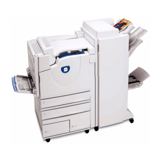
Xerox Phaser 7760 Service Manual
Color laser printer
Hide thumbs
Also See for Phaser 7760:
- Service manual (564 pages) ,
- User manual (158 pages) ,
- Advanced features manual (105 pages)
Advertisement
Advertisement
Table of Contents

Related Manuals for Xerox Phaser 7760


Summary of Contents for Xerox Phaser 7760
- Page 1 Phaser® 7760 Color Laser Printer Service Manual 705P01119 March 2006...
- Page 2 Service Safety Summary....................viii Electrostatic Discharge (ESD) Precautions..............Symbology and Nomenclature ..................Regulatory Specifications....................Phaser 7760 Printer Introduction and Overview ............. xiii Phaser 7760 Printer Configurations ................xiii Parts of the Printer ......................Phaser 7760 Control Panel Configuration............... Image Processor Board and Rear Panel Host Interface ..........
-
Page 3: Service Call Procedures
1 Service Call Procedures Service Call Procedures....................Detailed Maintenance Activities (High Frequency Service Items - HFSI) ....... Cleaning Procedures....................... Cleaning Materials ......................Common Tools ........................ Launch Service Call Procedures March 2006 Phaser® 7760 Color Laser Printer... - Page 4 2 Chain 1 04.350 Printer Video Failure.................... 2-38 04.351 Printer Xerographics Failure................2-39 01.300, 01-516 Left Cover (Door A) Open ..............04.352, 04.354, 04.358 Printer Communications Failure ..........2-39 01.301, 01-511 Left Lower Cover (Door B) Open ............04.353 Printer Paper Handling Failure ................2-40 01.302, 01-510 Front Cover Door Open .................
- Page 5 07.954, 01-540.05 Tray 1 (MPT) Size Mismatch (Slow Scan Direction) ......2-87 09.432 Yellow Imaging Unit Replaced ................2-141 07.959, 07-513, 07-517 Tray 1 Paper Mismatch 1............2-88 09.433 Magenta Imaging Unit Replaced ................. 2-142 07.960, 1-540.05 Tray 1 (MPT) Paper Mismatch 2............2-88 09.434 Cyan Imaging Unit Replaced................
- Page 6 2 Chain 12 A/P Finisher 12-296, 12-576, 12-577 Stapler Move Position Sensor Off Fail........2-295 12-300, 12-560 Eject Cover Open................... 2-298 12-112, 12-576, 12-577 H-Transport Entrance Sensor On Jam ........2-187 12-302, 12-564 Finisher Front Door Interlock OPEN (A/P Finisher) ....... 2-299 12-113 Booklet In Sensor On Jam ..................
-
Page 7: Image Quality
3 Image Quality Print-Quality Problems Overview ..................Control Panel Test Prints ....................Engine Test Prints......................Initial Actions Before Troubleshooting................Launch Image Quality March 2006 Phaser® 7760 Color Laser Printer... - Page 8 Figure 1 Booklet Knife Status Indicator RAPs Launch March 2006 12-261, 12-518 Booklet Knife Folding Sensor Fail 2-266 Phaser® 7760 Color Laser Printer...
- Page 9 REP 12.64 Finisher Buffer Roll ..................4-80 REP 12.65 Finisher Bottom Buffer Chute Assembly............4-82 REP 12.66 Finisher H-Transport Drive Belt ..............4-83 REP 12.67 Finisher Eject Chute Assembly ..............4-84 REP 12.68 Finisher PWB ....................4-86 REP 12.69 Gear Replacement..................4-87 4 Covers REP 14.1 Top Cover .......................
- Page 10 5 Overview PL 10.2 Top Covers and Inner Covers................5-35 PL 10.3 Rear Cover......................5-36 Introduction ........................Subsystem Information ....................Inverter Parts Lists PL 11.1 Inverter Transport ....................5-37 Duplex Transport Drives PL 12.1 Duplex Transport Assembly: 1 of 2..............5-38 PL 1.1 Drive Unit ......................
- Page 11 PL 21.17 Booklet Component -2 (End Guide)..............5-76 PL 21.18 Booklet Component -3 ..................5-77 PL 21.19 Booklet Component -4 ..................5-78 PL 21.20 Booklet Component -5 ..................5-79 PL 21.21 Booklet Component -6 (Chute) ................ 5-80 PL 21.22 Booklet Component -7 ..................5-81 PL 21.23 Booklet Tray Component .................
- Page 12 6 Control Panel Diagnostics Introduction ........................Diagnostic Fault History ....................Control Panel Diagnostics....................Control Panel Troubleshooting..................6-18 Inoperable Printer......................6-19 Power Supplies and Interlocks..................6-19 Media Jams and the Paper Path..................6-22 Operating System and Application Problems..............6-23 6 Diagnostics Procedures Date and Time.........................
- Page 13 7 Printer Plug/Jack Locations Printer Plug/Jack Locations..................... 7 Finisher Plug/Jack Locations Finisher Plug/Jack Locations ..................7-39 7 Wirenets AC Wirenets ........................7-53 +3.3 VDC / +3.3 VDC Wirenets..................7-55 +5 VDC Wirenets ......................7-57 +5 VDC RTN Wirenets ....................7-61 +24 VDC Wirenets ......................
-
Page 14: Theory Of Operation
8 Theory of Operation Phaser 7760 Print Process ..................... Operational Overview...................... EAHG Toner........................8-11 Technology Overview...................... 8-11 ROS and Regicon Technology Overview................ 8-13 RegiCon Overview ......................8-15 Sensors ........................... 8-17 Advanced Finisher ......................8-21 Professional Finisher....................... 8-35 Launch Theory of Operation March 2006 Phaser®... - Page 15 1. Send the Image Unit ID postscript snippet to the printer. a. This snippet can be downloaded from: http://www.office.xerox.com/ 1 of 1 Copyright © 2004 Xerox Corporation. All rights reserved. XEROX®, the stylized X®, and Phaser® trademarks of Xerox Corporation in the United States and/or other countries.
Need help?
Do you have a question about the Phaser 7760 and is the answer not in the manual?
Questions and answers