
Related Manuals for Siemens SICHARGE 8EM4110 Series


Summary of Contents for Siemens SICHARGE 8EM4110 Series
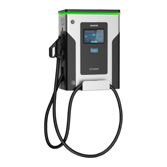
- Page 1 Edition 07/2023 OPERATING INSTRUCTIONS SICHARGE SICHARGE UC Dispenser 8EM4110-XXXXX-XXXX support.industry.siemens.com...
- Page 2 Introduction Safety instructions SICHARGE UC Description Dispenser Application planning Operating Instructions Installation Connecting Commissioning Operation Handling alarms and errors Maintenance and service Disposal Service & Support Technical specifications Declaration of Conformity List of abbreviations 07/2023 A5E52329862-AB Continued on next page...
- Page 3 Continued Checklists Repair Dispenser Operating Instructions...
- Page 4 Note the following: WARNING Siemens products may only be used for the applications described in the catalog and in the relevant technical documentation. If products and components from other manufacturers are used, these must be recommended or approved by Siemens. Proper transport, storage, installation, assembly, commissioning, operation and maintenance are required to ensure that the products operate safely and without any problems.
-
Page 5: Table Of Contents
Electromagnetic fields....................... 18 Safety sign........................19 Identification of the device....................20 DC shutdown........................21 2.9.1 DC shutdown button......................21 2.9.2 DC shutdown loop......................22 2.9.3 Integration of an external button..................22 2.10 Cybersecurity at Siemens....................23 Dispenser Operating Instructions, 07/2023, A5E52329862-AB... - Page 6 Table of contents Description............................24 Product overview......................24 Overview of device versions....................25 Equipment variants......................26 Display and operator controls.................... 27 3.4.1 Display and operator controls.................... 27 3.4.2 Internal design........................30 Charging cable Combo 2....................32 Electrical protection devices....................33 Application planning..........................
- Page 7 Cleaning the touch screen....................96 10.3.2 Cleaning the cabinet and the charging cable..............97 Disposal.............................. 11.1 Disposing of packaging..................... 99 11.2 Disposal of the Dispenser....................99 Service & Support..........................100 12.1 Siemens Industry Support....................100 Dispenser Operating Instructions, 07/2023, A5E52329862-AB...
- Page 8 Table of contents Technical specifications........................102 13.1 Technical specifications....................102 13.2 Charging current/power curve................... 104 Declaration of Conformity........................105 List of abbreviations........................... 106 Checklists............................107 Checklist for preparations for use..................107 Installation checklist......................107 Commissioning checklist....................107 Preventive maintenance checklist..................107 Repair..............................
-
Page 9: Introduction
Introduction About the operating instructions The operating instructions contain the information for the safe operation and intended use of the SICHARGE UC Dispenser. Safekeeping the operating instructions The operating instructions are an integral part of the product and an indispensable part of the product safety concept. -
Page 10: Basic Information
Introduction 1.2 Basic information Basic information The Dispenser meets all required technical standards and therefore provides the greatest possible product safety. To guarantee the safety of all persons, installations and equipment, observe the following safety instructions. Guidelines and regulations In order to ensure comprehensive safety, adhere to the following guidelines and regulations: •... -
Page 11: Open-Source Software
Siemens accepts no liability for the use of the open source software over and above the intended program sequence, or for any faults caused by modifications to the software. -
Page 12: Safety Instructions
Safety instructions Structure of safety instructions section The safety instructions section describes the intended use by the target groups and potential dangers. General 2.2.1 Guidelines and regulations The Dispenser meets all required technical safety standards and therefore provides the greatest possible product safety. In order to ensure comprehensive safety, adhere to the following guidelines and regulations: •... -
Page 13: Qualified Personnel
Alterations to the device The operating instructions describe permissible changes to the Dispenser. Other modifications that are not part of this or any other official document of Siemens are not permitted. This applies to both electrical modifications (connecting, disconnecting or swapping connections of electrical devices, etc.) and mechanical modifications (e.g. -
Page 14: Hazards During Transport, Mounting, Operation And Maintenance
Safety instructions 2.3 Hazards during transport, mounting, operation and maintenance Hazards during transport, mounting, operation and maintenance 2.3.1 Personal protective equipment (PPE) Personal protective equipment protects you against hazards to your health and safety. Use your personal protective equipment in accordance with occupational safety guidelines and accident prevention regulations. -
Page 15: Falling Parts
Safety instructions 2.3 Hazards during transport, mounting, operation and maintenance 2.3.5 Falling parts When working at an elevated height, watch out for falling parts, cables or plugs. 2.3.6 Work areas Tripping and slipping hazards Keep work areas clean and tidy to prevent tripping and slipping. Accident hazards Avoid accidents, personal injury and damage to vehicles and the Dispenser. -
Page 16: Risk Of Crushing Or Cuts
Safety instructions 2.5 Dangers due to electric current 2.3.7 Risk of crushing or cuts When mounting, look out for moving parts and protruding cables and bolts. Hazards in the event of fire, explosions and emergencies Fire and explosion protection Do not store or use highly flammable liquids that produce flammable vapors, such as gasoline or ethanol, in the proximity of the Dispenser. -
Page 17: Damaged Parts
Safety instructions 2.5 Dangers due to electric current 2.5.2 Damaged parts Only use undamaged devices and parts. Improper handling can result in damage to the equipment. Hazardous voltages may be present on the cabinet or exposed components if devices are damaged. Dangerous voltages can result in severe injuries or death. -
Page 18: Electric Shock Due To Lack Of Earthing
Safety instructions 2.6 Dangers from electric fields 2.5.4 Electric shock due to lack of earthing If the protective conductor connection is missing or incorrectly connected, high voltages may be present on exposed parts. Touching the parts can lead to severe injuries or death. Connect the protective conductor properly to ground the Dispenser. -
Page 19: Safety Sign
Safety instructions 2.7 Safety sign Safety sign Safety signs are attached to the Dispenser and on the packaging for safe handling of the Dispenser. Safety signs on the packaging The following safety signs are attached to the packaging of the Dispenser: Safety sign Meaning Marking of the center of gravity... -
Page 20: Identification Of The Device
Safety instructions 2.8 Identification of the device Identification of the device The nameplate uniquely identifies the Dispenser. The nameplate also contains the identification data of the device, the manufacturer and the CE marking. Information on the nameplate You can find the following information on the Dispenser nameplate: Figure 2-1 Example of the nameplate, 1 charging point Figure 2-2 Example of the nameplate, 2 charging points Nameplate positions... -
Page 21: Dc Shutdown
Safety instructions 2.9 DC shutdown DC shutdown 2.9.1 DC shutdown button In a dangerous situation, pressing the DC shutdown button immediately puts the charging station into a safe state. Position of the button The DC shutdown button is positioned on the front of the charging station in the middle of the device door. -
Page 22: Dc Shutdown Loop
Safety instructions 2.9 DC shutdown Revoke the DC shutdown state again NOTE Eliminate the hazardous situation First eliminate the hazardous situation. Only then cancel the DC shutdown state. The DC shutdown button is equipped with a rotary release. An arrow on the top of the button indicates the direction of rotation for unlatching. -
Page 23: Cybersecurity At Siemens
Siemens’ products and solutions undergo continuous development to make them more secure. Siemens strongly recommends that product updates are applied as soon as they are available and that the latest product versions are used. Using versions that are obsolete or are no longer supported can increase the risk of cyber threats. -
Page 24: Description
• Similar electric vehicles You can connect up to 4 charging points to a charging station using multiple Dispenser via a daisy chain. The SIEMENS charge controller ensures that the connected vehicles are charged one after the other in the specified sequence. -
Page 25: Overview Of Device Versions
Description 3.2 Overview of device versions Overview of device versions The following table shows the device designs of the 3 mounting variants. Section "Equipment variants (Page 26)" contains a table of the different options you can choose. Table 3-1 Overview of device versions Floor mounting Wall mounting Ceiling mounting... -
Page 26: Equipment Variants
Description 3.3 Equipment variants Equipment variants The following components are optionally available depending on the device version: • Touch screen (HMI) • RFID card reader for user authentication (OCCP 1.6J based) The following table shows the various selection and equipment options. Figure 3-1 Dispenser article number structure Dispenser Operating Instructions, 07/2023, A5E52329862-AB... -
Page 27: Display And Operator Controls
Description 3.4 Display and operator controls Display and operator controls 3.4.1 Display and operator controls Display and operator controls Generation 2 This figure shows the external structure, display and operator controls of the Dispenser Generation 2. For this example, the device version with the options HMI, RFID and two charging points was selected. - Page 28 Description 3.4 Display and operator controls A cable holder for the second charging cable is mounted on the rear. ① Cable holder for second charging cable ② Mounting bar for wall and ceiling mounting Figure 3-3 Structure rear view Generation 2 LED display The Dispenser is equipped with an LED display for each charging point.
- Page 29 Description 3.4 Display and operator controls Touch screen (HMI) The Dispenser can be equipped with a central touch screen (HMI) in 10" format. The optional HMI has a touch screen in widescreen format. Due to the large viewing angle of the HMI, it is easier to recognize operating information from different viewing directions.
-
Page 30: Internal Design
Miniature circuit breakers ⑨ DC fuses ④ Ethernet switch ⑩ LED display ⑤ Thermostat ⑪ Siemens controller ⑥ Industrial power supply unit 230 V AC / 48 V ⑫ RFID reader = Option Figure 3-4 Internal design, 1 charging point Dispenser Operating Instructions, 07/2023, A5E52329862-AB... - Page 31 Miniature circuit breakers ⑨ DC fuses ④ Ethernet switch ⑩ LED display ⑤ Thermostat ⑪ Siemens controller ⑥ Industrial power supply unit 230 V AC / 48 V ⑫ RFID reader = Option Figure 3-5 Internal design, 2 charging points Dispenser Operating Instructions, 07/2023, A5E52329862-AB...
-
Page 32: Charging Cable Combo 2
Description 3.5 Charging cable Combo 2 Charging cable Combo 2 The Dispenser is equipped with a charging cable for charging electric vehicles with direct current. The charging cable enables charging of electric vehicles with a CCS Combo 2 charging socket according to the standard IEC 62196-3. Charging contacts To safely transmit the high charging power, the Combo 2 connector of the charging cable uses the following charging contacts:... -
Page 33: Electrical Protection Devices
Description 3.6 Electrical protection devices Temperature monitoring The integrated temperature monitoring of the charging cable ensures safe transfer of the charging power. Temperature sensors monitor the charging contacts DC+ and DC- during the entire charging process. When the temperature at one of the charging contacts exceeds 90 °C, the charge controller immediately switches off the power supply of the charging cable. - Page 34 Description 3.6 Electrical protection devices Overload protection The charging station constantly monitors the input current and the output current. If a measured current exceeds the limit values during a charging process, the charging station stops the charging process. The output contactors of the Dispenser are opened so that no current flows to the vehicle.
-
Page 35: Application Planning
Disclaimer of liability Customers are responsible for safekeeping of the documents and objects received. Siemens is not obligated to reproduce transferred documents and objects. Siemens is not liable for the improper use of intelligent devices, such as RFID cards and readers. Dispenser... -
Page 36: Checking The Transport Packaging
Application planning 4.1 Checking incoming goods 4.1.2 Checking the transport packaging Start the inspection of the transport packaging with a visual inspection of the shock indicator. Checking the shock indicator During transport, a transport pallet with shock absorbers protects the Dispenser against shocks and vibrations. -
Page 37: Unpacking The Dispenser
Application planning 4.1 Checking incoming goods 4.1.3 Unpacking the dispenser 4.1.3.1 Unpacking the Dispenser for floor installation Depending on the transport route, the carrier supplies the Dispenser for floor mounting in different transport packaging. Specifications for the disposal of the packaging material can be found in the section Disposal (Page 99). -
Page 38: Unpacking The Dispenser For Wall Or Ceiling Mounting
Application planning 4.1 Checking incoming goods 4.1.3.2 Unpacking the Dispenser for wall or ceiling mounting The Dispenser for wall or ceiling installation is included in the same transport packaging irrespective of the transport path. Specifications for the disposal of the packaging material can be found in the section Disposal (Page 99). -
Page 39: Location Planning
Application planning 4.2 Location planning Location planning 4.2.1 Selection criteria for a safe location For safe operation of the Dispenser you need a location that meets the following requirements. NOTICE Accident hazards Avoid accidents, personal injury and damage to vehicles and the Dispenser. These are, for example, inattentiveness, slipping and tripping risks as well as vandalism. -
Page 40: Properties Of The Mounting Surface
Application planning 4.2 Location planning 4.2.2 Properties of the mounting surface • Floor mounting: To ensure the stability of the Dispenser, the base must meet the following requirements: – Level – Dry – Sufficiently solid and capable of bearing the load (e.g. concrete area in quality class C30/37) NOTE Sealing the mounting plate... -
Page 41: Minimum Clearances
Application planning 4.2 Location planning 4.2.3 Minimum clearances Minimum clearances for floor mounting For operation and maintenance and to ensure proper ventilation of the Dispenser, you must maintain the following minimum clearances (in mm). The following figure shows the minimum distances for floor mounting in the top view with 1 charging point. ①... - Page 42 Application planning 4.2 Location planning The following figure shows the minimum distances for floor mounting in the top view with 2 charging points. Figure 4-3 Minimum distances for floor mounting top view 2 charging points Dispenser Operating Instructions, 07/2023, A5E52329862-AB...
- Page 43 Application planning 4.2 Location planning The following figure shows the minimum distances for floor mounting in the front view. Figure 4-4 Minimum clearances for floor mounting front view Dispenser Operating Instructions, 07/2023, A5E52329862-AB...
- Page 44 Application planning 4.2 Location planning Minimum clearances for wall/ceiling mounting For operation and maintenance and to ensure proper ventilation of the Dispenser, you must maintain the following minimum clearances (in mm). The following figure shows the minimum clearances for wall/ceiling mounting in the top view. ①...
-
Page 45: Maximum Permissible Temperature
Application planning 4.2 Location planning The following figure shows the minimum clearances for wall/ceiling mounting in the front view. Figure 4-6 Minimum clearances for wall/ceiling mounting front view 4.2.4 Maximum permissible temperature The dispenser is designed for operation at a maximum ambient temperature of +45 °C. A temperature sensor monitors the internal temperature of the dispenser. -
Page 46: Electrical Installation
Application planning 4.2 Location planning 4.2.5 Electrical installation • Low voltage: The Dispenser is designed for the connection to the low-voltage network (230 V AC) via the charging station. Connect the Dispenser to the SICHARGE UC charging station using a properly dimensioned supply cable. •... -
Page 47: Bumper
Application planning 4.2 Location planning 4.2.6 Bumper ① To protect the Dispenser from the impact of other vehicles, install a bumper ① Bumper ② Vehicle ③ Dispenser Figure 4-7 Example: Correct position of bumper and Dispenser Plan for bumpers based on the dimensions of the vehicles used. The bumper must stop the vehicle before the vehicle overhang touches the Dispenser. -
Page 48: Geometry Of The Infrastructure
Application planning 4.3 Geometry of the infrastructure Geometry of the infrastructure You can design the location for charging electric vehicles in different ways. This section provides information about the placement of the Dispenser. In the examples the parking spaces and the different vehicle inlets for the charging cable are displayed. ①... - Page 49 Application planning 4.3 Geometry of the infrastructure Space required for the Dispenser The dispenser requires a minimum distance of 1.6 m x 1.8 m (W x D). Follow the instructions in this section: Minimum clearances (Page 41) The DC charging cable of the Dispenser is available in lengths of 3.5 m, 6 m and 10 m. Depending on the cable length, examples of the parking geometry are shown in the following figure: ①...
-
Page 50: Preparing The Mounting Surface
Application planning 4.4 Preparing the mounting surface Preparing the mounting surface 4.4.1 Preparation for floor mounting To securely fasten the Dispenser to the intended mounting surface on the ground, you must prepare the mounting surface. CAUTION Secure work area Ensure a sufficiently large safety zone around the mounting surface. For example, use warning signs and barriers. - Page 51 Application planning 4.4 Preparing the mounting surface Cable routing The figure shows the cables from the charging station to the dispenser. The cables are inserted in the foundation through the supporting foot from below into the dispenser. ① AC-AUX cable ④...
- Page 52 Application planning 4.4 Preparing the mounting surface Drill holes for fixing points on the floor To fasten the Dispenser, the following drill holes must be available for the fixing points: Figure 4-12 Fixing points of the mounting plate Fixing to the floor The mounting material is not included in the scope of delivery.
-
Page 53: Preparation For Wall/Ceiling Mounting
Application planning 4.4 Preparing the mounting surface 4.4.2 Preparation for wall/ceiling mounting To securely fasten the Dispenser to the intended mounting surface, you must prepare the mounting surface. CAUTION Secure work area Ensure a sufficiently large safety zone around the mounting surface. For example, use warning signs and barriers. - Page 54 Application planning 4.4 Preparing the mounting surface Cable lengths The following table shows the cable lengths from the screw connections up to the terminals in the Dispenser. Table 4-2 Min. cable lengths Dispenser wall / ceiling installation Description Min. cable length in the Dispenser 230 V AC AUX supply L/N/PE 0.7 m...
-
Page 55: Storing The Dispenser
• Check every 6 months that actual storage conditions do not allow condensation to form. • Check the Dispenser for damage every 6 months. • Check the buffer battery of the Siemens controller every 6 months at a storage temperature of ≈ 70 °C. Replace the backup battery if necessary. -
Page 56: Transporting The Dispenser
Application planning 4.6 Transporting the Dispenser Transporting the Dispenser WARNING Danger to life when standing under lifted loads If hoisting gear or load handling equipment fail, a lifted load can drop. If you are in the hazardous area under or next to the lifted load at this time, death, serious injury and material damage may result. - Page 57 Application planning 4.6 Transporting the Dispenser Transporting the Dispenser for floor mounting with lifting equipment The Dispenser floor mounting is delivered with two transport plates for mounting. 1. Connect the transport plates of the Dispenser and the lifting equipment. Only use suitable and approved lifting equipment.
- Page 58 Application planning 4.6 Transporting the Dispenser Transporting the Dispenser for wall/ceiling mounting with lifting equipment The Dispenser wall/ceiling mounting is delivered with mounting rails on the rear of the device. Figure 4-16 Attachment points and the lifting equipment 1. Mount the shackle into the holes on the right and left of the mounting rail 2.
-
Page 59: Installation
Installation Floor mounting 5.1.1 Mounting the Dispenser on the floor Due to the variety of options, the total weight of the Dispenser is different, depending on the equipment. To mount the Dispenser at the location, you must lift the Dispenser off the transport pallet. If the Dispenser is heavy, transport it to the prepared mounting surface using a forklift. -
Page 60: Wall/Ceiling Mounting
Installation 5.2 Wall/ceiling mounting 8. Tighten the nuts with the tightening torque of the bolt anchors as per the manufacturer's instructions. 9. Seal the openings from the mounting surface to the mounting plate with a suitable sealant to prevent the ingress of moisture, animals and insects. 10. - Page 61 Installation 5.2 Wall/ceiling mounting Mounting the SICHARGE UC Dispenser To position the Dispenser on the mounting surface, follow these steps: 1. Position the Dispenser on the mounting surface using the bottom bolt anchor 2. Check whether the alignment of the Dispenser above the bottom bolt anchor of the mounting surface is correct 3.
-
Page 62: Connecting
Connecting Cable for connecting the auxiliary power supply To connect the Dispenser to the charging station, connect the auxiliary power supply cable to the terminal strip -XD01 of the Dispenser. Requirements • You have opened the cabinet. • You have inserted the auxiliary power supply cable into the enclosure. Cable length and cable routing A table with the minimum cable lengths in the Dispenser and schematic cable routing is available in section Preparing the mounting surface (Page 50). - Page 63 Connecting 6.1 Cable for connecting the auxiliary power supply Connections of the power supply cable The figure below shows the connection of the power supply cable. ① Version with 1 charging point ④ N terminal ② Version with 2 charging points ⑤...
-
Page 64: Connecting The Dc Cables
Connecting 6.2 Connecting the DC cables Connection of additional Dispenser To connect additional Dispenser to the same charging station, the auxiliary power supply is ⑥ looped through. This is shown as item in the "Auxiliary power supply connection" figure. Follow the procedure described above to connect the cable for the auxiliary power supply. Connecting the DC cables To connect the Dispenser to the charging station, connect the DC cable to the DC connectors of the Dispenser. - Page 65 Connecting 6.2 Connecting the DC cables Connections for the DC cables The following picture shows the connection of the DC cables. ① Version with 1 charging point ④ DC- conductor ② Version with 2 charging points ⑤ Protective conductor ③ DC+ conductor ⑥...
-
Page 66: Connecting The Communication Cable
Connecting 6.3 Connecting the communication cable Connecting DC+ and DC- conductors Connect the DC+/DC- conductors to the DC busbars: To connect a DC conductor, proceed as follows: 1. Remove the sheath of the cable to connect the cable lug. 2. Select an M10-size cable lug for the corresponding conductor cross-section. 3. - Page 67 Connecting 6.3 Connecting the communication cable Ethernet connection The following figure shows the connection of the Ethernet cable. ① Version with 1 charging point ③ Ethernet cable ② Version with 2 charging points ④ Loop through for daisy chain Figure 6-3 Ethernet connection Dispenser Operating Instructions, 07/2023, A5E52329862-AB...
- Page 68 Connecting 6.3 Connecting the communication cable Connecting the Ethernet cable NOTICE Network connection The SICHARGE UC devices form a closed network. Do not establish a connection to other networks and devices. Observe the specifications for the routing of Ethernet cables in the section Selection criteria for a safe location (Page 39).
-
Page 69: Connection Table
Connecting 6.4 Connection table Connection of additional Dispensers The Ethernet connection is looped through to connect additional Dispensers to the same ④ charging station. This is shown as item in the " Ethernet connection" figure. To do this, perform the sequence shown above to connect the Ethernet cable. Connection table The following table provides an overview of the Dispenser terminals. -
Page 70: Commissioning
The Initial commissioning section provides an overview of the activities to be performed during initial commissioning. The following persons may perform these activities: • Service technicians from Siemens • Persons trained and authorized by Siemens Optical check Take photos of the installation for the commissioning report. We recommend taking pictures of the front and side view of each installed device (charging stations, Dispenser, MastHood, MastPanto). - Page 71 Commissioning 7.1 Initial commissioning Check of the electrical functionality The service technician checks the following components and functions during initial commissioning: • DC shutdown switch – Press the DC shutdown switch – Alarm message on HMI indicates DC shutdown switch actuation –...
-
Page 72: Commissioning Checklist
Commissioning 7.3 Setting the thermostat Commissioning checklist The checklist for commissioning is available on the Internet here: Installation and Commis sioning Checklist (https://support.industry.siemens.com/cs/ww/en/view/109815372) Setting the thermostat Set the thermostat in the dispenser correctly to prevent condensation. NOTE The thermostat setting at delivery is 0 °C The thermostat is set to 0 °C at delivery. -
Page 73: Operation
Operation Introduction For easier operation you can equip the Dispenser with an HMI to display a user interface. Alternatively, Dispenser and charging station are also available as equipment variant without HMI. In this variant, the main source of the status is the LED indicator. Operation without HMI When using the equipment variant without HMI, the status of the charging point is displayed via LEDs. -
Page 74: Operation Via Hmi
Operation 8.3 Operation via HMI 4. The charging plug is locked. The charging point flashes green. The connection/handshake is being established. 5. When the LED flashes blue, the vehicle is being charged. The flashing frequency indicates the battery charge status, with constant blue light meaning 100%. 6. -
Page 75: Terminating The Charging Process
Operation 8.3 Operation via HMI 8.3.2 Terminating the charging process The charging process can be ended automatically or manually. Automatic termination The following scenarios result in automatic termination of the charging process: • Vehicle ends charging process • Vehicle detects a fault •... -
Page 76: Hmi Functions
The time is factory set to the UTC time zone. When the charging station is connected to the Internet, the time is synchronized. Information on how to set the time manually can be obtained from your Siemens partner. • Settings To go to the general settings (Page 84), press this display element. - Page 77 Operation 8.3 Operation via HMI Select a charging point to obtain detailed information. Figure 8-2 Selecting a charging point Dispenser Operating Instructions, 07/2023, A5E52329862-AB...
-
Page 78: Authentication Screen
Operation 8.3 Operation via HMI 8.3.3.3 Authentication screen These screens guide you through the authentication process. If an authentication is required, an authentication screen is displayed when a charging point is selected. The charging station offers RFID, PIN or both as authentication options. RFID &... - Page 79 Operation 8.3 Operation via HMI RFID If you selected the RFID authentication method, the following image is displayed: Figure 8-4 RFID If you have selected the authentication method PIN, the following screen is displayed: Figure 8-5 PIN Dispenser Operating Instructions, 07/2023, A5E52329862-AB...
-
Page 80: Establishing A Connection
Operation 8.3 Operation via HMI 8.3.3.4 Establishing a connection The Dispenser establishes a connection to the electric vehicle before the charging transaction and performs a so-called handshake. The handshake ensures that the Dispenser is compatible with the vehicle and all safety requirements are fulfilled. This process may take up to a minute. -
Page 81: Charging Screen
Operation 8.3 Operation via HMI 8.3.3.5 Charging screen During an active charging process the HMI displays all the relevant information on the vehicle status and the charging station status. The following is displayed on this screen: • Charge status of the vehicle •... -
Page 82: Out Of Order
Operation 8.3 Operation via HMI 8.3.3.6 Out of order If charging at all the connected charging points of the charging station is not possible due to an error, the charging station goes out of order. The HMI displays that the charging station is currently out of order. -
Page 83: Settings
Operation 8.3 Operation via HMI 8.3.4 Settings 8.3.4.1 Select language You can change the language of the user interface using the language selection screen. Procedure To change the language, follow these steps: 1. Press the icon in the menu bar. The current language is displayed next to the icon. The language selection screen opens. -
Page 84: Settings Menu
Operation 8.3 Operation via HMI 8.3.4.2 Settings menu In the Settings menu you can view information on the system and retrieve detailed information on the following fields: • Last charging report (Page 85) • Alert log (Page 86) • Advanced mode (Page 87) General system overview To open the screen settings, press on the icon. -
Page 85: Last Charging Report
Operation 8.3 Operation via HMI 8.3.4.3 Last charging report Information on the last charging process for each dispenser is displayed in the area "Last charging report". To open the charging report, select the "Last report" in the Settings (Page 84). There may be several charging points connected to a charging station without their own user interface. -
Page 86: Alert Log
Operation 8.3 Operation via HMI 8.3.4.4 Alert log The last alerts are displayed in the "Alert log" area. To open the Alert log, select the "Alert log" button in the Settings (Page 84). Figure 8-12 Alert log The following information is displayed: •... -
Page 87: Advanced Mode
Operation 8.3 Operation via HMI 8.3.4.5 Advanced mode Requirement You have authenticated yourself by entering a PIN. Advanced settings Information and setting options for each charging port are shown in the area "Advanced settings". To open the area, select the "Advanced settings" button in the Settings (Page 84). Figure 8-13 Advanced settings If there are several dispensers, select the one you require using the drop-down menu. -
Page 88: Connecting The Charging Cable
Operation 8.3 Operation via HMI Table 8-2 Information about temperature Section Temperature Speed Fan control system Temperature at the fan control Fan speed in % of the maximum speed To change the maximum fan speed, press the text box and enter a value using the numeric keypad. - Page 89 Operation 8.3 Operation via HMI Figure 8-14 Connecting the charging cable The charging plug is locked and the vehicle and charging station set up a connection. Communication setup may take up to 60 seconds. If communication has not been successfully established after 60 seconds, remove the charging cable and restart the process. Dispenser Operating Instructions, 07/2023, A5E52329862-AB...
-
Page 90: Handling Alarms And Errors
Handling alarms and errors Overview In case of an error, the Dispenser and the charging station automatically conducts an error diagnostics. The Dispenser and the charging station issue different alarm messages depending on the type of error. A list of all messages and how to correct the error can be found under "Alarm messages in the alarm history (Page 91)". -
Page 91: Alarm Messages In The Alarm History
• Alarm message Alarm messages and error handling In the "Alarm history" menu, the charging station lists the following alarm messages: NOTE You can find detailed information in the Software Manual (https://support.industry.siemens.com/cs/ww/en/view/109817021). Table 9-1 Alarm messages and error handling Alarm message Description outputEnabledTimeout... - Page 92 Handling alarms and errors 9.2 Alarm messages in the alarm history Alarm message Description IllegalTransition Illegal transition of EVSEcore state mainProcessError Error at main processor fiber, most likely an unexpected sequence of AKKA stages cpStateFault Unexpected transition of CP state from C/D to A noCommunicationToAkka Communication with AKKA was not established (configurable timeout)
- Page 93 Handling alarms and errors 9.2 Alarm messages in the alarm history Alarm message Description noCommunicationToGreenInvert No communication established with GreenInvert (configurable timeout) communicationLostGreenInvert Loss of communication with GreenInvert (configurable timeout) inputBreakerFail Unexpected state of the input circuit breaker received outputBreakerFail Unexpected state of the output circuit breaker received dcOverVoltage DC voltage value too high for the specific hardware...
- Page 94 Handling alarms and errors 9.2 Alarm messages in the alarm history Alarm message Description acUnderVoltageL1 AC voltage value too low for the specific hardware (only set when converter ON) acUnderVoltageL2 AC voltage value too low for the specific hardware (only set when converter ON) acUnderVoltageL3 AC voltage value too low for the specific hardware (only set...
-
Page 95: Maintenance And Service
Maintenance and service 10.1 Safety instructions To guarantee the safety of persons and equipment during maintenance and service of the Dispenser, observe the following safety instructions. WARNING Electric shock from live parts Electrical systems have live parts during operation. If the system has not been disconnected from the power supply before maintenance work is performed inside the station, death, serious injury or damage to property may occur. -
Page 96: Maintenance Plan
After the first year, carry out the checks every 12 months or at shorter intervals if necessary due to the ambient conditions (e.g. high dust exposure). Check Dispenser Follow the steps outlined in the checklist in the following document "Preventive Maintenance Checklist (https://support.industry.siemens.com/cs/ww/en/view/109815371)". 10.3 Conduct maintenance on Dispenser 10.3.1 Cleaning the touch screen The touch screen is designed for low-maintenance operation. -
Page 97: Cleaning The Cabinet And The Charging Cable
Maintenance and service 10.3 Conduct maintenance on Dispenser NOTE Only clean the touch screen when it is switched off If you clean the touch screen when it is switched on, you can trigger operator errors. This may put the Dispenser unintentionally into an undesirable operating state. •... - Page 98 Maintenance and service 10.3 Conduct maintenance on Dispenser Cleaning the exterior surfaces of the cabinet • Wipe down the exterior surfaces of the Dispenser with a damp cloth. • Then rub the Dispenser dry. • Do not scrape off stubborn dirt using hard objects. •...
-
Page 99: Disposal
Disposal 11.1 Disposing of packaging Environmental protection and the conservation of its resources are of high priority for our corporate goals. Global environmental management according to ISO 14001 ensures adherence to laws and sets high standards for this. Environmentally friendly design, technical safety and health protection are solid targets even during the development of our products. -
Page 100: Service & Support
Service & Support 12.1 Siemens Industry Support Technical questions If you have technical questions, contact the Customer Support Center. Have the following information at hand when you call: • Type of Dispenser • Serial number You can find this information on the nameplate of the Dispenser. - Page 101 Service & Support 12.1 Siemens Industry Support Country Hotline number Language Type of number Portugal +35 1308810971 Portuguese National Spain +34 951370049 Spanish Geographic (Málaga) Sweden +46 20881302 Swedish Toll-free Switzerland +41 800003278 German/French/Itali Toll-free United Kingdom +44 2045383569 English...
-
Page 102: Technical Specifications
Technical specifications 13.1 Technical specifications Technical specifications Supply voltage input Voltage 230 V AC (1 ∼ + PE) ± 10% Frequency 50 Hz DC output Generation 2 Rated power 0 ... 150 kW Current (max.) 0 ... 250 A Voltage (range) 0 ... 1000 VDC Intrinsic energy consumption at 230 V Basic version in standby 32 W Basic version during charging 41 W... - Page 103 16 ... 28 mm Cable diameter PE single wire 13 ... 21 mm Cable diameter AC conductor 9 ... 17 mm Ethernet cable diameter 7 ... 8 mm General specifications Charge control system Siemens controller Local user interface Generation 2 10" HMI User login RFID (optional) Network connection Ethernet interface Communication protocol OCPP 1.6 (J‑SON)
-
Page 104: Charging Current/Power Curve
Technical specifications 13.2 Charging current/power curve 13.2 Charging current/power curve The charging current and the power curve depend on the connected charging station. Charging current The following figure shows the progression of the charging current depending on the charging voltage. Figure 13-1 Charging current Power curve The following figure shows the power curve depending on the charging voltage. -
Page 105: Declaration Of Conformity
European Union. Safekeeping location of the declaration of conformity Siemens AG keeps the EU Declaration of Conformity of the SICHARGE UC Dispenser available for the relevant authorities at the following location: Siemens AG... -
Page 106: List Of Abbreviations
List of abbreviations The following abbreviations are used in these instructions: Abbreviation Term Alternating current Auxiliary voltage Controller Area Network Combined Charging System Direct Current OCPP Open Charge Point Protocol Human Machine Interface State of Charge Dispenser Operating Instructions, 07/2023, A5E52329862-AB... -
Page 107: Checklists
Checklists Checklist for preparations for use You can find the checklist for deployment preparation on the Internet here: Installation and Commissioning Checklist (https://support.industry.siemens.com/cs/ww/en/view/109815372) Installation checklist The checklist for installation is available on the Internet here: Installation and Commissioning Checklist (https://support.industry.siemens.com/cs/ww/en/view/109815372) Commissioning checklist The checklist for commissioning is available on the Internet here: Installation and Commis... -
Page 108: Repair
Repair Spare parts You can find a list of spare parts for the Dispenser here on the Internet: Dispenser spare parts (https://support.industry.siemens.com/cs/ww/de/view/109821350) Repair instructions You can find the repair instructions for some spare parts for the Dispenser here on the Internet: Dispenser repair instructions (https://support.industry.siemens.com/cs/ww/de/view/109821353) -
Page 109: Index
Intended use, 12 DC cable, 64 Ethernet cable, 66 Connecting DC cables, 64 Maintenance and service Connecting the auxiliary power supply, 62 Safety instructions, 95 Connecting the Ethernet cable, 66 Cybersecurity at Siemens, 23 Nameplate, 20 Dispenser Operating Instructions, 07/2023, A5E52329862-AB... - Page 110 Index Operation Unpacking Operation without user interface, 73 Dispenser for floor mounting, 37 Terminating the charging process, 75 Dispenser for wall or ceiling mounting, 38 Menu bar, 76 Select language, 83 Settings, 84 Last charging report, 85 Alert log, 86 Advanced mode, 87 Connecting the charging cable, 88 Operator controls, 27...
- Page 111 More information http://www.siemens.com Siemens AG Smart Infrastructure eMobility Siemenspromenade 10 91058 Erlangen, Germany...