
Related Manuals for Siemens VersiCharge 8EM1390 A0 Series


Summary of Contents for Siemens VersiCharge 8EM1390 A0 Series
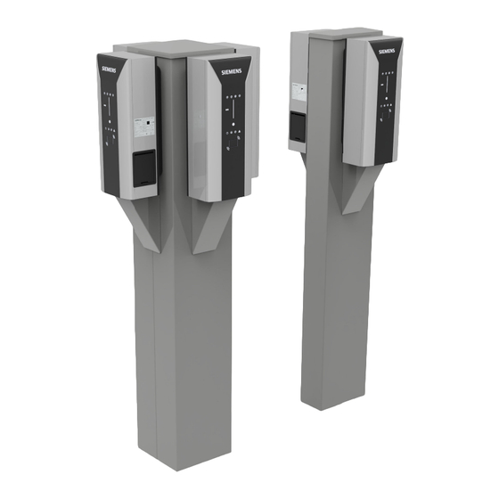
- Page 1 Edition 06/2022 Installation instructions VersiCharge Mounting on column (8EM1390-..A0.) siemens.com/versicharge...
- Page 2 Introduction Safety instructions Description Mounting / Installing / VersiCharge Column Mounting Connecting Hardware Installation Manual Disposal Technical specifications Service Diagrams/Circuitry List of abbreviations 06/2022 A5E51460654-AB...
- Page 3 Note the following: WARNING Siemens products may only be used for the applications described in the catalog and in the relevant technical doc umentation. If products and components from other manufacturers are used, these must be recommended or approved by Siemens. Proper transport, storage, installation, assembly, commissioning, operation and mainten...
-
Page 4: Table Of Contents
Table of contents Introduction............................Purpose of this documentation..................Application........................Qualification for installation....................Safety instructions..........................General safety information....................Safety during setup, installation and maintenance............. 11 Safety during electrical installation..................12 The five safety rules for electrical work................13 Safety during operation....................13 Security information...................... - Page 5 Table of contents Disposal.............................. Disposal..........................37 Technical specifications........................38 Technical specifications....................Service..............................42 Service..........................Diagrams/Circuitry..........................43 List of diagrams/circuitry....................43 Device marking......................... 46 List of abbreviations........................... 47 Abbreviations........................47 Index..............................48 VersiCharge Column Mounting Hardware Installation Manual, 06/2022, A5E51460654-AB...
-
Page 6: Introduction
Introduction Purpose of this documentation These operating instructions contain information for the installation of the VersiCharge AC Wallbox IEC. The operating instructions contain information on the proper use of the Wallbox. The column is approved exclusively for the installation of the VersiCharge Wallbox (article number: 8EM1390-..A0.). -
Page 7: Qualification For Installation
1.3 Qualification for installation Intended use Siemens products may only be used for the applications described in the catalog and the associated technical documentation. If third-party products and components are used, these have to be recommended or approved by Siemens. -
Page 8: Safety Instructions
Safety instructions General safety information This section contains important, generally valid information on: • Avoiding accidents or damage to property • Application planning • Mounting and installation • Operation • Maintenance and cleaning of the charging station • Disposal Read this section carefully and follow the safety regulations. This will minimize safety risks. Make your staff and customers aware of this section. - Page 9 Safety instructions 2.1 General safety information Areas of application of the device • Charging electrically operated vehicles in public and semi-public areas • Charging stations for depots, car parks, public parking areas, and retail • It is not permitted to install the column in hazardous areas where potentially explosive gases and mixtures may form.
- Page 10 Safety instructions 2.1 General safety information Safety equipment To rule out hazardous conditions, it is strictly prohibited to change, remove, bypass, or override safety devices. Failure to follow these instructions may result in hazardous situations that could cause death or serious injury. Risk of explosion and fire Do not store or use flammable liquids that produce flammable fumes, such as gasoline or ethanol, in the vicinity of the charging station.
-
Page 11: Safety During Setup, Installation And Maintenance
Safety instructions 2.2 Safety during setup, installation and maintenance Storage conditions Store the charging station in a clean indoor area. The storage location must meet the following conditions: • Horizontal surfaces • Protection against mechanical stress (e.g. due to shocks, vibrations) •... -
Page 12: Safety During Electrical Installation
Safety instructions 2.3 Safety during electrical installation Electrical cables There is a risk of electric shock due to exposed electrical connections and components. Before starting the installation work, check that the supply cable has been disconnected from the mains and secured against restart. If damage or tampering is visible, do not operate the Wallbox. -
Page 13: The Five Safety Rules For Electrical Work
Safety instructions 2.5 Safety during operation The five safety rules for electrical work The European standard EN 50110‑1 "Operation of electrical installations" prescribes safety rules for electrical work on and in electrical installations. To ensure the safety of persons and property in accordance with the standards, always comply with the following safety rules. Securing an electrical system before starting work Before starting work on and in electrical installations, apply the following five safety rules: 1. -
Page 14: Security Information
Siemens' products and solutions undergo continuous development to make them more secure. Siemens strongly recommends that product updates are applied as soon as they are available and that the latest product versions are used. Use of product versions that are no longer supported, and failure to apply the latest updates may increase customers' exposure to cyber threats. -
Page 15: Safety-Relevant Symbols
Safety instructions 2.7 Safety-relevant symbols Safety-relevant symbols Symbols for the Wallbox The following table explains icons than may be located on your product, on its packaging, or in the accompanying documentation. Symbol Meaning General warning sign Caution/Notice You must read the product documentation. The product documentation contains information about the type of potential hazard and helps to recognize risks and implement countermeasures. -
Page 16: Description
Description Scope of delivery The following components are included in the scope of delivery: • Column including electrical terminal box and pre-assembled cables • Base plate – 1x for 1x; 2x column – 2x for 4x column • Cable cover with corresponding screw set, cable grommet and edge protection –... -
Page 17: Technical Specifications
Description 3.3 Electrical connection principle (design and planning aspects) For better handling, we recommend a maximum of 2 cable variants and 2 plug variants opposite each other or 4x plug variants for the quadruple column Table 3-2 Variant overview of electrical installation components 1x column 2x column 4x column... - Page 18 Description 3.3 Electrical connection principle (design and planning aspects) Electrical connection principle (design and planning aspects) The columns are designed for both single connection and series connection. The max. possible connectable cable cross-section is 5x35 mm². The cable glands have a clamping range of 22–32 mm.
-
Page 19: Mounting / Installing / Connecting
Mounting / Installing / Connecting Safety measures during assembly General information Charging of electric cars must guarantee high electrical performance over long periods. The pre-installation of the power supply and the installation of the Wallbox must comply with the power requirements. To ensure that these requirements are fulfilled correctly, these installation instructions are intended for qualified and trained electricians. -
Page 20: Assembly Procedure
Mounting / Installing / Connecting 4.2 Assembly procedure Assembly procedure Specific safety measures DANGER Risk of electric shock when moist due to condensed water Before commissioning the Wallbox, an authorized and qualified electrician must check whether there is moisture in the Wallbox. Remove even small amounts of condensed water before commissioning. -
Page 21: Preparation And Installation Of The Anchor Set
Mounting / Installing / Connecting 4.3 Preparation and installation of the anchor set Preparing the assembly 1. Carefully open the packaging. 2. Provide a suitable surface base on which to lay the column. 3. Carefully remove the column from its packaging. 4. - Page 22 Mounting / Installing / Connecting 4.3 Preparation and installation of the anchor set Preparation and installation of the anchor set The anchor set is designed to be encased in a concrete foundation. The concrete quality must be at least class B300. The protective tubes (not included in the scope of delivery) must be encased in the concrete foundation by the installer and led out at the intended points above the foundation base.
- Page 23 Mounting / Installing / Connecting 4.3 Preparation and installation of the anchor set ① Column ② Cable to the main distribution board ③ Empty tube for data cables ④ Cable to the next column Figure 4-2 Schematic for looping through connection lines VersiCharge Column Mounting Hardware Installation Manual, 06/2022, A5E51460654-AB...
- Page 24 Mounting / Installing / Connecting 4.3 Preparation and installation of the anchor set Figure 4-3 Dimensions of base plate and hole spacing - 1x column; 2x column Figure 4-4 Dimensions of base plate and hole spacing - 4x column VersiCharge Column Mounting Hardware Installation Manual, 06/2022, A5E51460654-AB...
-
Page 25: 4.4 Mounting On The Base/Mounting Platform
Mounting / Installing / Connecting 4.4 Mounting on the base/mounting platform ① Plate ② Washer ③ Hexagon bolt DIN 933 - M10 x 240 ④ Hexagon nut Figure 4-5 Anchor 1x; 2x column ① Plate ② Hexagon nut ③ Washer ④ Hexagon bolt DIN 933 - M10 x 240 Figure 4-6 Anchor 4x column VersiCharge Column Mounting... - Page 26 Mounting / Installing / Connecting 4.4 Mounting on the base/mounting platform Mounting on the base/mounting platform Fasten the column to the base/mounting platform with the enclosed nuts and bolts as shown in the figure: Tighten the fastening nuts with a torque of 45 Nm. ①...
- Page 27 Mounting / Installing / Connecting 4.4 Mounting on the base/mounting platform If only one supply cable is to be connected, the remaining cable gland must be replaced by a blanking gland. The blanking gland is not included in the scope of delivery. ①...
-
Page 28: Mounting The Wall-Mounting Bracket
Mounting / Installing / Connecting 4.5 Mounting the wall-mounting bracket Mounting the wall-mounting bracket 1. Use the rear panel supplied in the accessory kit. The rear panel of the VersiCharge Wallbox is disposable. 2. Fasten the rear cover plate on the surface of the column using the four screws supplied ①... -
Page 29: Connecting The Supply Cable
Mounting / Installing / Connecting 4.6 Connecting the supply cable 3. Temporarily clamp the Wallbox into the recesses at the top and bottom of the rear cover plate. This important step requires the highest possible care for further mounting of Wallbox and column. - Page 30 Note the power level selection. You can find the details on the connection in the operat ing instructions (see SIOS (https://support.industry.siemens.com/cs/de/en/view/109782228)). The 2x and 4x columns each have 1 long connection cable for connecting the Ver siCharge. The longer cable is intended for connecting the VersiCharge to the door.
-
Page 31: Cover And Lock
Mounting / Installing / Connecting 4.7 Cover and lock 4. Pull the excess cable back into the column. Close the rear panel and secure the Wallbox as described in the section Cover and lock (Page 31). Cover and lock 1. Place the cover over the electronic modules and fasten it with flexible clips. VersiCharge Column Mounting Hardware Installation Manual, 06/2022, A5E51460654-AB... - Page 32 Mounting / Installing / Connecting 4.7 Cover and lock 2. Insert the assembled Wallbox into the recesses in the rear panel. Tighten the locking screw at the bottom of the Wallbox to secure the Wallbox to the rear panel. ① Fasten the Wallbox with the locking screw at the bottom VersiCharge Column Mounting Hardware Installation Manual, 06/2022, A5E51460654-AB...
- Page 33 Mounting / Installing / Connecting 4.7 Cover and lock 3. Mount the cable cover from the inside with the supplied screws and push protruding connection cable back into the interior of the column. Figure 4-8 Mounting the cable cover Wallbox cable variant ①...
- Page 34 Mounting / Installing / Connecting 4.7 Cover and lock 4. Close the door by inserting the door clips into the corresponding recesses on the column. 5. Secure the lock with the side panel lock in the lower side panel area. 6.
-
Page 35: Requirements For The Electrical Connection
Mounting / Installing / Connecting 4.8 Requirements for the electrical connection Also ensure that all door fastening lugs properly hook into the base frame. ① Side panel lock with key for security purposes Requirements for the electrical connection The Wallbox is approved for fixed installation only. The national regulations and standards must be followed during installation of the supply line. -
Page 36: Switching On And Testing
If the display does not light up on the Wallbox, check the power supply using a measuring instrument. When measuring, follow the regional regulations. 4. Configure the Wallbox according to the operating instructions: – German (https://support.industry.siemens.com/cs/at/de/view/109782228) – English (https://support.industry.siemens.com/cs/at/en/view/109782228) Test run with acceptance •... -
Page 37: Disposal
Disposal Disposal We consider environmental protection and the conservation of your resources as corporate goals of a high priority. Global environmental management according to ISO 14001 ensures adherence to laws and sets high standards for this. Environmentally friendly design, technical safety and health protection are solid targets even during the development of our products. -
Page 38: Technical Specifications
Technical specifications Technical specifications Single column Properties and functions VersiCharge configuration options (not included) Prewired including power and lightning protection for 1x VersiCharge parent or child VersiCharge AC current output 1 phase: up to 7.4 kW or 3 phases: up to 22 kW Environmental conditions Outdoor / indoor Mounting options... - Page 39 Technical specifications 6.1 Technical specifications Environmental conditions Operating temperature -25...+50 °C Direct sunlight can influence the operating temperature. Storage temperature -40…60 °C Certification and standards Safety and electrical standards DIN EN IEC 61439-7 IEC 60364-7-722 IEC 60364-5-53 VDE-AR-N-4100 DIN VDE 0298-4 Certification CE, Circuit Protection IEC 81346-2 / DIN EN 61346-2;...
- Page 40 Technical specifications 6.1 Technical specifications Surge protection device Application lightning protection zone 0A, SPD type 1 + type 2 + type 3 according to IEC 61343-11; lightning impulse cur rent (10/350 µs) 12.5/50 kA; rated leakage current (8/20 µs) 25/100 kA Fault and overcurrent protection 2x 10 kA, type A, 30 mA, C cha •...
- Page 41 Technical specifications 6.1 Technical specifications Electrical design Line supply type TT / TN-S / TN-C-S Supply voltage 1-phase: 230 V / 7.2 kW, 3-phase: 400 V / 11 kW, 50 / 60 Hz Rated value max. current (A) 64 (with 1-phase via phase assignment on the disconnector) Rated power (kW) 1-phase / 3-phase 16 A / 32 A p.
-
Page 42: Service
Service Service All screw and clamp connections must be checked annually in accordance with the applicable country-specific requirements. Perform a visual inspection and check the tightening torques. Type number Tightening torque (Nm) Residual-current operated circuit breaker 5SV3344-6 2.5~3 Nm Disconnector 5TL1 2.5~3 Nm Fault current / MCB 5SU1324-7FA40... -
Page 43: Diagrams/Circuitry
Diagrams/Circuitry List of diagrams/circuitry The following is an overview of all diagrams. Take note of the special information provided. NOTE The selection of the supply line has to be made differently If applicable, the following regulations must be observed: • DIN VDE 0100-722 (Power supply for electric vehicles) •... - Page 44 Diagrams/Circuitry 8.1 List of diagrams/circuitry TN-C Un 400V Trenner FI/LS FI/LS Disconnector 63A RCBO 40A, 30mA RCBO 40A, 30mA 5TL1463-0 5SU1324-7FA40 5SU1324-7FA40 10kA 10kA Cu 5x25 Cu 3x6 Cu 3x6 Überspannungsableiter Surge Protec on device Wallbox Wallbox Up to 5x35 Cat 1, 2, 3 7,4kW 7,4kW...
- Page 45 Diagrams/Circuitry 8.1 List of diagrams/circuitry TN-C Un 400V LS 40A 5SY4440-7 Trenner Disconnector 40A FI 40A, 30mA 5TL1440-0 5SV3344-6 Cu 5x25 Cu 5x6 Überspannungsableiter Surge Protec on device Wallbox Up to 5x35 Cat 1, 2, 3 22kW DVA EMOB 3P 255 FM Meldekontakt Poten al free Signal contact...
-
Page 46: Device Marking
Diagrams/Circuitry 8.2 Device marking TN-C Un 400V Trenner FI/LS FI/LS FI/LS FI/LS Disconnector 80A RCBO 25A, 30mA RCBO 25A, 30mA RCBO 25A, 30mA RCBO 25A, 30mA 5TL1480-0 5SU1346-7FP25 5SU1346-7FP25 5SU1346-7FP25 5SU1346-7FP25 Cu 5x25 Cu 5x4 Cu 5x4 Cu 5x4 Cu 5x4 Wallbox Wallbox Wallbox... -
Page 47: List Of Abbreviations
List of abbreviations Abbreviations Alternating current DGUV Deutsche Gesetzliche Unfallversicherung Euronorm International Electronical Commission LS/FI LS-Leitungsschutzschalter / Fi-Fehlerstromschutzschalter Niederspannungserzeugnis- Verordnung RSS Feed Really Simple Syndication RCCB Residual Current Circuit Breaker Surge Protective Devise Personal Computer ÖEV Österreichischer Verband für Elektrotechnik ÖNORM Österreichischer Norm VersiCharge Column Mounting... -
Page 48: Index
Index Anchor set, 22 Technical specifications, 17 Terminal block, 29 Cable cover, 33 Circuitry, 43 Wall-mounting bracket, 28 Connection, 31 Diagrams, 43 Dimensions, 17 Disposal Packaging material, 37 Foundation, 22 Mounting, 21 Mounting platform, 25 Packaging material Disposal, 37 Safety rules for electrical work, 13 Scope of delivery, 16 Side panel lock, 34 Supply cable, 29...
Need help?
Do you have a question about the VersiCharge 8EM1390 A0 Series and is the answer not in the manual?
Questions and answers