
Related Manuals for Renesas SH7727


Summary of Contents for Renesas SH7727
- Page 1 REJ10J1795-0100 R0P7727TH003TRKE General Information Manual SH7727 T-Engine Development Kit, Hardware volume Rev.1.00 www.renesas.com March 3, 2008...
- Page 2 Notes regarding these materials 1. These materials are intended as a reference to assist our customers in the selection of the Renesas Technology Corporation product best suited to the customer's application; they do not convey any license under any intellectual property rights, or any other rights, belonging to Renesas Technology Corporation or a third party.
- Page 3 R0P7727TH003TRKE General Information Manual Precautions for Safety Precautions for Safety Definitions of Signal Words In both the user’s manual and on the product itself, several icons are used to insure proper handling of this product and also to prevent injuries to you or other persons, or damage to your properties. This chapter describes the precautions which should be taken in order to use this product safely and properly.
- Page 4 R0P7727TH003TRKE General Information Manual Precautions for Safety WARNING Warnings for AC Power Supply: If the attached AC power cable does not fit the receptacle, do not alter the AC power cable and do not plug it forcibly. Failure to comply may cause electric shock and/or fire. Use an AC power cable which complies with the safety standard of the country.
- Page 5 R0P7727TH003TRKE General Information Manual Precautions for Safety CAUTION Note on Connecting the Power Supply: The power cable included with the product has its positive and negative poles color-coded by red and black, respectively. Pay attention to the polarities of the power supply. If its positive and negative poles are connected in reverse, the internal circuit may be broken.
-
Page 6: Table Of Contents
R0P7727TH003TRKE General Information Manual Content Content 1. Outline..................................1 1.1 Package Components .............................1 1.2 System Configuration ............................2 1.2.1 T-Engine Features..........................2 1.2.2 T-Engine Configuration .........................2 1.3 T-Engine Appearance............................4 1.4 T-Engine Specifications...........................8 2. Installation................................10 2.1 Host System Connection ..........................10 2.2 AC Adapter Connection..........................11 2.3 Turning ON or OFF the T-Engine Board .......................12 2.4 Using the Debug Board ..........................12 2.4.1 Debug Board Function ........................12... - Page 7 R0P7727TH003TRKE General Information Manual Content 6. Power Supply Controller ............................41 6.1. Power Supply Controller Functions ......................41 6.2 Serial Communications between SH7727 and the Power Supply Controller..........43 6.2.1 Serial Format............................43 6.2.2 Power Supply Control Register Read Procedure................43 6.2.3 Read Command ..........................44 6.2.4 Normal Response during a Read Operation..................45...
- Page 8 Electronic Volume Data Register for the Left Speaker (EVLDR) ..........92 6.13 Power Supply Controller Initial Values ......................93 7. External Interrupts ..............................96 7.1 SH7727 External Interrupts ...........................96 8. T-Engine Expansion Slot ............................97 8.1 Expansion Slot Specifications ........................97 8.2 Expansion Slot Signal Assignment........................98...
- Page 9 R0P7727TH003TRKE General Information Manual Content 9. Daughter Board Design Guide..........................99 9.1 Daughter Board Dimensions .........................99 9.2 Daughter Board Power Supply........................99 9.3 Daughter Board Stack ..........................100 9.4 Daughter Board WAIT# Output ........................100 9.5 Expansion Slot AC Timing...........................101 10. Flash Memory Refresh ............................103 10.1 Preparation for Flash Memory Refresh .....................103 10.2 T-Engine Flash Memory ..........................104 10.2.1 Refresh Method..........................104...
-
Page 10: Outline
R0P7727TH003TRKE General Information Manual Outline 1. Outline This chapter describes the package components, the system configuration and the preparation for using this product for the first time. 1.1 Package Components The R0P7727TH003TRKE package consists of the following items. Table 1.1 Package components Item Quantity T-Engine Board... -
Page 11: System Configuration
(3) This board contains the PCMCIA controller, sound generator chip, SIM card connector, etc., so that application systems can be developed taking advantage of them. (4) This board contains two SH7727 buses (address bus and data bus) and one expansion slot subject to control signal output so that users can connect user-specific hardware. - Page 12 R0P7727TH003TRKE General Information Manual Outline LCD board Smart card Debug Serial InfraRed AC dapter USB Host HP/MIC InfraRed Rx Digital Tablet I/F Amp. Amp. LCD board I/F Power supply Sound Codec Power 5V,3.3V,1.8V Control 11.2896MHz FPGA 2.048MHz H8S/3048F-ONE 32.768kHz SCI USBH SIOF LCDC EEPROM...
-
Page 13: T-Engine Appearance
R0P7727TH003TRKE General Information Manual Outline 1.3 T-Engine Appearance T-Engine Board consists of three boards: CPU, LCD and debug. Figure 1.3 is an external view of the T-Engine. Figures 1.4 to 1.6 show the appearances of the respective boards (LCD, CPU and debug). LCD board CPU board Extension slot... - Page 14 R0P7727TH003TRKE General Information Manual Outline InfraRed Rx Push Switch3 Cursor Switch1 Push Switch2 Front view Contrast Adjustment LCD Panel Interface Connector Volume CPU Board Interface Connector1 LCD Mode Selection Switch CPU Board Interface Connector2 Rear view Figure 1.4 LCD Board - External View...
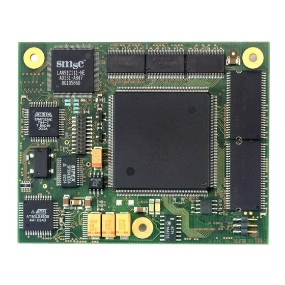
- Page 15 USB Host Interface Connector Power-on SW Reset SW Front view InfraRed Tx System Reset Switch LCD Panel Interface Connector 8bit S it h Expansion Slot Serial Interface Connector SH7727 eTRON Card Connector Rear view Figure 1.5 CPU Board - External View...
- Page 16 R0P7727TH003TRKE General Information Manual Outline 8bit LED Expansion Slot Test Pin TP3(GND) EPROM TP2(Reset) TP1(NMI) EPROM selection jumper switch Emulator selection jumper switch JTAG Connector Figure 1.6 Debug Board - External View...
-
Page 17: T-Engine Specifications
TFT color LCD module LS037V7DW01(SHARP) Display color: 262,144 colors Display area: 240(H) x 320(V) Controller:SH7727 on-chip LCDC Power supply controller H8/3048F-ONE The control SH7727 working for Model name: HD64F3048BVTF25V power supply control, RTC, or tablet (Renesas Technology) interface infrared remote control Operating frequency: 7.3728MHz... - Page 18 R0P7727TH003TRKE General Information Manual Outline Table 1.2 Power supply, Dimensions, and Environmental Specifications of the T-Engine Board Item Specifications Operating conditions Environment - Temperature: 10-35ºC - Humidity: 30 to 85% RH (no dew condensation occurs) Ambient gas: no corrosive gas Operating voltage DC 5.6VDC Dissipation current...
-
Page 19: Installation
R0P7727TH003TRKE General Information Manual Installation 2. Installation 2.1 Host System Connection To use T-monitor, connect the serial interface connector (CN1) of the T-Engine board with an RS-232C interface cable (accessory). Figure 2.1 shows the host system connection method. Figure 2.2 shows the pins of the serial interface connector. -
Page 20: Ac Adapter Connection
R0P7727TH003TRKE General Information Manual Installation Table 2.1 Serial Interface Connector Signals Pin No. Signal name Remarks Output TXB(UART) RXB(UART) RTSB(UART) CTSB(UART) Reserved Reserved Reserved Reserved Reserved Reserved Reserved Reserved Reserved 2.2 AC Adapter Connection Figure 2.3 shows an AC adapter connection method. As shown in Figure 2.3, connect the plug to the AC adapter connector of the T-Engine board (1), then connect the adapter cord to the receptacle (2). -
Page 21: Turning On Or Off The T-Engine Board
For details on flash memory refresh, refer to 10. “Flash Memory Refresh.” (2) All 8-bit LEDs on the debug board can be turned on or off from the SH7727. The software execution state can be monitored by controlling the ON/OFF state of these LEDs. -
Page 22: Debug Board Connection
R0P7727TH003TRKE General Information Manual Installation 2.4.2 Debug Board Connection Figure 2.4 shows a debug board connection method. Connect the debug board to the expansion slot (CN2) on the T-Engine board. T-Engine Board Extension slot (CN2) Connection Extension slot (CN1) Figure 2.4 Debug Board Connection CAUTION Turn off the T-Engine before connecting the debug board or detaching the EPROM. -
Page 23: Debug Board Jumper Switches
Jumper Setting Description switch Debug board resources are assigned to area 0 on the SH7727 board as shown below. (Factory setting) - The flash memory on the T-Engine board is assigned to an address range from h’00000000 to h’00FFFFFF. - The EPROM mounted on the debug board is assigned to an address range Pins 1 and 2 from h’01000000 to h’01FFFFFF. -
Page 24: 8-Bit Leds On The Debug Board
2.4.4 8-bit LEDs on the Debug Board The low-order 8 bits (D7 to D0) of the SH7727 data bus are connected to the 8-bit LEDs placed on the debug board. The 8-bit LEDs can be turned on or off by writing data to an area assigned for the LEDs through D7 to D0. -
Page 25: Switches
(1) to (5). CN10 SW2 SW3 NMI SW Power-on SW Reset SW Front view System Reset Switch 8bit S it h SH7727 Rear view Figure 3.1 CPU Board Switches (SW1 to SW5) - Page 26 ON: T-Engine is powered when power supply takes place through the AC adapter. OFF: T-Engine is powered when the power-on switch is pressed. (Factory setting) (c) The SW5-8 switch is connected to SH7727's pin MD5. The SW5-8 switch is used to set the type of endian for SH7727 operation.
-
Page 27: Lcd Board Switch
3.2 LCD Board Switch 3.2.1 Application Switch The states of the cursor switch (SW1) and push-button switches (SW2 and SW3) are signaled to the SH7727 through the power supply controller. For details, refer to 6. “Power Supply Controller.” 3.2.2 LCD configuration switch Figure 3.3 shows the setting of an 4-bit DIP switch (SW4). -
Page 28: Memory Map
Memory Map 4. Memory Map 4.1 Memory Map for the T-Engine Board Table 4.1 shows an SH7727 memory map for the T-Engine board without expansion board. Table 4.1 SH7727 Memory Map for T-Engine without Expansion Board Area No. Bus width... -
Page 29: Memory Map During Debug Board Connection
Table 4.2 shows a memory map for the SH7727 when the debug board is connected to the T-Engine board and the jumper switch (J1) on the debug board is open. Table 4.3 also shows a memory map for the SH7727 when the debug board is connected to the T-Engine board and the jumper switch (J1) on the debug board is open. - Page 30 Flash memory area S29JL064H70TFI000(Spansion)×1 h’017FFFFF h’02000000 Unused area h’03FFFFFF Area 1 h’04000000 SH7727 internal area h’07FFFFFF Area 2 8/16/32bit h’08000000 64MB Daughter board extended area 2 Extended area h’0BFFFFFF The user can use this area arbitrarily via the expansion slot (/CS2)
-
Page 31: Functional Blocks
(7) Internal interrupt steering function (8) Power-down function (9) Internal suspend function There are four kinds of controller interrupts (SIRQ3 to SIRQ0). It connects with IRQ4 of SH7727 as an interruption of one. For details, refer to Marubun’s MR-SHPC-01 V2-F Manual. Marubun Homepage: http://www.marubun.co.jp/en/index.html... -
Page 32: Connector Pins
R0P7727TH003TRKE General Information Manual Functional Blocks 5.1.2 Connector Pins Table 5.1(1), (2) summarizes the pins of a 68-pin PC card interface connector (CN3). Table 5.1(1) PC Card Interface Connector Signal Pins Memory card I/O card Signal name I/O Function Signal name Function Ground Ground... - Page 33 R0P7727TH003TRKE General Information Manual Functional Blocks Table 5.1(2) PC Card Interface Connector Signal Pins Memory card I/O card Signal Function Signal name Function name Ground Ground CD1# Card detection CD1# Card detection Data bit 11 Data bit 11 Data bit 12 Data bit 12 Data bit 13 Data bit 13...
-
Page 34: Register Map
R0P7727TH003TRKE General Information Manual Functional Blocks 5.1.3 Register Map Table 5.2 shows a map for the PCMCIP controller registers. Each of the controller registers must be accessed in words. Table 5.2 PCMCIA Control Registers Address Initial value Register name H’B83FFFE4 H’0000 Mode register H’B83FFFE6... -
Page 35: Usb Host
5.2 USB Host 5.2.1 Block Description Figure 5.2 shows the USB host control block. As shown in Figure 5.2, the SH7727 contains the internal USB host controller. This internal controller supports USB Versions 1.1 openHCI has the following features: (1) Compatibility with the OpenHCI Version 1.0a register set (2) Conforms to the USB Version 1.1... -
Page 36: Connector Pins
Model name: 20-5041-004-10-834S+ +DATA Maker: Kyocera Elco Figure 5.3 USB Host Connector (CN7) Pins 5.2.3 Register Map Table 5.3 shows a register map for the internal USB host controller of the SH7727. Table5.3 USB Host Controller Register Asddress Initial value Register name H’A4000000... -
Page 37: Uart
In addition, channel A (INTA) inputs the controller interrupts to the SH7727 PINT6 and channel B (INTB) inputs them to the SH7727 PNT7. Because the INTA and INTB interrupts are “High active,” settings must be made in such a way that PINT6 and PINT7 interrupt requests can be detected at High level. -
Page 38: Connector Pins
R0P7727TH003TRKE General Information Manual Functional Blocks 5.3.2 Connector Pins Figure 5.5 shows the pins of a 15-pin serial interface connector (CN1). Signal name Pin No. Reserved Reserved CN1: 16-pin serial connector Reserved Model name: LX60-16S Reserved Maker: HIROSE ELECTRIC CO., LTD Reserved Reserved Reserved... -
Page 39: Register Map
R0P7727TH003TRKE General Information Manual Functional Blocks 5.3.3 Register Map Tables 5.4 and 5.5 show register maps for the serial interface controller registers. Each of the serial interface control registers must be accessed in words. If access takes place in words, data in the low order 8 bits (D7 to D0) will become effective. -
Page 40: Lcd
The front light on the LCD panel can be turned on or off by the power supply controller. For details on front light control, refer to 6. “Power Supply Controller.” In addition, refer to the pertinent SH7727 Hardware Manual for details on the LCD controller. -
Page 41: Connector Pins
R0P7727TH003TRKE General Information Manual Functional Blocks 5.4.2 Connector Pins Figure 5.7 shows the pins of the LCD interface connectors (CN5 and CN6). Tables 5.6 and 5.7 summarize the signals of these interface connectors. CN5: LCD interface connector CN6: LCD interface connector Model name: FH12-40S-0.5SH(55) Model name: FH12-24S-0.5SH(55) Maker: HIROSE ELECTRIC Co.,LTD. -
Page 42: Register Map
R0P7727TH003TRKE General Information Manual Functional Blocks Table5.7 LCD Interface Connector (CN6) Signals Pin No. Signal name Remarks Pin No. Signal name Remarks Power supply ~PAD_CS PAD I/F Power supply ~PAD_IRQ PAD_I/F KEY_IN0 KEY_I/F PAD_DIN PAD_I/F KEY_IN1 KEY_I/F PAD_DOUT PAD_I/F KEY_IN2 KEY_I/F PAD_DCLK PAD_I/F... -
Page 43: Sound Generator
The control method is shown below. Low-level output takes place from SH7727 PTK0 to produce low-level input to the PWAD and PWDA pins of the AK4550 causing a power-down state. This duration is maintained for 150ns or more, then high-level output takes place from SH7727 PKT0 to produce high-level input to the PWAD and PWDA pins of the AK4550, causing a normal operating state. - Page 44 PTK1 Power supply controller Crystal Crystal 2.048MHz 11.2896MHz Figure 5.8 Sound Generator Control Block 150ns (Min) SH7727 port K (PTK0) AK4550 /PWAD pin 2081/fs AK4550 ADC state Normal Operation Power-down Init Cycle Normal Operation AK4550 /PWDA pin AK4550 DAC state...
-
Page 45: Connector Pins
R0P7727TH003TRKE General Information Manual Functional Blocks 5.5.2 Connector Pins Figure 5.10 shows the pins of the sound generator I/O mini-jack (CN8, CN9). Tables 5.9 and 5.10 list the signals of the sound generator I/O mini-jack (CN8, CN9). CN8,9: Sound generator I/O mini-jack(φ2.5) Model name: STX-2550-5NTR Maker: KYCON Figure 5.10 Sound Generator I/O Mini-jack (CN15, CN16) Pins... -
Page 46: Register Map
R0P7727TH003TRKE General Information Manual Functional Blocks 5.5.3 Register Map Table 5.11 shows a register map for the SH7727 SIOF registers. Table 5.11 SIOF Controller Register Address Initial value Register name H’A40000C0 H’0000 Srial mode register H’A40000C2 H’0000 Clock select register H’A40000C4... -
Page 47: Etron Interface
8-pin connector (CN4) to interact with the eTRON card inserted into the eTRON interface connector (CN4). The eTRON card can be reset by controlling the SH7727 port (PTE4). The control method is shown below. “Low” output from PTE4: The reset pin of the eTRON card is set to “Low.” (Reset state) “High”... -
Page 48: Connector Pins
R0P7727TH003TRKE General Information Manual Functional Blocks 5.6.2 Connector Pins Figure 5.12 shows the pins of the SIM card interface connector (CN4). Table 5.12 summarizes the signals of the SIM card interface connector (CN4). CN4: eTRON interface connector Model name: 04-5036-008-210-862+ Maker: KYOCERA ELCO Figure 5.12 eTRON Interface Connector (CN4) Pins Table 5.12 eTRON Interface Connector (CN4) Signals... -
Page 49: Register Map
R0P7727TH003TRKE General Information Manual Functional Blocks 5.6.3 Register Map Table 5.13 shows a register map for the SH7727 internal smart card interface (SCI) controller, including the SIMCRT registers within the FPGA. Table 5.13 SIM Card Module Register Map Address Initial value Register name H’FFFFFE80... -
Page 50: Power Supply Controller
The following functions can be controlled through the UART ChA from the SH7727. Figure 6.1 shows a power supply controller block diagram. (1) RTC (real-time clock) function (2) System power supply (3.3V/5/0V) ON/OFF control function... - Page 51 R0P7727TH003TRKE General Information Manual Power Supply Controller...
-
Page 52: Serial Communications Between Sh7727 And The Power Supply Controller
Power Supply Controller 6.2 Serial Communications between SH7727 and the Power Supply Controller This section describes how serial communications take place between SH7727 and the power supply controller. 6.2.1 Serial Format This subsection describes a format for serial communications between SH7727 and the power supply controller. -
Page 53: Read Command
R0P7727TH003TRKE General Information Manual Power Supply Controller 6.2.3 Read Command Figure 6.2 shows a read command format. SH7727 sends a start code, a function code and a register address, in this order, as a read command. (1) Start code (1 byte) -
Page 54: Normal Response During A Read Operation
R0P7727TH003TRKE General Information Manual Power Supply Controller 6.2.4 Normal Response during a Read Operation Figure 6.5 shows the response format for the read command. The power supply controller returns an ACK code, a function code, a register address and target data, in this order, as a response. (2) Function code (3) Register address (1) ACK code(1 byte) -
Page 55: Power Supply Control Register Write Procedure
6.2.7 Write Command Figure 6.7 shows the write command format. SH7727 sends a start code, a function code, a register address and data, in this order, as a write command. -
Page 56: Normal Response During A Write Operation
R0P7727TH003TRKE General Information Manual Power Supply Controller 6.2.8 Normal Response during a Write Operation Figure 6.10 shows the response format for the write command. The power supply controller returns an ACK code, a function code, a register address and target data, in this order, as a response for the write command. -
Page 57: Error Response During A Write Operation
R0P7727TH003TRKE General Information Manual Power Supply Controller 6.2.9 Error Response during a Write Operation Figure 6.11 shows an error response format for the write command at error occurrence. The power supply controller returns a NAK code and an error code in this order as an error response. (1) NAK code (2) Error code (1 byte) -
Page 58: Rtc (Real-Time Clock) Functions
R0P7727TH003TRKE General Information Manual Power Supply Controller 6.3 RTC (Real-time Clock) Functions This section describes the RTC functions. Table 6.3 summarizes the RTC registers. For a detailed description of each register, refer to 6.3.1 to 6.3.17. (1) Function for counting the seconds, minutes, hours, day of the week, month, and year (BCD code) (2) RTC start/stop function (3) Alarm interrupt function (4) 1sec/0.5sec cyclic interrupt function... -
Page 59: Rtc Control Register (Rtccr)
R0P7727TH003TRKE General Information Manual Power Supply Controller 6.3.1 RTC Control Register (RTCCR) Address: 0x000 Initial value: 0x00 CNTS SECCAF 0.5secI 1secI START (1) START START bit Setting RTC start (Initial value) RTC stop CAUTION Don’t write to any counter while the START bit is set to “0.” Rewrite each counter after setting the START bit to “1.”... -
Page 60: Rtc Status Register (Rtcsr)
R0P7727TH003TRKE General Information Manual Power Supply Controller (6) CNTS CNTS bit Setting The setting (value) of each counter is not updated. (Initial value) The setting (value) of each counter is updated. [Zero-clear condition] Counter update is completed. This clear operation is automatically performed. 6.3.2 RTC Status Register (RTCSR) Address: 0x001 Initial value: 0x00 0.5 secF... -
Page 61: Second Counter (Seccnt)
R0P7727TH003TRKE General Information Manual Power Supply Controller 6.3.3 Second Counter (SECCNT) Address: 0x002 Initial value: 0xXX (Not defined) 10 seconds 1 second The counter value is a BCD (Binary Coded Decimal) value. Counting takes place within a range from 00 to 59. When the value changes from 59 to 00, a carry is generated in the minute counter. -
Page 62: Day-Of-The-Week Counter (Wkcnt)
R0P7727TH003TRKE General Information Manual Power Supply Controller 6.3.6 Day-of-the-Week Counter (WKCNT) Address: 0x0005 Initial Value: 0xXX (Not defined) Septinary incremental counter Counting takes place within a range from 0x00 to 0x06. The following shows the correspondence between the day of the week and the value of the septinary incremental counter. -
Page 63: Year Counter (Yrcnt)
R0P7727TH003TRKE General Information Manual Power Supply Controller 6.3.9 Year Counter (YRCNT) Address: 0x0008 Initial value: 0xXX (Not defined) 10 years 1 year The counter value is a BCD (Binary Coded Decimal) value. Counting takes place within a range from 0 to 99. In this range, 00, 04, ..., 92 and 96 are leap years. -
Page 64: Hour Alarm Register (Hrar)
R0P7727TH003TRKE General Information Manual Power Supply Controller 6.3.13 Hour Alarm Register (HRAR) Address: 0x000B Initial value: 0x00 10 hours 1 hour The alarm value must be a BCD (Binary Coded Decimal) code between 00 and 23. 6.3.14 Day-of-the-Week Alarm Register (WKAR) Address: 0x000C Initial value: 0x00 Septinary counter value The alarm value must be set within a range from 0x00 to 0x06. -
Page 65: Day Alarm Register (Dayar)
R0P7727TH003TRKE General Information Manual Power Supply Controller 6.3.15 Day Alarm Register (DAYAR) Address: 0x000D Initial value: 0x00 10 days 1 day The alarm value must be a BCD (Binary Coded Decimal) code between 1 and 31 (January, March, May, July, August, October and December), between 1 and 30 (April, June, September and November), between 1 and 28 (February in normal year) or between 1 and 29 (February in leap year). -
Page 66: Touch Panel Functions
X or Y position) obtained three times from sampling are approximate to each other, a pen touch ON interrupt is generated for SH7727. In addition, when the touch panel is turned off, a pen touch OFF interrupt is generated. - Page 67 R0P7727TH003TRKE General Information Manual Power Supply Controller Table 6.4 Touch Panel Registers Register Abbreviation Address Size Remarks Touch panel control register TPLCR 0x0020 1 byte Touch panel status register TPLSR 0x0021 1 byte Touch panel sampling control register TPLSCR 0x0022 1 byte X position A/D register XPAR...
-
Page 68: Touch Panel Control Register (Tplcr)
R0P7727TH003TRKE General Information Manual Power Supply Controller 6.4.1 Touch Panel Control Register (TPLCR) Address: 0x0020 Initial value: 0x00 PEN_OFFI PEN_ONI TP_STR PEN_ONRE (1) TP_STR TP_STR bit Setting The touch panel is disabled. (Initial value) The touch panel is enabled. (2) PEN_ONI PEN_ONI bit Setting A pen touch ON interrupt is not generated. -
Page 69: Touch Panel Status Register (Tplsr)
R0P7727TH003TRKE General Information Manual Power Supply Controller 6.4.2 Touch Panel Status Register (TPLSR) Address: 0x0021 Initial value: 0x00 PEN_OFFIF PEN_ONIF (1) PEN_ONIF PEN_ONIF bit Setting The touch panel has not been pen-touched. (pen touch OFF.) (Initial value) The pen-touch state on the touch panel has been changed from OFF to ON. -
Page 70: Touch Panel Sampling Control Register (Tplscr)
R0P7727TH003TRKE General Information Manual Power Supply Controller 6.4.3 Touch panel Sampling Control Register (TPLSCR) The touch panel sampling control register sets a sampling interval for the touch panel. Address: 0x0022 Initial value: 0x01 160mse 140msec 120msec 100msec 80msec 60msec 40msec 20msec A sampling interval for the touch panel can be set within a range from 20msec to 160msec (unit: 20msec). -
Page 71: Y Position A/D Register (Ypar)
R0P7727TH003TRKE General Information Manual Power Supply Controller 6.4.5 Y Position A/D Register (YPAR) Address: 0x0026 Initial value: 0x0000 YA_D11 YA_D10 YA_D9 YA_D8 YA_D7 YA_D6 YA_D5 YA_D4 YA_D3 YA_D2 YA_D1 YA_D0 The Y position A/D register indicates the A/D conversion result of a pen-touched Y position on the touch panel. 6.4.6 X Position Dot Register (XPDR) Address: 0x0028 Initial value: 0x0000 XD_D15... -
Page 72: Xa Position Dot Register (Xapdr)
R0P7727TH003TRKE General Information Manual Power Supply Controller 6.4.8 XA Position Dot Register (XAPDR) Address: 0x002C Initial value: 0x0000 XAD_D1 XAD_D15 XAD_D14 XAD_D13 XAD_D12 XAD_D11 XAD_D9 XAD_D8 XAD_D7 XAD_D6 XAD_D5 XAD_D4 XAD_D3 XAD_D2 XAD_D1 XAD_D0 The XA position dot register indicates the X dot position of point A when calibration takes place. 6.4.9 YA Position Dot Register (YAPDR) Address: 0x002E Initial value: 0x0000 YAD_D15... -
Page 73: Yb Position Dot Register (Ybpdr)
R0P7727TH003TRKE General Information Manual Power Supply Controller 6.4.11 YB Position Dot Register (YBPDR) Address: 0x0032 Initial value: 0x0000 YBD_D15 YBD_D14 YBD_D13 YBD_D12 YBD_D11 YBD_D10 YBD_D9 YBD_D8 YBD_D7 YBD_D6 YBD_D5 YBD_D4 YBD_D3 YBD_D2 YBD_D1 YBD_D0 The YB position dot register indicates the Y dot position of point B when calibration takes place. 6.4.12 XC Position Dot Register (XCPDR) Address: 0x0034 Initial value: 0x0000 XCD_D15... -
Page 74: Xa Position A/D Register (Xapar)
R0P7727TH003TRKE General Information Manual Power Supply Controller 6.4.14 XA Position A/D Register (XAPAR) Address: 0x0038 Initial value: 0x0000 XAA_D11 XAA_D10 XAA_D9 XAA_D8 XAA_D7 XAA_D6 XAA_D5 XAA_D4 XAA_D3 XAA_D2 XAA_D1 XAA_D0 The XA position A/D register indicates the X position A/D conversion result of point A subject to calibration/ 6.4.15 YA Position A/D Register (YAPAR) Address: 0x003A Initial value: 0x0000 YAA_D11... -
Page 75: Yb Position A/D Register (Ybpar)
R0P7727TH003TRKE General Information Manual Power Supply Controller 6.4.17 YB Position A/D Register (YBPAR) Address: 0x003E Initial value: 0x0000 YBA_D11 YBA_D10 YBA_D9 YBA_D8 YBA_D7 YBA_D6 YBA_D5 YBA_D4 YBA_D3 YBA_D2 YBA_D1 YBA_D0 The YB position A/D register indicates the Y position A/D conversion result of point B subject to calibration. 6.4.18 XC Position A/D Register (XCPAR) Address: 0x0040 Initial value: 0x0000 XCA_D11... -
Page 76: Dx Dot Register (Dxdr)
R0P7727TH003TRKE General Information Manual Power Supply Controller 6.4.20 DX Dot Register (DXDR) Address: 0x0044 Initial value: 0x0000 DX1_D15 DX1_D14 DX1_D13 DX1_D12 DX1_D11 DX1_D10 DX1_D9 DX1_D8 DX1_D7 DX1_D6 DX1_D5 DX1_D4 DX1_D3 DX1_D2 DX1_D1 DX1_D0 The DX dot register holds a value obtained by multiplying the number of dots per data (X position A/D conversion result at calibration) by 1,000. -
Page 77: Position Dot Calculation A/D Value (Xpardot)
R0P7727TH003TRKE General Information Manual Power Supply Controller 6.4.22 X Position Dot Calculation A/D Value (XPARDOT) Address: 0X0048 Initial value: 0x0000 XD_D9 XD_D8 XD_D7 XD_D6 XD_D5 XD_D4 XD_D3 The X position dot calculation A/D value register (XPARDOT) holds an AD value of X position dot calculation. This A/D value is obtained by calculating the mean of the previous four XPARDOT values and clearing the low order 3 bits with zeros. -
Page 78: Position Dot Calculation A/D Value 3 (Xpardot3)
R0P7727TH003TRKE General Information Manual Power Supply Controller 6.4.25 X Position Dot Calculation A/D Value 3 (XPARDOT3) Address: 0x004E Initial value: 0x0000 XD3_D9 XD3_D8 XD3_D7 XD3_D6 XD3_D5 XD3_D4 XD3_D3 The X position dot calculation A/D value 3 register (XPARDOT3) holds an XPARDOT value before sampling. -
Page 79: Y Position Dot Calculation A/D Value 1 (Ypardot1)
R0P7727TH003TRKE General Information Manual Power Supply Controller 6.4.28 Y Position Dot Calculation A/D Value 1 (YPARDOT1) Address: 0 x0054 Initial value: 0x0000 YD1_D9 YD1_D8 YD1_D7 YD1_D6 YD1_D5 YD1_D4 YD1_D3 The Y position dot calculation A/D value 1 register (YPARDOT1) holds a YPARDOT value before sampling. 6.4.29 Y Position Dot Calculation A/D Value 2 (YPARDOT2) Address: 0x0056 Initial value: 0x0000... -
Page 80: Y Position Dot Calculation A/D Value 4 (Ypardot4)
R0P7727TH003TRKE General Information Manual Power Supply Controller 6.4.31 Y Position Dot Calculation A/D Value 4 (YPARDOT4) Address: 0x005A Initial value: 0x0000 YD4_D9 YD4_D8 YD4_D7 YD4_D6 YD4_D5 YD4_D4 YD4_D3 The Y position dot calculation A/D value 4 register (YPARDOT4) holds a YPARDOT value before sampling. -
Page 81: Touch Panel Calibration Method (2-Point System)
R0P7727TH003TRKE General Information Manual Power Supply Controller 6.4.33 Touch Panel Calibration Method (2-point System) The power supply controller supports 2-point touch panel calibration. Figure 6.11shows the points of the drawing coordinates and A/D conversion coordinates that are necessary for calibration. Origin of drawing coordinates T-Engine Board... - Page 82 (4) Calibration takes place according to data in the above steps (1) to (3). Using the following expression, the SH7727 calculates the number of dots per data of the X position A/D conversion result and that of the Y position A/D conversion result.
-
Page 83: Key Switch Control
R0P7727TH003TRKE General Information Manual Power Supply Controller 6.5 Key Switch Control Figure 6.12 shows the T-Engine switches under control by the power supply controller. The power supply controller controls the switches SW1 to SW3 on the CPU board and the switches SW1to SW3 on the LCD board. -
Page 84: Cpu Board Switch Control
6.5.1 CPU Board Switch Control (1) Power-on switch (SW1) When the SH7727 is being powered, a power-on switch interrupt occurs for the SH7727 if the power-on switch is pressed and held for 2 seconds or more. When T-Engine is OFF, it is turned ON if the power-on switch is pressed and held for 0.5 seconds or more. -
Page 85: Key Control Register (Keycr)
A power-on switch interrupt is enabled. (6) NMIE NMIE bit Setting An NMI interrupt is disabled for the SH7727 even when the NMI switch is pressed. An NMI interrupt is disabled for the SH7727 when the NMI switch is pressed. (Initial value) -
Page 86: Key Auto Repeat Time Register (Katimer)
R0P7727TH003TRKE General Information Manual Power Supply Controller 6.5.5 Key Auto Repeat Time Register (KATIMER) Address: 0x0061 Initial value: 0x01 450msec 400msec 350msec 300msec 250msec 200msec 150msec 100msec This register sets the auto repeat interrupt generation time. The auto repeat interrupt generation time is set at intervals of 100msec to 450msec (unit: 50msec). -
Page 87: Key Input Status Register (Keysr)
R0P7727TH003TRKE General Information Manual Power Supply Controller 6.5.7 Key Input Status Register (KEYSR) Address: 0x0062 Initial value: 0x00 PONSWF ARKEYF KEY_OFFF KEY_ONF (1) KEY_ONF KEY_ONF bit Setting An application switch key has not been turned on (Initial value) An application switch key has been turned on. At this time, if the KEY_ONI bit is set to ‘’1,’’... - Page 88 R0P7727TH003TRKE General Information Manual Power Supply Controller [Supplementary description on application switch key input] (1) When multiple keys are pressed at the same time, the corresponding bits are all set to “1,” and a KEY_ONF interrupt occurs so long as it is enabled. (2) If data in the key bit pattern register changes when multiple keys are pressed at the same time, a KEY_ONF interrupt occurs so long as it is enabled.
-
Page 89: Rtc/Touch Panel/Key Input/Power Supply Status Register (Rtkisr)
(2) When T-Engine is OFF, it is turned ON if the power-on switch is pressed for 2 seconds or more. (3) T-Engine can be turned OFF from the SH7727. (4) If the DIP switch (SW7) is set to ON, T-Engine is also turned ON at the same time the power supply controller is turned ON. -
Page 90: System Power Control Register 1 (Spowcr1)
(2) SFPOWER SFPOWER Setting T-Engine is turned OFF by SH7727 control. T-Engine is turned OFF by pressing the power-on switch. (Initial value) 6.6.3 RTC/Touch Panel/Key Input/Power Supply Status Register (RTKISR) This status register indicates the RTC, touch panel, or key input status. Below is a brief description of the status bits for power control. -
Page 91: Led Control
This section describes the LED control functions. Table 6.7 summarizes the LED control registers. Though SH7727 T-Engine has not been provided with LED1 to LED8, LED control is executed. (1) Controlling the ON/OFF State of LEDs (LED1 to LED8) on the CPU board Table 6.7 LED control register... -
Page 92: Lcd Front Light Register (Lcdr)
R0P7727TH003TRKE General Information Manual Power Supply Controller 6.8.1 LCD Front Light Register (LCDR) Address: 0x00A1 Initial value: 0x01 FRONTL (1) FRONTL FRONTL bit Setting The LCD front light is turned ON. The LCD front light is turned OFF. (Initial value) 6.9 Reset Control This section describes the reset control functions. -
Page 93: Infrared Remote Control
R0P7727TH003TRKE General Information Manual Power Supply Controller 6.10 Infrared Remote Control This section describes the infrared remote control functions. Table 6.10 summarizes the infrared remote control functions. For details of each register, refer to 6.10.1 to 6.10.8. (1) Support of formats for two kinds of infrared remote control signal •... -
Page 94: Infrared Remote Control Register (Irrcr)
R0P7727TH003TRKE General Information Manual Power Supply Controller 6.10.1 Infrared Remote Control Register (IRRCR) Address; 0x00B0 Initial value: 0x00 TDIE RDIE FORMAT START (1) START START bit Setting control is disabled. (Initial value) Infrared remote control is enabled to start data transmission/reception. (2) FORMAT FORMAT bit Setting... -
Page 95: Infrared Remote Control Status Register (Irrsr)
R0P7727TH003TRKE General Information Manual Power Supply Controller 6.10.2 Infrared Remote Control Status Register (IRRSR) Address: 0x00B1 Initial value: 0x00 RDBFE (1) RDBFER RDBFER bit Setting A buffer full error has not occurred during a receive operation. (Initial value) A buffer full error has occurred during a receive operation. (2) RDI RDI bit Setting... -
Page 96: Transmit Data Count Register For Infrared Remote Control Signals (Irrsdnr)
R0P7727TH003TRKE General Information Manual Power Supply Controller 6.10.4 Transmit Data Count Register for Infrared Remote Control Signals (IRRSDNR) Address: 0x00B3 Initial value: 0x00 IRRSD_D7 IRRSD_D6 IRRSD_D5 IRRSD_D4 IRRSD_D3 IRRSD_D2 IRRSD_D1 IRRSD_D0 This register indicates the number of data items not transmitted (infrared remote control signals) stored in the transmit FIFO register. -
Page 97: Rtc/Touch Panel/Key Input/Power Supply Status Register (Rtkisr)
R0P7727TH003TRKE General Information Manual Power Supply Controller 6.10.7 RTC/Touch Panel/Key Input/Power Supply Status Register (RTKISR) This status register indicates the RTC, touch panel, or key input status. Below is a brief description of the status bits for infrared remote control signals. Address: 0x0090 Initial value: 0x00 IRRIF POWERIF... - Page 98 R0P7727TH003TRKE General Information Manual Power Supply Controller [For infrared signal transmission] (1) When transmission data is transmitted, it is written to the transmitting FIFO data register. The data count for one frame of transmission data and the data itself are written to this data register. In addition, this transmission data count is not counted as transmission data.
-
Page 99: Serial Eeprom Control
R0P7727TH003TRKE General Information Manual Power Supply Controller 6.11 Serial EEPROM Control This section describes the EEPROM control functions. Table 6.11 summarizes the serial EEPROM control registers. For details of each register, refer to 6.11.1 to 6.11.3. (1) Serial EEPROM (512 bytes) can be read and written. Table 6.11 Serial EEPROM Control Registers Register Abbreviation... -
Page 100: Eeprom Data Register (Eepdr)
R0P7727TH003TRKE General Information Manual Power Supply Controller 6.11.3 EEPROM Data Register (EEPDR) Address: 0x0100 to 0x02FF Initial value: Not defined EEPDR_D7 EEPDR_D6 EEPDR_D5 EEPDR_D4 EEPDR_D3 EEPDR_D2 EEPDR_D1 EEPDR_D0 This register consists of 512 8-bit data in the above format. EEPDR address 0x0100 8 bit 0x0101... -
Page 101: Electronic Volume Control
R0P7727TH003TRKE General Information Manual Power Supply Controller 6.12 Electronic Volume Control This section describes the electronic volume control functions. Table 6.12 summarizes the electronic volume control registers. For details of each register, refer to 6.12.1 and 6.12.2. (1) An electronic volume value can be set. An electronic volume value can be set within a range from 0x00 (minimum sound volume) to 0xFF (maximum sound volume). -
Page 102: Power Supply Controller Initial Values
R0P7727TH003TRKE General Information Manual Power Supply Controller 6.13 Power Supply Controller Initial Values The register values for the power supply controller vary depending on the following conditions. Under condition A, all the power supply controller registers are initialized. The initial value of each register is given in the description of each register in this manual. - Page 103 R0P7727TH003TRKE General Information Manual Power Supply Controller Figure 6.14 Values under Touch Panel Register Conditions Register Abbreviation Condition A Condition B Condition C Condition D Touch panel control register TPLCR Initial value Initial value Hold Initial value Touch panel status register TPLSR Initial value Initial value...
- Page 104 R0P7727TH003TRKE General Information Manual Power Supply Controller Table 6.16 Values under Power Supply Control Register Conditions Register Abbreviation Condition A Condition B Condition C Condition D System power control register 1 SPOWCR1 Initial value Initial value Hold 0x00 System power snort register 2 SPOWCR2 Initial value Initial value...
-
Page 105: External Interrupts
7. External Interrupts 7.1 SH7727 External Interrupts Figure 7.1 shows a mechanism for the SH7727 interrupt signal. Table 7.1 shows the levels for respective interrupt signals. As shown in Figure 7.1, interrupt signals from devices within T-Engine are sent to the pins /IRQ4, PINT11, PINT6 and PINT7 of theSH7727. -
Page 106: T-Engine Expansion Slot
R0P7727TH003TRKE General Information Manual T-Engine Expansion Slot 8. T-Engine Expansion Slot 8.1 Expansion Slot Specifications Connector number: CN2 T-Engine connector model: 24-5603-14-0101-861+ (Kyocera Elco) Adaptable connector model: 14-5603-14-0101-861+ (Kyocera Elco) Figure 8.1 shows the location of an expansion slot. 3.00mm 75.00mm Center of 3mm x 3mm Serial interface connector... -
Page 107: Expansion Slot Signal Assignment
*1: 5.0V (typ.) is supplied when the SH7727 is turned on. *2: If this pin is set to “Low,” output takes place from the SH7727 expansion to the expansion slot. *3: 3.3V (typ.) is supplied when the AC adapter is connected. -
Page 108: Daughter Board Design Guide
This chapter describes the design of the daughter board to be connected to the expansion slot of T-Engine. The daughter board may contain user-specific devices and can be controlled by the address bus, data bus, and control signals or serial signals (start-stop) of the SH7727 that connect to the expansion slots of T-Engine. 9.1 Daughter Board Dimensions The recommended daughter board size is the CPU board size (120mm x 75mm) of T-Engine. -
Page 109: Daughter Board Stack
In addition, the /WAIT pin on T-Engine is subject to pull-up with 680 ohms. Figure 9.3 shows an /WAIT pin structure on the expansion slot. T-Engine board side Daughter board side 3.3V Expansion Expansion SH7727 slot Extended device slot 680Ω Open collector output /WAIT output... -
Page 110: Expansion Slot Ac Timing
9.5 Expansion Slot AC Timing As shown in Figure 9.4, the SH7727 bus signal is output to the expansion slot via the bus buffer. For this reason, the bus signal delays approx. 8nsec for the AC timing of the SH7727 bus. When designing the daughter board, consider this delay. - Page 111 R0P7727TH003TRKE General Information Manual Daughter Board Design Guide ACタイミング...
-
Page 112: Flash Memory Refresh
Debug board jumper switch (J1): Pins 1 and 2 must be short-circuited (EPROM allocation to an address range from h’00000000 to h’00FFFFFF). Debug board jumper switch 2 (J2): Pins 1 and 2 must be open (SH7727 normal operation). Connect the serial interface connector (CN1) of T-Engine and host system with an RS-232C interface cable (accessory). -
Page 113: T-Engine Flash Memory
R0P7727TH003TRKE General Information Manual Flash Memory Refresh 10.2 T-Engine Flash Memory 10.2.1 Refresh Method Figure 10.1 shows how the T-Engine flash memory is refreshed. As shown in Figure 10.1, the T-Engine flash memory is refreshed in such a way that flash memory data is copied to SDRAM and the data transferred from the host system is written to the flash memory. - Page 114 “Please Send A S-format Record” appears on the screen. [Display Screen] Ready>fl 0 SH7727 Flash Memory Change Value! Flash Memory data copy to RAM Please Send A S-format Record (3) Flash memory refresh normally terminates when the messages (“flash memory chip erase: complete”...
- Page 115 SH7727 T-Engine General Information Manual R0P7727TH003TRKE Publication Date Mar. 2008 Rev.1.00 Published by Renesas Solutions Corp. Microcomputer Tool Marketing Department Renesas Solutions Corp. Edit by Microcomputer Tool Marketing Department © 2008. Renesas Technology Corp. and Renesas Solutions Corp., All rights reserved. Printed in Japan.
- Page 116 R0P7727TH003TRKE General Information Manual...
Need help?
Do you have a question about the SH7727 and is the answer not in the manual?
Questions and answers