
Related Manuals for Keysight N5166B CXG


Summary of Contents for Keysight N5166B CXG
- Page 1 Keysight N5166B CXG N5171B/72B/73B EXG N5181B/82B/83B MXG X-Series Signal Generators User’s Guide...
- Page 2 PERFORMANCE OF THIS to the public to use, modify, DOCUMENT OR ANY INFORMATION reproduce, release, perform, CONTAINED HEREIN. SHOULD display, or disclose commercial KEYSIGHT AND THE USER HAVE A computer software or SEPARATE WRITTEN AGREEMENT commercial computer software WITH WARRANTY TERMS...
-
Page 3: These Features Are Available Only In N5172B/82B Vector Signal Generators With Options
URLs, according to the name of your product: http://www.keysight.com/find/X-Series_SG To receive the latest updates by email, subscribe to Keysight Email Updates at the following URL: http://www.keysight.com/find/MyKeysight Information on preventing instrument damage can be found at: www.keysight.com/find/PreventingInstrumentRepair... -
Page 5: Table Of Contents
Contents Table of Contents 1. Signal Generator Overview Signal Generator Features ..............20 Modes of Operation . - Page 6 Contents 5. PULSE ................31 6.
- Page 7 Contents Viewing Options and Licenses ............. . 56 Hardware Assembly Installation and Removal Softkeys .
- Page 8 Contents Configure Internal Channel Correction ............114 Perform Enhanced Factory Calibration.
- Page 9 Contents To set the ILS Localizer DDM value as a percentage (%) ......... 157 To set the ILS Localizer SDM value.
- Page 10 Contents I/Q Modulation ................202 Configuring the Front Panel Inputs.
- Page 11 Contents Setting the Baseband Frequency Offset............261 DAC Over–Range Conditions and Scaling .
- Page 12 Contents Choosing the Logic Type and Port Configuration..........322 Selecting the Output Direction .
- Page 13 Contents Using Real-Time Fading Softkeys ............. . 378 To configure a Real-Time Fading simulation .
- Page 14 Returning a Signal Generator to Keysight ........
- Page 15 Contents How to Obtain the Security Features Document ........... 459 Using Secure Display (Option 006).
- Page 16 Contents...
- Page 17 Documentation Overview — Safety Information Getting Started Guide — Receiving the Instrument — Environmental & Electrical Requirements — Basic Setup — Accessories — Operation Verification — Regulatory Information — Signal Generator Overview User’s Guide — Preferences & Enabling Options — Basic Operation —...
- Page 18 — Provides a listing of SCPI commands and programming codes for Programming signal generator models that are supported by the Keysight CXG, Compatibility Guide EXG, and MXG X- Series signal generators. — Troubleshooting Service Guide — Replaceable Parts — Assembly Replacement —...
-
Page 19: Signal Generator Overview
To avoid damaging or degrading the performance of the instrument, do not exceed 33 dBm (2W) maximum (27 dBm (0.5W) for N5173N/83B) of reverse power levels at the RF input. See also Tips for Preventing Signal Generator Damage on www.keysight.com. — Signal Generator Features on page 20 —... -
Page 20: Signal Generator Features
— LF multifunction generator (Option 303) — narrow pulse modulation, including internal pulse generator (Option UNW) — analog differential I/Q outputs (vector models, Option 1EL) — analog modulation: AM, FM, and ΦM (Option UNT) Keysight CXG, EXG, and MXG X-Series Signal Generators User’s Guide... -
Page 21: Modes Of Operation
— expanded license key upgradability (Option 099) For more details on hardware, firmware, software, and documentation features and options, refer to the data sheet shipped with the signal generator and available from the Keysight Technologies website at http://www.keysight.com/find/X-Series_SG. Modes of Operation... -
Page 22: Digital Modulation (Vector Models With Option 65X Only)
Custom Arb Waveform Generator mode, or downloaded through a remote interface into the ARB memory. To learn more, refer to “Dual ARB Player” on page 207. Keysight CXG, EXG, and MXG X-Series Signal Generators User’s Guide... -
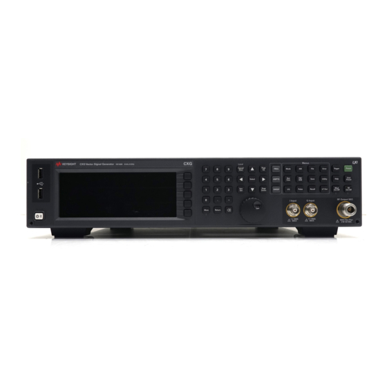
Page 23: Front Panel Overview
The numeric keypad comprises the 0 through 9 hardkeys, a decimal point hardkey, a minus sign hardkey, and a backspace hardkey. See “Entering and Editing Numbers and Text” on page Keysight CXG, EXG, and MXG X-Series Signal Generators User’s Guide... -
Page 24: Arrows And Select
(such an IQ calibration). 10. Help Use this key to display a description of any hardkey or softkey. See “Viewing Key Descriptions” on page Keysight CXG, EXG, and MXG X-Series Signal Generators User’s Guide... -
Page 25: 11. Preset And User Preset
An externally supplied analog, in–phase component of I/Q modulation. The signal level is = 0.5 V for a calibrated output level. Damage Levels See also, “I/Q Modulation” on page 265. Keysight CXG, EXG, and MXG X-Series Signal Generators User’s Guide... -
Page 26: Q Input (Vector Models Only)
LED lights and all signal generator functions deactivate. The signal generator remains connected to the line power, and some power is consumed by some internal circuits. In the on position, the green LED lights and the signal generator functions activate. Keysight CXG, EXG, and MXG X-Series Signal Generators User’s Guide... -
Page 27: Front Panel Display
The internal channel correction is enabled. CHANCORR The ALC detector heater is not up to temperature. To meet ALC specifications the heater must be at DETHTR temperature. The digital bus is in use. DIGBUS Keysight CXG, EXG, and MXG X-Series Signal Generators User’s Guide... -
Page 28: Amplitude Area
This area displays the current output power level setting (If the RF Output is off, this area is greyed out). 5. Error Message Area This area displays abbreviated error messages. If multiple messages occur, only the most recent message remains displayed. See “Reading Error Messages” on page Keysight CXG, EXG, and MXG X-Series Signal Generators User’s Guide... -
Page 29: Text Area
7. Softkey Label Area This area displays labels that define the function of the softkeys located immediately to the right of the display. Softkey labels change, depending on the function selected. Keysight CXG, EXG, and MXG X-Series Signal Generators User’s Guide... -
Page 30: Rear Panel Overview
Error -310 due to the instrument not being powered down correctly. Keysight CXG, EXG, and MXG X-Series Signal Generators User’s Guide... -
Page 31: Ext 1 & Ext 2
60. With Option 1ER (flexible reference input), you must explicitly tell the signal generator the external reference frequency you wish to use; enter the information through the front panel or over the remote interface. Keysight CXG, EXG, and MXG X-Series Signal Generators User’s Guide... -
Page 32: 8. 10 Mhz Out
Use this universal serial bus (USB) to connect a USB Flash Drive (UFD) for data transfer. You can connect or disconnect a USB device without shutting down or restarting the signal generator. 13. SD Card Holds the Secure Digital (SD) nonvolatile memory card. Keysight CXG, EXG, and MXG X-Series Signal Generators User’s Guide... -
Page 33: Digital Modulation Connectors (Vector Models Only)
Output on this connector occurs whenever Marker 1 is on in an Arb–based waveform (see “Using Waveform Markers” on page 223 Damage Levels < −4 and > +8 V Keysight CXG, EXG, and MXG X-Series Signal Generators User’s Guide... -
Page 34: Pat Trig
< −4 and > +8 V DIGITAL BUS I/O This is a proprietary bus used by Keysight Technologies signal creation software. This connector is not operational for general purpose use. Signals are present only when a signal creation software option is installed (for details, refer to http://www.keysight.com/find/signalcreation). -
Page 35: Aux I/O Connector
The AUX I/O connector supports standard 3.3V TTL signaling levels. Signals support data rates up to 50 MHz with minimum rise and fall times of 3ns. Any pins that are not connected will have a weak pull-up to 3.3V. Keysight CXG, EXG, and MXG X-Series Signal Generators User’s Guide... - Page 36 Pin 31 outputs data enable signal for gating external equipment. The output is applicable when the external data is clocked into internally generated timeslots. Data is enabled when the signal is low. Keysight CXG, EXG, and MXG X-Series Signal Generators User’s Guide...
- Page 37 Clock Clock Output AUX(0) AUX(1) AUX(2) AUX(3) AUX(4) AUX(5) AUX(6) AUX I/O AUX(7) BER Meas AUX(8) BER Sync Loss AUX(9) BER Test AUX(10) BER Gate AUX(11) BER No Data AUX(12) Keysight CXG, EXG, and MXG X-Series Signal Generators User’s Guide...
- Page 38 Settings shown are for the Error Out signal configuration of the AUX I/O connector (BERT > I/O Setup > Aux I/O Out). Press the Help hardkey, then either Reference Out or PN9 Out for the respective signal configuration. Keysight CXG, EXG, and MXG X-Series Signal Generators User’s Guide...
-
Page 39: Rear Panel Overview (N5173B & N5183B)
Error -310 due to the instrument not being powered down correctly. Keysight CXG, EXG, and MXG X-Series Signal Generators User’s Guide... -
Page 40: Ext 1 & Ext 2
60. With Option 1ER (flexible reference input), you must explicitly tell the signal generator the external reference frequency you wish to use; enter the information through the front panel or over the remote interface. Keysight CXG, EXG, and MXG X-Series Signal Generators User’s Guide... -
Page 41: 8. 10 Mhz Out
14. ALC INPUT This input connector is used for negative external detector leveling. Connector female BNC Impedance nominally 100 kΩ Signal -0.2 mV to -0.5 V Damage Levels -12 to 1 V Keysight CXG, EXG, and MXG X-Series Signal Generators User’s Guide... -
Page 42: 15. Z Axis Output
This signal is derived from an operational amplifier output so the load impedance should be greater than or equal to 5 kohms.1 Connector female BNC Impedance nominally 50 Ω Signal A nominal signal level greater than 4 dBm. Keysight CXG, EXG, and MXG X-Series Signal Generators User’s Guide... -
Page 43: Preferences & Enabling Options
Keysight Technologies X-Series Signal Generators User’s Guide Preferences & Enabling Options The Utility menu provides access to both user and remote operation preferences, and to the menus in which you can enable instrument options. Remote Operation Preferences on page 49 GPIB Address and Remote Language ... -
Page 44: User Preferences
User Preferences From the Utility menu, you can set the following user preferences: — Display Settings, below — Power On and Preset on page 46 — Front Panel Knob Resolution on page 46 Keysight CXG, EXG, and MXG X-Series Signal Generators User’s Guide... -
Page 45: Display Settings
With the brightness set to minimum, the display may be too dark to see the softkeys. If this happens, use the figure above to locate the brightness softkey and adjust the value so that you can see the display. Keysight CXG, EXG, and MXG X-Series Signal Generators User’s Guide... -
Page 46: Power On And Preset
ALC in open loop mode, this compensates for open loop power drift due to temperature and humidity. SCPI Commands: For details on each key, use key help :CALibration:ALC:MODulator:BIAS page 60 as described on Keysight CXG, EXG, and MXG X-Series Signal Generators User’s Guide... -
Page 47: Setting Time And Date
In this case, you can re-enable the signal generator’s ability to use time–based licenses by moving the clock forward to the original time or simply waiting that length of time. Keysight CXG, EXG, and MXG X-Series Signal Generators User’s Guide... -
Page 48: Reference Oscillator Tune
The range; –8192 to 8192, can be set by using the front panel keypad, knob or remote command. See also the SCPI Command Reference. For details on each key, use key help page 60 as described on Keysight CXG, EXG, and MXG X-Series Signal Generators User’s Guide... -
Page 49: Upgrading Firmware
Press the Clear SCPI Log softkey to clear the log. Select On to view the associated SCPI command for a key press. page 60 For details on each key, use key help as described on Keysight CXG, EXG, and MXG X-Series Signal Generators User’s Guide... -
Page 50: Configuring The Lan Interface
For more information refer to For details on each key, use key help the Programming Guide. as described on page 60. Keysight CXG, EXG, and MXG X-Series Signal Generators User’s Guide... -
Page 51: Configuring The Remote Languages
Figure 2-2 N5166B/71B/72B/81B/82B Utility > I/O Config Select the desired Remote language. For details on each key, use key help Refer to the SCPI Command Reference. page 60 as described on Keysight CXG, EXG, and MXG X-Series Signal Generators User’s Guide... - Page 52 Figure 2-3 N5173B/83B Utility > I/O Config Select the desired Remote language. page 60 For details on each key, use key help as described on Refer to the SCPI Command Reference. Keysight CXG, EXG, and MXG X-Series Signal Generators User’s Guide...
-
Page 53: Configuring The Preset Languages
Figure 2-4 N5166B/71B/72B/81B/82B Utility > Power On/Preset Select the desired Remote language. page 46 Refer to the SCPI Command Reference. For details on each key, use key help page 60 as described on Keysight CXG, EXG, and MXG X-Series Signal Generators User’s Guide... - Page 54 Figure 2-5 N5173B/83B Select the desired Remote language. Utility > Power On/Preset page 46 page 60 For details on each key, use key help as described on Refer to the SCPI Command Reference. Keysight CXG, EXG, and MXG X-Series Signal Generators User’s Guide...
-
Page 55: Enabling An Option
1. Insert the USB flash drive into one of the instrument front panel USB ports. 2. Select the license file. 3. Press Install Licenses. — Use SCPI commands, as described in the SCPI Command Reference. Keysight CXG, EXG, and MXG X-Series Signal Generators User’s Guide... -
Page 56: Viewing Options And Licenses
Waveform licenses from some Signal Studio applications appear here. Service Software Licenses appear here. For details on each key, use key help page 60 as described on Keysight CXG, EXG, and MXG X-Series Signal Generators User’s Guide... -
Page 57: Hardware Assembly Installation And Removal Softkeys
Calibration Factory Calibration to calibrate your instrument. The Enhanced Factory Calibration requires a spectrum analyzer in addition to a power meter. The Factory Calibration uses only a power meter. Keysight CXG, EXG, and MXG X-Series Signal Generators User’s Guide... - Page 58 Preferences & Enabling Options Hardware Assembly Installation and Removal Softkeys Keysight CXG, EXG, and MXG X-Series Signal Generators User’s Guide...
-
Page 59: Basic Operation
Keysight Technologies X-Series Signal Generators User’s Guide Basic Operation This chapter introduces fundamental front panel operation. For information on remote operation, refer to the Programming Guide. — Presetting the Signal Generator on page 60 — Viewing Key Descriptions on page 60 —... -
Page 60: Presetting The Signal Generator
The Help hardkey enables you to display a description of any hardkey or softkey. To display help text: 1. Press Help. 2. Press the desired key. The help displays and the key’s normal function does not execute. Keysight CXG, EXG, and MXG X-Series Signal Generators User’s Guide... -
Page 61: Entering And Editing Numbers And Text
To terminate the entry, press the Enter softkey. A subset of this menu appears for hexadecimal characters. The character menu displays only the letters A through F (use the numeric keypad for other values). Keysight CXG, EXG, and MXG X-Series Signal Generators User’s Guide... -
Page 62: Example: Using A Table Editor
6. Terminate the entry: — If available, press the desired units. — If units are not displayed, press either Enter (if available) or Select. The modified item is displayed in the table. Keysight CXG, EXG, and MXG X-Series Signal Generators User’s Guide... -
Page 63: Setting Frequency And Power (Amplitude)
A settings conflict error will be generated if attentuator hold or any modulation is activated when optimize signal–to–noise is active (On). For details on each key, use key help Refer to the SCPI Command Reference. page 60 as described on Keysight CXG, EXG, and MXG X-Series Signal Generators User’s Guide... -
Page 64: Example: Configuring A 700 Mhz, −20 Dbm Continuous Wave Output
With Wide bandwidth selected, if you select a frequency less than 2 MHz, the signal generator displays a warning message. page 60 For details on each key, use key help as described on Keysight CXG, EXG, and MXG X-Series Signal Generators User’s Guide... -
Page 65: Setting Alc Bandwidth Control
Enables the automatic bandwidth mode (Auto). For details on each key, use key help Refer to the SCPI Command Reference. To display the next menu, press page 60 as described on More Keysight CXG, EXG, and MXG X-Series Signal Generators User’s Guide... -
Page 66: Configuring A Swept Output
Using timer trigger with single sweep results in a delay prior to the page 130 first sweep. See page 67 page 60 For details on each key, use key help as described on Keysight CXG, EXG, and MXG X-Series Signal Generators User’s Guide... -
Page 67: Routing Signals
Other Trigger BNC: The signal on the other Trigger BNC Pulse BNC: The signal on the PULSE IN BNC Swept Func Done: Swept Function Sweep Done signal page 60 For details on each key, use key help as described on Keysight CXG, EXG, and MXG X-Series Signal Generators User’s Guide... - Page 68 Dwell time at each point, 500 milliseconds: Press > > > 4. Sweep both frequency and amplitude: Press Return > Return > Sweep > Freq Off On > Amptd Off On. Keysight CXG, EXG, and MXG X-Series Signal Generators User’s Guide...
-
Page 69: List Sweep
Dwell Time = the time that the signal is settled and you can make a measurement before the sweep moves to the next point. Point–to–Point Time = the sum of the value set for the dwell plus processing time, switching time, and settling time. page 67 Keysight CXG, EXG, and MXG X-Series Signal Generators User’s Guide... - Page 70 Example: Editing List Sweep Points If you are not familiar with table editors, refer to page 1. Create the desired list sweep. This example uses the list sweep created in the previous example. Keysight CXG, EXG, and MXG X-Series Signal Generators User’s Guide...
- Page 71 The signal generator displays the available waveforms, as shown in the following example. Either select a waveform, page 60 select no modulation. b. Highlight the desired waveform (in this example, SINE_TEST) and press either the Select hardkey or the Select Waveform softkey. Keysight CXG, EXG, and MXG X-Series Signal Generators User’s Guide...
-
Page 72: Example: Using A Single Sweep
As the signal generator sweeps, the SWEEP annunciator replaces WINIT on the display, and the progress bar shows the progression of the sweep. At the end of the sweep, there is no progress bar, and the WINIT annunciator replaces SWEEP. Keysight CXG, EXG, and MXG X-Series Signal Generators User’s Guide... -
Page 73: Example: Manual Control Of Sweep
RF Output connector. When you turn manual mode on, the current sweep point becomes the manual point. Keysight CXG, EXG, and MXG X-Series Signal Generators User’s Guide... -
Page 74: Modulating The Carrier Signal
4. To make the modulated carrier available at the RF output connector, press the RF On/Off key until the LED lights. See also: “ Analog Modulation (Option UNT)” on page 179 “ Pulse Modulation (Options UNW and N5180320B)” on page 189 “I/Q Modulation” on page 265 Keysight CXG, EXG, and MXG X-Series Signal Generators User’s Guide... -
Page 75: Simultaneous Modulation
Linear AM and Exponential AM cannot be enabled simultaneously. Refer to Chapter b. Pulse modulation requires Option UNW. Refer to Chapter c. FM and fM cannot be enabled simultaneously. Keysight CXG, EXG, and MXG X-Series Signal Generators User’s Guide... -
Page 76: Working With Files
USB media. This section provides an overview of how to navigate the signal generator’s file menus, and how to view, store, load, and move files. The Keysight CXG, MXG, and EXG nonvolatile internal memory is allocated according to a Microsoft compatible file allocation table (FAT) file system. Refer to the Programming Guide. -
Page 77: File Softkeys
USB media, the message External USB Storage detached displays. When you open the External Media menu without USB media connected, the signal generator displays the message External Media Not Detected. Keysight CXG, EXG, and MXG X-Series Signal Generators User’s Guide... -
Page 78: Viewing A List Of Stored Files
2. Select the desired file catalog: Press File > Catalog Type > desired catalog (in this example, All). The selected files appear in alphabetical order by file name, as shown in the following figure. The selected file catalog and the storage media Keysight CXG, EXG, and MXG X-Series Signal Generators User’s Guide... - Page 79 Note that when you attach USB media, the display goes directly to this menu. Use the Page Up and Page Down hardkeys to scroll through the contents of the directory. Keysight CXG, EXG, and MXG X-Series Signal Generators User’s Guide...
-
Page 80: Storing A File
Use this menu to enter the file name, page 61 as described on File Length (including extension) page 60 For details on each key, use key help as described on Internal Media: 25 characters USB Media: 39 characters Keysight CXG, EXG, and MXG X-Series Signal Generators User’s Guide... -
Page 81: Loading (Recalling) A Stored File
If the signal generator does not recognize the file, you must select how the file is to be used. page 60 For details on each key, use key help as described on Keysight CXG, EXG, and MXG X-Series Signal Generators User’s Guide... -
Page 82: Moving A File From One Media To Another
Recalling an Instrument State and Associated Waveform File on page 85 — Recalling an Instrument State and Associated List File on page 85 — Moving or Copying a Stored Instrument State on page 86 Keysight CXG, EXG, and MXG X-Series Signal Generators User’s Guide... - Page 83 ARB Files System Security Level State Display State On/Off Subnet Mask Manual DHCP Web Server (HTTP) Files Default VXI–11 SCPI User Power Gateway Correction Sockets SCPI (TELNET) I/Q Calibration Data Keysight CXG, EXG, and MXG X-Series Signal Generators User’s Guide...
- Page 84 The Select Seq softkey shows the last sequence used, and the display lists any states stored in the registers in that sequence; RECALL Reg is the active entry. 3. Select the desired instrument state: Keysight CXG, EXG, and MXG X-Series Signal Generators User’s Guide...
- Page 85 1. Press Save 2. Highlight the desired register 3. Press Edit Comment In Seq[n] Reg [nn]. 4. Press Re–SAVE Seq[n] Reg[nn]. This overwrites previously saved instrument state settings with the new comment. Keysight CXG, EXG, and MXG X-Series Signal Generators User’s Guide...
- Page 86 If you rename a state file to something other than a valid sequence/register name, the file does not appear in either the Save or Recall menu. Keysight CXG, EXG, and MXG X-Series Signal Generators User’s Guide...
-
Page 87: Selecting The Default Storage Media
Select the directory on the USB media to be used for all file operations when USB media is attached and enabled. page 60 For details on each key, use key help as described on Keysight CXG, EXG, and MXG X-Series Signal Generators User’s Guide... -
Page 88: Reading Error Messages
The annunciator indicates an unviewed message. new indicates a message generated since messages were last viewed. Message number and longer description Error messages appear in the lower left corner of the display as they occur. Keysight CXG, EXG, and MXG X-Series Signal Generators User’s Guide... -
Page 89: Optimize Performance
Keysight Technologies X-Series Signal Generators User’s Guide Optimize Performance Before using this information, you should be familiar with the basic operation of the signal generator. If you are not comfortable with functions such as setting the power level and frequency, refer to Chapter 3, “Basic Operation”, on page 59... -
Page 90: Using The Dual Power Meter Display
Enables the power sensor on channel B. Channel B is configured similarly to page 91 channel A. See For details on each key, use key help page 60 as described on Keysight CXG, EXG, and MXG X-Series Signal Generators User’s Guide... -
Page 91: Example: Dual Power Meter Calibration
In the following example a U2004A USB Power Sensor is connected to channel A and a N1912A P– Series Power Meter and 8482A Power Sensor are connected to channel B and are zeroed and calibrated, as required. On the signal generator: Keysight CXG, EXG, and MXG X-Series Signal Generators User’s Guide... - Page 92 (press DONE, if you see this message). Figure 4-5 Diagnostic Dialog Box for USB Sensor A Running Calibration(s) bar is displayed on the signal generator. Refer to Figure 4-6 on page Keysight CXG, EXG, and MXG X-Series Signal Generators User’s Guide...
- Page 93 Power Meter. Refer to Figure 4-8. Figure 4-8 Channel A Power Sensor Displayed on CXG/MXG/EXG For details on each key, use key help as described page 60 Keysight CXG, EXG, and MXG X-Series Signal Generators User’s Guide...
- Page 94 Channel B Power Sensor with IP Address Entered For details on each key, use key help as described page 60 12.Press Return > Channel Settings > External Power Meter Channel to B. Keysight CXG, EXG, and MXG X-Series Signal Generators User’s Guide...
- Page 95 50 MHz reference (refer to Figure 4-11 on page 95). Figure 4-11 Diagnostic Dialog Box for Calibration For details on each key, use key help as described page 60 Keysight CXG, EXG, and MXG X-Series Signal Generators User’s Guide...
- Page 96 Channel B Power Sensor Displayed on CXG/MXG/EXG For details on each key, use key help as described page 60 20.The power sensors are now ready to be connected in a measurement setup. Keysight CXG, EXG, and MXG X-Series Signal Generators User’s Guide...
-
Page 97: Using The Usb Pass Through Commands
This section contains the following: — Table 4-1, “SCPI Pass Through Commands” — “Procedure” Table 4-1 SCPI Pass Through Commands :SYSTem:PMETer[1]|2:PASSthrough <"scpiCommand"> :SYSTem:PMETer[1]|2:PASSthrough? <"scpiQuery"> :SYSTem:PMETer[1]|2:PASSthrough:ENABle 0|1 :SYSTem:PMETer[1]|2:PASSthrough:ENABle? :SYSTem:PMETer[1]|2:PASSthrough:TIMeout <valueInSeconds> :SYSTem:PMETer[1]|2:PASSthrough:TIMeout? Keysight CXG, EXG, and MXG X-Series Signal Generators User’s Guide... -
Page 98: Procedure
The power sensor model and serial number should be SCPI queries. returned. :SYSTem:PMETer:PAS If you are sending a Sthrough? “*IDN?” command, go to step 4. Else, repeat steps or 5as needed. Keysight CXG, EXG, and MXG X-Series Signal Generators User’s Guide... -
Page 99: Using The Power Meter Servo
This value allows to specify an additional safe-margin to start the measure/adjust cycles lower than the target power to protect the device from power overshoots. Keysight CXG, EXG, and MXG X-Series Signal Generators User’s Guide... -
Page 100: Power Meter Servo Configuration
Power Meter Once performs the adjustment only at the end of any transition (amplitude or frequency change). After the adjustment is performed and the power is corrected, no further adjustments are performed until the next transition. Keysight CXG, EXG, and MXG X-Series Signal Generators User’s Guide... -
Page 101: Example
4.5 dB would have lead to the same outcome as with the 20 dB amplitude offset (source output power of 5.5 dBm). However, in-between, the DUT was stressed possibly past its specified operating range. Keysight CXG, EXG, and MXG X-Series Signal Generators User’s Guide... -
Page 102: Using Flatness Correction
E5810A User’s Guide or equivalent, LAN/GPIB gateway device. If you do not have an Keysight N1911A/12A or E4419A/B power meter, or U2000A/01A/02A/04A power sensor, or if your power meter does not have a LAN, GPIB, or USB interface, the correction values can be manually entered into the signal generator. - Page 103 Optimize Performance Using Flatness Correction Figure 4-16 User Flatness Correction Softkeys For details on each key, use key help page 60 as described on Starts the user flatness calibration. page 105 Confirm Keysight CXG, EXG, and MXG X-Series Signal Generators User’s Guide...
-
Page 104: Creating A User Flatness Correction Array
If you do not have the required Keysight power meter, or if your power meter does not have a LAN, GPIB, or USB interface, you can enter correction values manually. - Page 105 VXI–11 LAN: Opens a menu sensor to be calibrated. for entering a device name for the power meter being used. For details on each key, use key help as page 60 described on Keysight CXG, EXG, and MXG X-Series Signal Generators User’s Guide...
- Page 106 2. Zero and calibrate the power sensor to the power meter, using the softkeys on the signal generator or the front panel of the power meter. 3. Enter the power sensor calibration factors into the power meter as required. Keysight CXG, EXG, and MXG X-Series Signal Generators User’s Guide...
- Page 107 When connecting via a LAN–GPIB gateway, enter the SICL address of the power meter. Typically, this is “gpib0,13”, where “gpib0” is the GPIB SICL interface name of the gateway and “13” is the GPIB address of the power meter. Refer to the Keysight Connectivity Guide USB/LAN/GPIB Connectivity Guide (E2094–90009), Keysight X-Series FAQs “How do I connect to the LAN?”, and to the E5810A User’s Guide or...
- Page 108 Press Return > Load Cal Array From Step Array > Confirm Load From Step Data. f. Set the output amplitude to 0 dBm. g. Turn on the RF output. Keysight CXG, EXG, and MXG X-Series Signal Generators User’s Guide...
- Page 109 RF output to satisfy specific RF output flatness requirements. 3. Press Return. Enable the Flatness Correction at the RF Output — Press Return > Flatness Off On. Keysight CXG, EXG, and MXG X-Series Signal Generators User’s Guide...
-
Page 110: Recalling And Applying A User Flatness Correction Array
The user flatness correction array title displays User Flatness: Name of File. 3. Apply the correction data in the array to the RF output: Press Return > Flatness Off On to On. Keysight CXG, EXG, and MXG X-Series Signal Generators User’s Guide... -
Page 111: Using Internal Channel Correction (N5166B/72B/82B Only)
290 ms (72 ms typical) the first time that frequency is specified. After the first time that a frequency is selected, switching to that frequency again takes an additional 1 ms. Keysight CXG, EXG, and MXG X-Series Signal Generators User’s Guide... - Page 112 — If active, the ACP Internal I/Q Channel Optimization filter and the Equalization filter, will be convolved with the internal channel correction filter. A hamming window is applied and the resulting filter will be truncated to 256 taps. Keysight CXG, EXG, and MXG X-Series Signal Generators User’s Guide...
- Page 113 Factory correction type can page 114 be turned on. See SCPI Commands: [:SOURce]:DM:INTernal:CHANnel:CORRection[:STATe] ON|OFF|1|0 [:SOURce]:DM:INTernal:CHANnel:CORRection[:STATe]? :CALibration:BBG:CHANnel :MEMory:LOAD:CHANnel <"filename"> :MEMory:STORe:CHANnel <"filename"> page 60 For details on each key, use key help as described on Keysight CXG, EXG, and MXG X-Series Signal Generators User’s Guide...
-
Page 114: Configure Internal Channel Correction
1. Press Utility > More > Service > I/Q Int Channel Correction Calibrations > Enhanced Factory Calibration. 2. Follow the instructions on the signal generator display to complete the calibration. Keysight CXG, EXG, and MXG X-Series Signal Generators User’s Guide... -
Page 115: Using External Leveling (N5173B/83B Only)
External leveling lets you move the ALC feedback source closer to the device under test (DUT) so that it accounts for most of the power uncertainties inherent to the cabling and components in a test setup. Refer to Figure 4-19. Keysight CXG, EXG, and MXG X-Series Signal Generators User’s Guide... - Page 116 Figure 4-21 on page 117 shows the input power versus output voltage characteristics for typical Keysight Technologies diode detectors. Using this chart, you can determine the leveled power at the diode detector input by measuring the external detector output voltage. For a coupler, you must then add the coupling factor to determine the leveled output power.
- Page 117 Using External Leveling (N5173B/83B Only) Figure 4-20 Power Value Differences with External Leveling Signal generator set power level Measured output power of a coupler Figure 4-21 Typical Diode Detector Response at 25° C Keysight CXG, EXG, and MXG X-Series Signal Generators User’s Guide...
-
Page 118: Option 1E1 Output Attenuator Behavior And Use
1. Setup the equipment, see “Equipment Setup” on page 119 2. Configure the carrier signal, see “Configuring the Carrier” on page 119 3. Select external leveling, see “Selecting External Leveling” on page 119. Keysight CXG, EXG, and MXG X-Series Signal Generators User’s Guide... - Page 119 Press Set Atten > 0 > dB. c. Press Set ALC Level > 0 > dBm. Selecting External Leveling Press AMPTD > Leveling Control > Leveling Mode > Ext Detector. Keysight CXG, EXG, and MXG X-Series Signal Generators User’s Guide...
- Page 120 The value where the annunciator disappears is the maximum upper range value. — If the signal generator displays Error: 501, Attenuator hold setting over range at the bottom of the display, the value showing is the maximum upper range value. Keysight CXG, EXG, and MXG X-Series Signal Generators User’s Guide...
- Page 121 On the signal generator, press AMPTD > More > Amptd Offset. b. Calculate the difference between the signal generators displayed Amplitude value and the measured value. c. Using the numeric keypad, enter this difference as the Amptd Offset softkey value. Keysight CXG, EXG, and MXG X-Series Signal Generators User’s Guide...
-
Page 122: Using Unleveled Operating Modes
ALC or when up converting external IQ signals and the modulation consists of Keysight CXG, EXG, and MXG X-Series Signal Generators User’s Guide... -
Page 123: Power Search Mode
Figure 4-24, "Calculating the Output Power Error for a Single Waveform Sample Point" Figure 4-25, “Calculating the RMS Voltage of the Waveform.” A successful power search is dependent on a valid power search reference. Keysight CXG, EXG, and MXG X-Series Signal Generators User’s Guide... - Page 124 The RMS and MANUAL references, with a reference level of 1.0 Vrms are equivalent to a calculated rms value of 1 and can be measured using SINE_TEST_WFM. Keysight CXG, EXG, and MXG X-Series Signal Generators User’s Guide...
- Page 125 5. Deactivate the signal generator’s automatic: Press AMPTD > ALC Off On to highlight Off Deactivating the signal generator’s automatic leveling control is a significant instrument change that automatically initiates a power search. Keysight CXG, EXG, and MXG X-Series Signal Generators User’s Guide...
-
Page 126: Using An Output Offset, Reference, Or Multiplier
When using the signal generator as a local oscillator (LO), you can use the offset to display the frequency of interest, as illustrated below: Keysight CXG, EXG, and MXG X-Series Signal Generators User’s Guide... -
Page 127: Setting An Output Reference
The entered value can be positive or negative. Value: The signal generator alerts you if the output frequency or Output Frequency: 52 MHz 48 MHz 1 GHz amplitude is out of range. Keysight CXG, EXG, and MXG X-Series Signal Generators User’s Guide... -
Page 128: Setting A Frequency Multiplier
Entered (and displayed) 600 MHz −600 8 GHz Value: The signal generator alerts you if the output frequency is Output Frequency: 200 MHz 200 MHz 2 GHz out of range. Keysight CXG, EXG, and MXG X-Series Signal Generators User’s Guide... -
Page 129: Using The Frequency And Phase Reference Softkeys
(local oscillator) Using the Frequency and Phase Reference Softkeys The CXG/MXG/EXG can be set to have either a user-determined frequency or phase reference. Figure 4-26 Frequency Reference and Frequency Offset Softkeys Keysight CXG, EXG, and MXG X-Series Signal Generators User’s Guide... -
Page 130: Using Free Run, Step Dwell, And Timer Trigger
Timer Trigger to be the sum of the switching time (900 us or 5 ms, depending on options) plus the minimum settled time that is needed to make the measurement. If the measurement requires external equipment synchronization, consider using hardware triggers. Keysight CXG, EXG, and MXG X-Series Signal Generators User’s Guide... - Page 131 UNZ which settles in 0.9 ms, then set the time trigger to the sum which is 3.9 ms. page 60 For details on each key, use key help as described on see Keysight CXG, EXG, and MXG X-Series Signal Generators User’s Guide...
-
Page 132: Using A Usb Keyboard
Turning the USB keyboard control off disables the USB keyboard; it has no effect on the Auto Recall softkeys. page 60. For details on each key, use key help as described on Keysight CXG, EXG, and MXG X-Series Signal Generators User’s Guide... -
Page 133: Avionics Vor/Ils (Option N5180302B)
“Enabling an Option” on page 55 have changed. For more information, see This chapter describes the avionics softkeys used by Keysight N5171B/72B EXG and N5181B/82B MXG X-Series signal generators with Option N5180302B Avionics License during either VOR [VHF Omnidirectional Ranging] or ILS [Instrument Landing System] aircraft navigation receiver test. -
Page 134: Using Vor [Vhf Omnidirectional Range] Softkeys
Freq) using frequency modulation with a peak deviation set to 480 Hz (REF Deviation). This frequency modulated sub-carrier is then amplitude modulated onto one of the VOR carriers (108.00 to 117.95 MHz). This makes the reference signal essentially an FM/AM multiplex signal. Keysight CXG, EXG, and MXG X-Series Signal Generators User’s Guide... - Page 135 REF Deviation 480.0 Hz VAR Depth 30.0% SubCarrier Freq 9.96000 kHz SubCarrier Depth 30.0% COM/ID menu a. For information on the COM/ID menu, refer to “Using COM/ID Softkeys” on page 144. Keysight CXG, EXG, and MXG X-Series Signal Generators User’s Guide...
-
Page 136: To Set The Vor Mode That Produces A Full Or Partial Vor Signal
Because VOR carrier frequencies and ILS Localizer carrier frequencies have a frequency range that overlaps, only frequencies where the 100 kHz digit is even (tenths of a megacycle count is even) are used as VOR carrier frequencies. Keysight CXG, EXG, and MXG X-Series Signal Generators User’s Guide... - Page 137 110.20 112.70 114.30 115.90 117.50 110.25 112.75 114.35 115.95 117.55 110.40 112.80 114.40 116.00 117.60 110.45 112.85 114.45 116.05 117.65 110.60 112.90 114.50 116.10 117.70 110.65 112.95 114.55 116.15 117.75 Keysight CXG, EXG, and MXG X-Series Signal Generators User’s Guide...
-
Page 138: To Set The Vor Bearing Angle Between The Var Signal And The Ref Signal
VOR transmitter while the 30 Hz variable phase signal (VAR Freq) is transmitted from the VOR signal that is rotating at 30 Hz clockwise. Figure 5-4 VOR Transmitter Antenna Pattern Keysight CXG, EXG, and MXG X-Series Signal Generators User’s Guide... -
Page 139: To Set The Vor Bearing Direction As From Or To
480 Hz (REF Deviation). This frequency modulated sub-carrier is then amplitude modulated onto one of the VOR carriers (108.00 to 117.95 MHz). This makes the reference signal essentially an FM/AM multiplex signal. Keysight CXG, EXG, and MXG X-Series Signal Generators User’s Guide... -
Page 140: To Set The Am Depth Of The Variable Phase Signal (Var Freq)
To set or return the VOR subsystem parameters to a default state This process returns the VOR system parameters to a set of default state conditions. 1. Press Aux Fctn > Avionics > VOR 2. Press More 1 of 2 Keysight CXG, EXG, and MXG X-Series Signal Generators User’s Guide... -
Page 141: Example Of Setting All Vor Parameters
4. Set the VOR bearing direction as From or To. a.Press Direction (Default selection is From.) b.(Optional) Select either From | To 5. Set the frequency of the reference signal (REF Freq) and variable phase signal (VAR Freq). Keysight CXG, EXG, and MXG X-Series Signal Generators User’s Guide... - Page 142 (Default power level is around -144 dBm, and depends on the signal generator model being used, so the signal may be very low and hard to find if you do not specify a high enough power level.) Keysight CXG, EXG, and MXG X-Series Signal Generators User’s Guide...
- Page 143 RF On and verify that the front panel LED is illuminated, indicating that it is on. (Default is off). 14.Verify that all settings are as expected on the signal generator display. a.Press Aux Fctn > Avionics > VOR b.Review the settings under VOR Status Information Keysight CXG, EXG, and MXG X-Series Signal Generators User’s Guide...
-
Page 144: Using Com/Id Softkeys
COM/ID Code Frequency 1.02000 kHz Depth 10.0% To set the COM/ID on or off This process toggles COM/ID Off (0) or On (1). 1. Press Aux Fctn > Avionics > VOR Keysight CXG, EXG, and MXG X-Series Signal Generators User’s Guide... -
Page 145: To Set The Com/Id Type Between Code Or Tone
IATA owns, controls, and has a copyright to the complete list of airport identification codes; STS is the airport identification code that refers to the Sonoma County Airport in Santa Rosa, CA, USA. Keysight CXG, EXG, and MXG X-Series Signal Generators User’s Guide... -
Page 146: To Set The Com/Id Tone/Code Modulating Frequency
To set or return the COM/ID parameters to a default state 1. Press Aux Fctn > Avionics > VOR 2. Press COM/ID 3. Press More 1 of 2 4. Press Recall Default Settings Keysight CXG, EXG, and MXG X-Series Signal Generators User’s Guide... -
Page 147: Example Of Setting All Com/Id Parameters
5. Set the COM/ID tone AM depth. a.Press Depth (Default value is 10%.) b.(Optional) Select a <value> from 0 to 49.9% and press Enter. 6. Set the COM/ID mode to on. Keysight CXG, EXG, and MXG X-Series Signal Generators User’s Guide... - Page 148 (Default is off). 10.Verify that all settings are as expected on the signal generator display. a.Press Aux Fctn > Avionics > VOR b.Review the settings on the right-side of the display. Keysight CXG, EXG, and MXG X-Series Signal Generators User’s Guide...
-
Page 149: Using Ils Localizer Softkeys
The primary mechanism which makes it possible for a pilot to obtain guidance to a runway is the aircraft receiver's ability to detect the “Difference in Depth of Modulation (DDM)” between this 90 Hz and 150 Hz amplitude modulation. Keysight CXG, EXG, and MXG X-Series Signal Generators User’s Guide... - Page 150 Figure 5-7 ILS Glide Slope: 334.70 MHz w/ 90 Hz AM (Up), 150 Hz AM (Down) @ 40% Figure 5-8 ILS Marker Beacons: 75 MHz, Inner 3000 Hz, Middle 1300 Hz, Outer 400 Hz Keysight CXG, EXG, and MXG X-Series Signal Generators User’s Guide...
-
Page 151: To Set The Ils Localizer Mode To Produce A Full Or Partial Signal
To set the ILS Localizer mode to produce a full or partial signal 1. Press Aux Fctn > Avionics > ILS Localizer 2. Press ILS LOC Mode (Default selection is OFF.) Keysight CXG, EXG, and MXG X-Series Signal Generators User’s Guide... -
Page 152: To Set The Ils Localizer Carrier Frequency
21=110.10 21=334.40 2=108.15 2=334.55 22=110.15 22=334.25 3=108.30 3=334.10 23=110.30 23=335.00 4=108.35 4=333.95 24=110.35 24=334.85 5=108.50 5=329.90 25=110.50 25=329.60 6=108.55 6=329.75 26=110.55 26=329.45 7=108.70 7=330.50 27=110.70 27=330.20 8=108.75 8=330.35 28=110.75 28=330.05 Keysight CXG, EXG, and MXG X-Series Signal Generators User’s Guide... -
Page 153: To Set The Ils Localizer Left Frequency
1. Press Aux Fctn > Avionics > ILS Localizer 2. Press Left/Right Phase (Default value is 0.00 deg.) 3. Select a value from 0.00 deg to 360 deg and press Enter. Keysight CXG, EXG, and MXG X-Series Signal Generators User’s Guide... -
Page 154: To Set The Ils Localizer Ddm Polarity To Fly Left Or Fly Right
Right of the ILS Localizer centerline signal and would have to Fly “Left” to bring the DDM value back to zero so that the aircraft is back in-line with the centerline of the runway. Keysight CXG, EXG, and MXG X-Series Signal Generators User’s Guide... - Page 155 Avionics VOR/ILS (Option N5180302B) Using ILS Localizer Softkeys Figure 5-10 ILS Localizer @ 108.10 MHz w/ Aircraft In-Line, Fly Left, Fly Right Keysight CXG, EXG, and MXG X-Series Signal Generators User’s Guide...
-
Page 156: To Set The Ils Localizer Ddm Value
The primary mechanism which makes it possible for a pilot to obtain guidance to a runway is the aircraft receiver's ability to detect the DDM between the 90 Hz and 150 Hz amplitude modulation. Keysight CXG, EXG, and MXG X-Series Signal Generators User’s Guide... -
Page 157: To Set The Ils Localizer Ddm Value In Micro-Amps (Μa)
To set the ILS Localizer SDM value This process sets the sum of depth of modulation (SDM): 1. Press Aux Fctn > Avionics > ILS Localizer 2. Press DDM/SDM 3. Press SDM Keysight CXG, EXG, and MXG X-Series Signal Generators User’s Guide... -
Page 158: To Set Or Return The Ils Localizer Parameters To A Default State
DDM/SDM menu Fly Left/Right Left 0.0000 DDM uA 0.0 uA DDM% 0.00% 40.0% COM/ID menu a. For information on the COM/ID menu, refer to “Using COM/ID Softkeys” on page 144. Keysight CXG, EXG, and MXG X-Series Signal Generators User’s Guide... -
Page 159: Example Of Setting All Ils Localizer Parameters
Typically the SDM default value provides sufficient range (–0.40 to 0.40) for most applications. If SDM is set to 99%, then the full range (-0.99 to 0.99) of DDM is available. The following demonstrates the limits of DDM’s range: Keysight CXG, EXG, and MXG X-Series Signal Generators User’s Guide... - Page 160 (Default is off). 13.Verify that all settings are as expected on the signal generator display. a.Press Aux Fctn > Avionics > ILS Localizer b.Review the settings under ILS-LOC Status Information Keysight CXG, EXG, and MXG X-Series Signal Generators User’s Guide...
-
Page 161: Using Ils Glide Slope Softkeys
The primary mechanism which makes it possible for a pilot to obtain guidance to a runway is the aircraft receiver's ability to detect the “Difference in Depth of Modulation (DDM)” between this 90 Hz and 150 Hz amplitude modulation. Keysight CXG, EXG, and MXG X-Series Signal Generators User’s Guide... - Page 162 Figure 5-12 ILS Glide Slope: 334.70 MHz w/ 90 Hz AM (Up), 150 Hz AM (Down) @ 40% Figure 5-13 ILS Marker Beacons: 75 MHz, Inner 3000 Hz, Middle 1300 Hz, Outer 400 Hz Keysight CXG, EXG, and MXG X-Series Signal Generators User’s Guide...
- Page 163 0.00 deg DDM/SDM menu Fly Up/Down 0.0000 DDM uA 0.0 uA DDM% 0.00% 80.0% COM/ID menu a. For information on the COM/ID menu, refer to “Using COM/ID Softkeys” on page 144. Keysight CXG, EXG, and MXG X-Series Signal Generators User’s Guide...
-
Page 164: To Set The Ils Glide Slope Mode To Produce A Full Or Partial Signal
Index 21-40 1=108.10 1=334.70 21=110.10 21=334.40 2=108.15 2=334.55 22=110.15 22=334.25 3=108.30 3=334.10 23=110.30 23=335.00 4=108.35 4=333.95 24=110.35 24=334.85 5=108.50 5=329.90 25=110.50 25=329.60 6=108.55 6=329.75 26=110.55 26=329.45 7=108.70 7=330.50 27=110.70 27=330.20 Keysight CXG, EXG, and MXG X-Series Signal Generators User’s Guide... -
Page 165: To Set The Ils Glide Slope Up Frequency
2. Press Up/Down 3. Press Down Frequency (Default value is 150 Hz.) 4. Select a value in Hz | kHz | MHz | GHz from 0 Hz to 10 MHz. Keysight CXG, EXG, and MXG X-Series Signal Generators User’s Guide... -
Page 166: To Set The Ils Glide Slope Phase Of The Down Signal Relative To The Up
Above the ILS Glide Slope centerline signal and would have to Fly “Down” to bring the DDM value back to zero so that the aircraft is back in-line with the centerline of the runway. Keysight CXG, EXG, and MXG X-Series Signal Generators User’s Guide... - Page 167 Up with a DDM of –0.4. The following steps of key presses demonstrate the fly Up correction: 1.Aux Fctn > Avionics. 2.ILS Glide Slope > DDM/SDM > Fly Up Down to Up highlighted. Keysight CXG, EXG, and MXG X-Series Signal Generators User’s Guide...
-
Page 168: To Set The Ils Glide Slope Ddm Value
If SDM is set to 99%, then the full range (–846.6 to 846.6 μA) of DDM uA is available. The following demonstrates the limits of DDM uA’s range: ((–SDM/100)*(150/.175)) to ((SDM/100)*(150/.175)) As SDM’s value increases or decrease, so does the range. Keysight CXG, EXG, and MXG X-Series Signal Generators User’s Guide... -
Page 169: To Set The Ils Glide Slope Ddm Value In Percentage (%)
This process returns the ILS Glide Slope parameters to a set of default state conditions. 1. Press Aux Fctn > Avionics > ILS Glide Slope 2. Press More 1 of 2 3. Press Recall Default Settings Keysight CXG, EXG, and MXG X-Series Signal Generators User’s Guide... -
Page 170: Example Of Setting All Ils Glide Slope Parameters
Select a <value> from 0 Hz to 6 MHz. 4. Set the ILS Glide Slope down frequency. a.Press Down Frequency (Default value is 150 Hz.) b.(Optional) Select a <value> from 0 Hz to 10 MHz. Keysight CXG, EXG, and MXG X-Series Signal Generators User’s Guide... - Page 171 (Default power level is around -144 dBm, and depends on the signal generator model being used, so the signal may be very low and hard to find if you do not specify a high enough power level.) Keysight CXG, EXG, and MXG X-Series Signal Generators User’s Guide...
- Page 172 (Default is off). 13.Verify that all settings are as expected on the signal generator display. a.Press Aux Fctn > Avionics > ILS Glide Slope b.Review the settings under ILS-GS Status Information Keysight CXG, EXG, and MXG X-Series Signal Generators User’s Guide...
-
Page 173: Using Ils Marker Beacon Softkeys
(Range: 0 to 99%) - Turns on and simulates the Outer Marker Beacon (400 Hz modulation) When testing an ILS [Instrument Landing System], the following ILS Marker Beacon parameters can be set: Keysight CXG, EXG, and MXG X-Series Signal Generators User’s Guide... -
Page 174: To Set The Ils Marker Beacon Mode To Off, Inner, Middle, Or Outer
1. Press Aux Fctn > Avionics > Marker Beacon 2. Press Carrier Freq Index (Default value is 17 and corresponds to 75.000 MHz.) 3. Select a value from 1 to 33 and press Enter. Keysight CXG, EXG, and MXG X-Series Signal Generators User’s Guide... -
Page 175: To Set The Ils Marker Beacon Am Depth
5. Select a value in Hz | kHz | MHz | GHz from 0 Hz to 10 MHz. To set the ILS Marker Beacon middle marker frequency This process sets the frequency for the Middle Marker Beacon. 1. Press Aux Fctn > Avionics > Marker Beacon Keysight CXG, EXG, and MXG X-Series Signal Generators User’s Guide... -
Page 176: To Set The Ils Marker Beacon Outer Marker Frequency
Carrier Freq Index 75.0 MHz Marker Freq 400 Hz Outer Marker Depth 95.0% COM/ID menu a. For information on the COM/ID menu, refer to “Using COM/ID Softkeys” on page 144. Keysight CXG, EXG, and MXG X-Series Signal Generators User’s Guide... -
Page 177: Example Of Setting All Ils Marker Beacon Parameters
Select a <value> from 0 Hz to 10 MHz. 7. (Optional, if Outer was selected in step 2 above.) Set the ILS Marker Beacon outer marker frequency. a.Press Marker Beacon b.Press Outer (Default value is 400 Hz.) Keysight CXG, EXG, and MXG X-Series Signal Generators User’s Guide... - Page 178 (Default is off). 11.Verify that all settings are as expected on the signal generator display. a.Press Aux Fctn > Avionics > Marker Beacon b.Review the settings under Marker Beacon Status Information Keysight CXG, EXG, and MXG X-Series Signal Generators User’s Guide...
-
Page 179: Analog Modulation (Option Unt)
Keysight Technologies X-Series Signal Generators User’s Guide Analog Modulation (Option UNT) Before using this information, you should be familiar with the basic operation of the signal generator. If you are not comfortable with functions such as setting the power level and frequency, refer to Chapter 3, “Basic Operation”, on page 59... -
Page 180: Analog Modulation Waveforms
Noise Gen 1 & 2 noise with adjustable amplitude generated as a peak-to-peak value (RMS value is approximately 80% of the displayed value). Uniform and Gaussian distribution is available. Available on instruments with Option 303. Keysight CXG, EXG, and MXG X-Series Signal Generators User’s Guide... - Page 181 Analog Modulation (Option UNT) Analog Modulation Sources Figure 6-1 Analog Modulation Softkeys page 182 page 182 page 182 For details on each key, use key help page 60 as described on Keysight CXG, EXG, and MXG X-Series Signal Generators User’s Guide...
-
Page 182: Using An Internal Modulation Source
The RF output LED lights, indicating that the signal is transmitting from the RF output connector. If the modulation does not seem to be working properly, refer to “No Modulation at the RF Output” on page 447. See also “Modulating the Carrier Signal” on page Keysight CXG, EXG, and MXG X-Series Signal Generators User’s Guide... -
Page 183: Using An External Modulation Source
DC level becomes the new zero reference point. When you disconnect the DC signal, perform the calibration again to reset the carrier to the correct zero reference. Keysight CXG, EXG, and MXG X-Series Signal Generators User’s Guide... -
Page 184: Using Wideband Am
When the Wideband AM is enabled, these fields are active. Setting the Wideband AM 1. Set up and enable the desired modulation type. 2. Press AM > AM Path 1 2 WB to WB. Keysight CXG, EXG, and MXG X-Series Signal Generators User’s Guide... -
Page 185: Configuring The Lf Output (Option 303)
Noise Gen 1 & 2 noise with adjustable amplitude generated as a peak-to-peak value (RMS value is approximately 80% of the displayed value). Uniform and Gaussian distribution is available. Available on instruments with Option 303. Keysight CXG, EXG, and MXG X-Series Signal Generators User’s Guide... -
Page 186: Configuring The Lf Output With An Internal Modulation Source
3. Press LF Out Off On. You have configured the LF output signal for a 3 volt sine wave (default wave form) output which is frequency modulated using the Int Monitor source selection (default source). Keysight CXG, EXG, and MXG X-Series Signal Generators User’s Guide... -
Page 187: Configuring The Lf Output With A Function Generator Source
2. Press LF Out Off On. Figure 6-4 on page 188 shows that the LF output is now transmitting a signal using the function generator that is providing a 3 V sine waveform. Keysight CXG, EXG, and MXG X-Series Signal Generators User’s Guide... - Page 188 Configuring the LF Output (Option 303) Figure 6-4 LF Out Status Display LF Out annunciator For details on each key, use key help page 60 as described on LF Out configuration Keysight CXG, EXG, and MXG X-Series Signal Generators User’s Guide...
-
Page 189: Pulse Modulation (Options Unw And N5180320B)
Keysight Technologies X-Series Signal Generators User’s Guide Pulse Modulation (Options UNW and N5180320B) With firmware version B.01.75 or later, option numbers for software internal to the instrument “Enabling an Option” on page 55 have changed. For more information, see Before using this information, you should be familiar with the basic operation of the signal generator. - Page 190 See also, page 33 Select the signal routed to each output connector. Available on vector instruments with BBG. For details on each key, use key help page 60 as described on Keysight CXG, EXG, and MXG X-Series Signal Generators User’s Guide...
-
Page 191: Pulse Characteristics
All delays, widths, and periods have a resolution of 10 ns. b. A signal at the rear panel pulse connector must be held high for at least 20 ns to trigger an internally generated pulse. Keysight CXG, EXG, and MXG X-Series Signal Generators User’s Guide... - Page 192 RF Output Puls Puls Delay Width The delay of the second pulse is measured from The first pulse follows the the leading edge of the external trigger signal. external trigger signal. Keysight CXG, EXG, and MXG X-Series Signal Generators User’s Guide...
-
Page 193: The Basic Procedure
6. Output the modulated signal from the signal generator: Press the front panel RF On Off key. The RF output LED lights, indicating that the signal is transmitting from the RF output connector. See also, “Modulating the Carrier Signal” on page Keysight CXG, EXG, and MXG X-Series Signal Generators User’s Guide... -
Page 194: Example
The PULSE annunciator displays and the RF output LED lights. If the modulation does not seem to be working properly, refer to “No Modulation at the RF Output” on page 447. Keysight CXG, EXG, and MXG X-Series Signal Generators User’s Guide... -
Page 195: Pulse Train (Options Unw And N5180320B)
This means that, once started, playback is always completed, even if the GATE trigger changes to the inactive state. SCPI Commands: [:SOURce]:PULM:INTernal:TRAin:TRIGger FRUN|{TRIGgered}|GATEd [:SOURce]:PULM:INTernal:TRAin:TRIGger:IMMediate Refer to the SCPI Command Reference. Keysight CXG, EXG, and MXG X-Series Signal Generators User’s Guide... - Page 196 [:SOURce]:PULM:INTernal:TRAin:ONTime <20ns - 42sec> TAB|SEMicolon|{COMMa}|SPACe [:SOURce]:PULM:INTernal:TRAin:ONTime? :MEMory:EXPort[:ASCii]:SEParator:COLumn? [:SOURce]:PULM:INTernal:TRAin:ONTime:POINts? :MEMory:EXPort[:ASCii]:SEParator:DECimal {DOT}|COMMa [:SOURce]:PULM:INTernal:TRAin:REPetition <1-2047> :MEMory:EXPort[:ASCii]:SEParator:DECimal? [:SOURce]:PULM:INTernal:TRAin:REPetition? :MEMory:IMPort[:ASCii]:PTRain <"filename"> [:SOURce]:PULM:INTernal:TRAin:REPetition:POINts? :MEMory:IMPort[:ASCii]:SEParator:DECimal {DOT}|COMMa :MEMory:IMPort[:ASCii]:SEParator:DECimal? Refer to the SCPI Command Reference. :MMEMory:LOAD:PTRain <"filename"> :MMEMory:STORe:PTRain <"filename"> Keysight CXG, EXG, and MXG X-Series Signal Generators User’s Guide...
- Page 197 Time portion of this pulse is not showing due to the page 60 For details on each key, use key help as described on 2 us offset. Keysight CXG, EXG, and MXG X-Series Signal Generators User’s Guide...
- Page 198 SCPI Commands: :MEMory:IMPort[:ASCii]:SEParato r:DECimal DOT|COMMa :MEMory:IMPort[:ASCii]:SEParato r:DECimal? Note: Column separated values are auto-detected by the After confirming import of the file instrument. the new file’s pulse train values are displayed. Keysight CXG, EXG, and MXG X-Series Signal Generators User’s Guide...
- Page 199 Note: Since there is already a file named PTRAIN.CSV the new filename should be different, to avoid overwriting the original PTRAIN.CSV file. page 60 For details on each key, use key help as described on Keysight CXG, EXG, and MXG X-Series Signal Generators User’s Guide...
- Page 200 Pulse Modulation (Options UNW and N5180320B) Pulse Train (Options UNW and N5180320B) Keysight CXG, EXG, and MXG X-Series Signal Generators User’s Guide...
-
Page 201: Basic Digital Operation-No Bbg Option Installed
Keysight Technologies X-Series Signal Generators User’s Guide Basic Digital Operation—No BBG Option Installed Before using this information, you should be familiar with the basic operation of the signal generator. If you are not comfortable with functions such as setting power level and frequency, refer Chapter 3, “Basic Operation”, on page 59... -
Page 202: I/Q Modulation
+/-5 degrees Celsius from the ambient temperature at which the previous calibration was run. For details on each key, use key help page 60 as described on Keysight CXG, EXG, and MXG X-Series Signal Generators User’s Guide... -
Page 203: Configuring The Front Panel Inputs
2. Turn on the I/Q modulator: Press I/Q Off On to On. 3. Configure the RF output: a.Set the carrier frequency. b.Set the carrier amplitude. c.Turn the RF output on. 4. Make adjustments to the I/Q signals (page 202) as needed. Keysight CXG, EXG, and MXG X-Series Signal Generators User’s Guide... - Page 204 Basic Digital Operation—No BBG Option Installed I/Q Modulation Keysight CXG, EXG, and MXG X-Series Signal Generators User’s Guide...
-
Page 205: Basic Digital Operation (Option 653/655/656/657)
Keysight Technologies X-Series Signal Generators User’s Guide Basic Digital Operation (Option 653/655/656/657) Before using this information, you should be familiar with the basic operation of the signal generator. If you are not comfortable with functions such as setting power level and frequency, refer Chapter 3, “Basic Operation”, on page 59... - Page 206 — Adding Real–Time Noise to a Dual ARB Waveform on page 364 — Real–Time Phase Noise Impairment on page 372 — Multitone and Two-Tone Waveforms (Option N5180430B) on page 433 Keysight CXG, EXG, and MXG X-Series Signal Generators User’s Guide...
-
Page 207: Waveform File Basics
The dual ARB waveform player also provides markers (page 223), triggering (page 239), clipping (page 246), and scaling (page 255) capabilities. Most procedures in this section start from the Dual ARB menu, shown below. Keysight CXG, EXG, and MXG X-Series Signal Generators User’s Guide... - Page 208 Note: This is second of two Arb menus. page 217 page 296 Available on vector models with opt 2xx. page 223 page 246 page 255 page 246 page 67 For details on each key, use key help page 60 as described on Keysight CXG, EXG, and MXG X-Series Signal Generators User’s Guide...
-
Page 209: Storing, Loading, And Playing A Waveform Segment
1. Press Mode > Dual ARB > Select Waveform > Waveform Segments. 2. Press Load Store to highlight Load, then use the arrow keys to highlight the desired waveform segment. Keysight CXG, EXG, and MXG X-Series Signal Generators User’s Guide... -
Page 210: Storing/Renaming A Waveform Segment To Internal Or Usb Media
3. Press Select Waveform. 4. Set ARB Off On to On. This plays the selected waveform segment. Both the I/Q and ARB annunciators turn on, and the waveform modulates the RF carrier. Keysight CXG, EXG, and MXG X-Series Signal Generators User’s Guide... - Page 211 5. Configure the RF Output: Set the RF carrier frequency and amplitude, and turn on the RF output. The waveform segment is now available at the signal generator’s RF Output connector. Keysight CXG, EXG, and MXG X-Series Signal Generators User’s Guide...
-
Page 212: Waveform Sequences
(nested sequences). The signal generator lets you set the number of times the segments and nested sequences repeat during play back. But there is a difference between repeating a Keysight CXG, EXG, and MXG X-Series Signal Generators User’s Guide... - Page 213 > Insert Waveform. b. Highlight the desired waveform segment and press Insert. 2. Select the second segment: a. Highlight the next desired waveform segment and press Insert. b. Press Done Inserting Keysight CXG, EXG, and MXG X-Series Signal Generators User’s Guide...
-
Page 214: Viewing The Contents Of A Sequence
Use the following steps to edit a sequence that has two different segments so that the first segment repeats 100 times and the second segment repeats 200 times, then save the changes. Keysight CXG, EXG, and MXG X-Series Signal Generators User’s Guide... -
Page 215: Playing A Sequence
Highlight a waveform sequence (for this example, SINE100+RAMP200) from the Sequence On column. c. Press Select Waveform. The display shows the currently selected waveform (for example, Selected Waveform: SEQ:SINE100+RAMP200). Keysight CXG, EXG, and MXG X-Series Signal Generators User’s Guide... - Page 216 3. Configure the RF output: a.Set the RF carrier frequency. b.Set the RF output amplitude. c.Turn on the RF output. The waveform sequence is now available at the signal generator’s RF OUTPUT connector. Keysight CXG, EXG, and MXG X-Series Signal Generators User’s Guide...
-
Page 217: Saving A Waveform's Settings & Parameters
Some of the current signal generator settings shown in the file header appear as part of the softkey labels, and others appear in the dual ARB summary display, shown in the following example. Keysight CXG, EXG, and MXG X-Series Signal Generators User’s Guide... - Page 218 Mod Attenuation The I/Q modulator attenuation setting (set in the Arb Setup menu shown in Figure 9-1 on page 208). BB Freq Offset The baseband frequency offset, in Hz (see page 261 Keysight CXG, EXG, and MXG X-Series Signal Generators User’s Guide...
-
Page 219: Viewing And Modifying Header Information
Unspecified means that there is no setting saved for that particular parameter. The Current Inst. Settings column shows the current signal generator settings. In this example, these are the settings that you will save to the file header. Keysight CXG, EXG, and MXG X-Series Signal Generators User’s Guide... - Page 220 Press ARB Sample Clock > 5 > MHz. c. Set waveform runtime scaling to 60%: Press Waveform Runtime Scaling > 60 > %. d. Return to the Header Utilities menu: Press Return > More > Header Utilities. Keysight CXG, EXG, and MXG X-Series Signal Generators User’s Guide...
-
Page 221: Viewing & Editing A Header Without Selecting The Waveform
The signal generator displays an alphabetical list of the waveform files in the media that was last selected. The following figure shows an example of the factory–supplied waveforms in BBG media. Keysight CXG, EXG, and MXG X-Series Signal Generators User’s Guide... - Page 222 The signal generator displays the file header for the selected waveform file. 4. To edit the header, press More, and proceed as described in Step 4 on page 220 (Viewing and Modifying Header Information section). Keysight CXG, EXG, and MXG X-Series Signal Generators User’s Guide...
-
Page 223: Using Waveform Markers
Viewing Waveform Segment Markers on page 229 — Viewing a Marker Pulse on page 232 — Using the RF Blanking Marker Function on page 234 — Setting Marker Polarity on page 235 Keysight CXG, EXG, and MXG X-Series Signal Generators User’s Guide... -
Page 224: Waveform Marker Concepts
RF Blanking, ensure that you set RF None Blanking to . Failure to do so can result in no RF output or a distorted waveform. Keysight CXG, EXG, and MXG X-Series Signal Generators User’s Guide... - Page 225 RF output, potentially damaging a DUT or connected instrument. To prevent this condition, ensure that you set markers to let the ALC sample over an amplitude that accounts for the higher power levels encountered within the signal. Keysight CXG, EXG, and MXG X-Series Signal Generators User’s Guide...
- Page 226 ALC modulator circuitry for that level; this usually results in an unleveled condition for the signal generator Pulse Unleveled when it encounters the high amplitude of the pulse. Keysight CXG, EXG, and MXG X-Series Signal Generators User’s Guide...
- Page 227 Sampling both on and off time sets the modulator circuitry incorrectly for higher signal levels. Note the increased amplitude at the beginning of the pulse. Marker Marker Marker On Negative range set between signal and off time Keysight CXG, EXG, and MXG X-Series Signal Generators User’s Guide...
-
Page 228: Accessing Marker Utilities
Each press of the softkey changes the sample range by approximately a factor Marker points of two. on first sample point Keysight CXG, EXG, and MXG X-Series Signal Generators User’s Guide... -
Page 229: Viewing Waveform Segment Markers
228), press Marker Utilities > Set Markers, then select Marker 2. Set the first sample point that you want off (for this example, 13): Press Set Marker Off Range Of Points > First Mkr Point > 13 > Enter. Keysight CXG, EXG, and MXG X-Series Signal Generators User’s Guide... -
Page 230: Setting Marker Points In A Waveform Segment
6. Press Apply To Waveform > Return. This sets a range of waveform marker points. The marker signal starts on sample point 10, and ends on sample point 20, as shown in the following figure. Keysight CXG, EXG, and MXG X-Series Signal Generators User’s Guide... - Page 231 25): Press Last Mkr Point > 25 > Enter. Keysight CXG, EXG, and MXG X-Series Signal Generators User’s Guide...
-
Page 232: Viewing A Marker Pulse
4. Connect the signal generator’s rear panel Q OUT output to the oscilloscope’s channel 1 input. 5. Connect the signal generator’s rear panel EVENT 1 output to the oscilloscope’s channel 2 input. Keysight CXG, EXG, and MXG X-Series Signal Generators User’s Guide... - Page 233 Basic Digital Operation (Option 653/655/656/657) Using Waveform Markers When marker 1 is present, the Keysight CXG/MXG/EXG outputs a signal through EVENT 1 as shown in the following example. Q OUT Marker pulse on the Event 1 signal. Keysight CXG, EXG, and MXG X-Series Signal Generators User’s Guide...
-
Page 234: Using The Rf Blanking Marker Function
Point 1 Segment Marker Polarity = Negative When marker polarity is negative, the RF Signal Signal RF output is blanked during the on marker points ≈ 3.3V Marker Point 1 Segment Keysight CXG, EXG, and MXG X-Series Signal Generators User’s Guide... -
Page 235: Setting Marker Polarity
For information on building a waveform sequence, see “Creating a Sequence” on page 212. Keysight CXG, EXG, and MXG X-Series Signal Generators User’s Guide... - Page 236 Note: This is the second Arb menu. Enable/Disable markers while creating a waveform sequence Edit a sequence to enable/disable markers For details on each key, use key help page 60 as described on Keysight CXG, EXG, and MXG X-Series Signal Generators User’s Guide...
- Page 237 The marker 2 auxiliary signal appears only for the second segment, and the marker 3 and 4 auxiliary signals appear only for the third segment. Keysight CXG, EXG, and MXG X-Series Signal Generators User’s Guide...
-
Page 238: Using The Event Output Signal As An Instrument Trigger
EVENT signal with jitter. an optimal sample rate Oscilloscope triggering on EVENT signal Oscilloscope triggering on waveform Oscilloscope triggering on EVENT signal Keysight CXG, EXG, and MXG X-Series Signal Generators User’s Guide... -
Page 239: Triggering A Waveform
— Type determines the behavior of the waveform when it plays (see Trigger Type on page 240). — Source determines how the signal generator receives the trigger that starts the modulating waveform playing (see Trigger Source on page 241). Keysight CXG, EXG, and MXG X-Series Signal Generators User’s Guide... -
Page 240: Trigger Type
Restart on Trigger: The ARB will reset itself and trigger again but there will some gap in the playback while this is occurring. It will reset itself for every trigger it receives. Keysight CXG, EXG, and MXG X-Series Signal Generators User’s Guide... -
Page 241: Trigger Source
— In Continuous, Single, and Segment Advance modes, use the Ext Polarity softkey to set the external trigger polarity. — In Gated mode, the Active Low and Active High softkeys (page 240) determine the external trigger polarity. Keysight CXG, EXG, and MXG X-Series Signal Generators User’s Guide... -
Page 242: Example: Segment Advance Triggering
If the last segment in the sequence is playing, pressing the Trigger hardkey causes the first segment in the waveform sequence to start when the last segment finishes. Keysight CXG, EXG, and MXG X-Series Signal Generators User’s Guide... -
Page 243: Example: Gated Triggering
Press Ext Source > Patt Trig In 1. 6. Generate the waveform: Press Return > ARB Off On until On highlights. 7. On the function generator, configure a TTL signal for the external gating trigger. Keysight CXG, EXG, and MXG X-Series Signal Generators User’s Guide... - Page 244 You will see the waveform modulating the output during the gate active periods (low in this example). The following figure shows an example display. Modulating Waveform RF Output Externally Applied Gating Signal Gate Active = Low Keysight CXG, EXG, and MXG X-Series Signal Generators User’s Guide...
-
Page 245: Example: External Triggering
Press More > Ext Delay until On highlights Press Ext Delay Time > 100 > msec 6. Configure the Function Generator: —Waveform: 0.1 Hz square wave —Output Level: 3.5V to 5V. Keysight CXG, EXG, and MXG X-Series Signal Generators User’s Guide... -
Page 246: Clipping A Waveform
Figure 9-8 Clipping Softkeys Mode > Dual ARB > More Available only when clipping type = |I|, |Q| For details on each key, use key help page 60 as described on Keysight CXG, EXG, and MXG X-Series Signal Generators User’s Guide... -
Page 247: How Power Peaks Develop
Because the high and low states of the bits in channel waveforms are random and generally result in a canceling effect, high power peaks occur infrequently with multiple channel summing. Keysight CXG, EXG, and MXG X-Series Signal Generators User’s Guide... - Page 248 As shown in the following figure, simultaneous positive and negative peaks in the I and Q waveforms do not cancel each other, but combine to create an even greater peak. Keysight CXG, EXG, and MXG X-Series Signal Generators User’s Guide...
-
Page 249: How Peaks Cause Spectral Regrowth
(similar to sidebands) and extends into the adjacent frequency bands (see the following figure). Clipping provides a solution to this problem by reducing the peak– to–average power ratio. Keysight CXG, EXG, and MXG X-Series Signal Generators User’s Guide... -
Page 250: How Clipping Reduces Peak-To-Average Power
If you apply excessive clipping, however, lost data cannot be recovered. Experiment with clipping settings to find a percentage that reduces spectral regrowth while retaining needed data. Figure 9-9 Circular Clipping Keysight CXG, EXG, and MXG X-Series Signal Generators User’s Guide... - Page 251 Basic Digital Operation (Option 653/655/656/657) Clipping a Waveform Figure 9-10 Rectangular Clipping Keysight CXG, EXG, and MXG X-Series Signal Generators User’s Guide...
- Page 252 Basic Digital Operation (Option 653/655/656/657) Clipping a Waveform Figure 9-11 Reduction of Peak–to–Average Power Keysight CXG, EXG, and MXG X-Series Signal Generators User’s Guide...
-
Page 253: Configuring Circular Clipping
8. Create the CCDF plot (see the example Example waveform curve after circular clipping at right): Press Plot CCDF. 9. Observe the waveform’s curve after clipping. Note the reduction in peak–to–average power relative to the previous plot. Keysight CXG, EXG, and MXG X-Series Signal Generators User’s Guide... -
Page 254: Configuring Rectangular Clipping
9. Create the CCDF plot (see the example Example waveform curve after rectangular clipping at right): Press Plot CCDF. 10.Observe the waveform’s curve after clipping. Note the reduction in peak–to–average power relative to the previous plot. Keysight CXG, EXG, and MXG X-Series Signal Generators User’s Guide... -
Page 255: Scaling A Waveform
The settings in this menu can be stored to the file header, page 217 page 258 Waveform Runtime Scaling, see page 259 Waveform Scaling, see For details on each key, use key help page 60 as described on Keysight CXG, EXG, and MXG X-Series Signal Generators User’s Guide... -
Page 256: How Dac Over-Range Errors Occur
(see the figure at the right). As a result, the signal generator reports a DAC over– range error. Keysight CXG, EXG, and MXG X-Series Signal Generators User’s Guide... -
Page 257: How Scaling Eliminates Dac Over-Range Errors
To achieve maximum accuracy and optimize dynamic range, scale the waveform no more than is required to remove the DAC over–range error. Optimum scaling varies with waveform content. Keysight CXG, EXG, and MXG X-Series Signal Generators User’s Guide... -
Page 258: Setting Waveform Runtime Scaling
To achieve the maximum dynamic range, use the largest scaling value that does not result in a DAC over–range error. c. Press Return. Keysight CXG, EXG, and MXG X-Series Signal Generators User’s Guide... -
Page 259: Setting Waveform Scaling
Copy a Waveform File 1. Display the waveform files in BBG media: Press File > Catalog Type > More > Volatile Segments. 2. Highlight the waveform RAMP_TEST_WFM. 3. Press Copy File. Keysight CXG, EXG, and MXG X-Series Signal Generators User’s Guide... - Page 260 2. In the list of BBG Media segment files, highlight the copied file (in this example, MY_TEST_SCAL). 3. Set and apply a scaling value (in this example 70% scaling is applied): Press Scale Waveform Data > Scaling > 70 > % > Apply to Waveform. Keysight CXG, EXG, and MXG X-Series Signal Generators User’s Guide...
-
Page 261: Setting The Baseband Frequency Offset
— offsetting the carrier from any LO feedthrough (carrier signal spur at the carrier frequency) — sum the baseband signal with external I and Q inputs to create a multicarrier signal — use the signal generator’s I/Q signal as an IF Keysight CXG, EXG, and MXG X-Series Signal Generators User’s Guide... - Page 262 4. Press Mode > Dual Arb > ARB Setup > More > Baseband Frequency Offset > 20 MHz. The modulated RF signal is now offset from the carrier frequency by 20 MHz as shown in the following figures. Keysight CXG, EXG, and MXG X-Series Signal Generators User’s Guide...
-
Page 263: Dac Over-Range Conditions And Scaling
When using the baseband frequency offset (at a setting other than 0 Hz), it is possible to create a DAC over–range condition, which causes the Keysight CXG/MXG/EXG to generate an error. To minimize this condition with the frequency offset feature, the Keysight CXG/MXG/EXG incorporates an automatic DAC over–range protection feature that scales down the I/Q data by 1/square root of... - Page 264 In the Dual ARB Player, to avoid excessive scaling or to just perform scaling manually, turn the feature off and use the Waveform Runtime Scaling softkey to eliminate DAC over–range conditions. Keysight CXG, EXG, and MXG X-Series Signal Generators User’s Guide...
-
Page 265: I/Q Modulation
The I/Q menu not only enables you to select the I/Q signal source and output, it also provides adjustments and calibrations to compensate for differences in the I and Q signals. See also, “Modulating the Carrier Signal” on page Keysight CXG, EXG, and MXG X-Series Signal Generators User’s Guide... - Page 266 Equalization filter if they are active. The resulting filter will be truncated to 256 taps. SCPI Commands: [:SOURce]:DM:INTernal:CHANnel:CORRection[:STATe] ON|OFF|1|0 For details on each key, use key help [:SOURce]:DM:INTernal:CHANnel:CORRection[:STATe]? page 60 as described on Keysight CXG, EXG, and MXG X-Series Signal Generators User’s Guide...
-
Page 267: Using The Rear Panel I And Q Outputs
2. Press I/Q > I/Q Correction Optimized Path > Ext I/Q Output. When you optimize a path, the path indicator turns green. Factory default setting—RF Output path optimized Rear panel I/Q path optimized Keysight CXG, EXG, and MXG X-Series Signal Generators User’s Guide... -
Page 268: Configuring The Front Panel Inputs
3. If you are using only the external I and Q signals (no summing), turn on the I/Q modulator: Press I/Q Off On to On. 4. Configure the RF output: a.Set the carrier frequency. b.Set the carrier amplitude. c.Turn the RF output on. Keysight CXG, EXG, and MXG X-Series Signal Generators User’s Guide... -
Page 269: I/Q Adjustments
I This adjusts the DC offset level of the I and I–bar output signal. I and I–bar cannot be adjusted independently. and Q inputs. Keysight CXG, EXG, and MXG X-Series Signal Generators User’s Guide... -
Page 270: I/Q Calibration
— If the start and stop frequencies are set to the same value, then the calibration will be performed exactly at that frequency and the data will be persisted in the bounding calibration array elements. Keysight CXG, EXG, and MXG X-Series Signal Generators User’s Guide... - Page 271 Error -310 due to • Optimized Path: RF Output the instrument not being powered down correctly. • Source: Internal For details on each key, use key help page 60 as described on Keysight CXG, EXG, and MXG X-Series Signal Generators User’s Guide...
-
Page 272: Using The Equalization Filter
The samples are treated as complex (I + jQ) and convolved with the filter coefficients which are specified as (I + jQ) in the time domain. The equalization filter can be turned on and off. Keysight CXG, EXG, and MXG X-Series Signal Generators User’s Guide... - Page 273 :MEMory:DATA:FIR "filename", COMPlex, osr, hIRe0, hQIm0 [, hIRe1, hQIm1 […, hIReN, hQImN]] :MEMory:DATA:FIR? "filename" For more information on the SCPI commands, To add I/Q symbol data to the file system: refer to the SCPI Command Reference. :MEMory:DATA “WFM1:filename", <blockdata> Keysight CXG, EXG, and MXG X-Series Signal Generators User’s Guide...
-
Page 274: Using Finite Impulse Response (Fir) Filters In The Dual Arb Real-Time Modulation Filter
This softkey changes, depending on the selected filter–type. page 280 page 272 Available only when the filter selected = Gaussian page 60 For details on each key, use key help as described on Keysight CXG, EXG, and MXG X-Series Signal Generators User’s Guide... -
Page 275: Creating A User-Defined Fir Filter Using The Fir Table Editor
Table 4. As you press the numeric keys, the numbers are displayed in the active entry area. (If you make a mistake, you can correct it using the backspace key.) Keysight CXG, EXG, and MXG X-Series Signal Generators User’s Guide... - Page 276 Use the Goto Row menu to move around and make changes to the FIR Values coefficient table. page 60 For details on each key, use key help as described on Keysight CXG, EXG, and MXG X-Series Signal Generators User’s Guide...
- Page 277 The signal generator has the capability of graphically displaying the filter in both time and frequency dimensions. 1. Press More 1 of 2 > Display Filter > Display FFT (fast Fourier transform). Refer to Figure 9-20 on page 278. Keysight CXG, EXG, and MXG X-Series Signal Generators User’s Guide...
- Page 278 The number of files that can be saved depends on the size of the files and the amount of memory used. Refer to Figure 9-22. Keysight CXG, EXG, and MXG X-Series Signal Generators User’s Guide...
- Page 279 Memory is also shared by instrument state files and list sweep files. This filter can now be used to customize a modulation format or it can be used as a basis for a new filter design. Keysight CXG, EXG, and MXG X-Series Signal Generators User’s Guide...
-
Page 280: Modifying A Fir Filter Using The Fir Table Editor
A value between 4 and 16 is chosen dependent on the symbol rate, the number of bits per symbol of the modulation type, and the number of symbols. 6. Press Display Filter > Display Impulse Response (refer to Figure 9-24). Keysight CXG, EXG, and MXG X-Series Signal Generators User’s Guide... -
Page 281: Modifying The Coefficients
9-25. The graphic display can provide a useful troubleshooting tool (in this case, it indicates that a coefficient value is missing, resulting in an improper Gaussian response). 4. Press Return. 5. Highlight coefficient 15. 6. Press 1 > Enter. Keysight CXG, EXG, and MXG X-Series Signal Generators User’s Guide... -
Page 282: Storing The Filter To Memory
3. Press Enter. The contents of the current FIR table editor are stored to a file in non–volatile memory and the catalog of FIR files is updated to show the new file. Keysight CXG, EXG, and MXG X-Series Signal Generators User’s Guide... -
Page 283: Setting The Real-Time Modulation Filter
— Where the single carrier rectangular ideal I/Q symbol decision points are known and are to have an over-sampled filter applied. — Where greater effective CXG/MXG/EXG memory size is required. Keysight CXG, EXG, and MXG X-Series Signal Generators User’s Guide... - Page 284 Press Mode > Dual ARB > Arb setup > More > Real-Time Modulation Filter > Select > Root Nyquist 2. Press Filter Alpha > .4 > Enter. The modulated RF signal now has a real-time modulation filter of type root nyquist, with a filter alpha of 0.400. Keysight CXG, EXG, and MXG X-Series Signal Generators User’s Guide...
-
Page 285: Multiple Baseband Generator Synchronization
Available in the Dual ARB menu, this feature lets you set up a primary/secondary system of up to sixteen Keysight CXG/MXG/EXGs so that the baseband generators (BBG) synchronize the playing of waveforms. The system count includes one Keysight CXG/MXG/EXG to function as the primary (see “Equipment Setup”... -
Page 286: Understanding The Primary/Secondary System
I/Q Delay softkey located in the I/Q menu. To reduce the delay, check and adjust the BBG signal alignment for each signal generator in the system. For more information on adjusting the delay, see “I/Q Adjustments” on page 269. Keysight CXG, EXG, and MXG X-Series Signal Generators User’s Guide... - Page 287 The delay value includes compensation for cables that have less than 1 ns of propagation delay between the EVENT 1 and PAT TRIG connectors (see Equipment Setup). The recommended cable is an Keysight BNC cable, part number 10502A. The use of cables with greater propagation delay may not allow the signal generators to properly synchronize.
-
Page 288: Equipment Setup
The baseband synchronization feature limits the trigger selections for both the primary and secondaries. If the current trigger settings include unsupported BBG synchronization parameters, the Keysight CXG/MXG/EXG generates a settings conflict error and changes the trigger settings. To avoid the settings conflict error, manually set the trigger parameters as... - Page 289 Status. Trigger and Play the Waveform 1. On all Keysight signal generators, press Mode > Dual ARB > ARB Off On to On. 2. Start the trigger signal going to the primary signal generator. Keysight CXG, EXG, and MXG X-Series Signal Generators User’s Guide...
-
Page 290: Making Changes To The Multiple Synchronization Setup And Resynchronizing The Primary/Secondary System
7. On the primary signal generator, press Sync Secondaries. 8. Verify that In Sync appears as the status on all primary/secondary signal generators. 9. Perform the process “Trigger and Play the Waveform” on page 289. Keysight CXG, EXG, and MXG X-Series Signal Generators User’s Guide... -
Page 291: Understanding Option 012 (Lo In/Out For Phase Coherency)
Configuring the Option 012 (LO In/Out for Phase Coherency) with MIMO The Keysight BNC cable, part number 10502A, is the recommended cable for the standard multi– BBG synchronization setup, and is recommended for Option 012 too (see also... - Page 292 On all of the MIMO configurations, the same length of SMA flexible cables are connected from the splitter output to the inputs on the primary and secondary instruments. Refer to Figure 9-30 on page 293 and to Figure 9-31 on page 294. Keysight CXG, EXG, and MXG X-Series Signal Generators User’s Guide...
- Page 293 The Primary LO is not controlled by any of the Signal Studio software, but must be set manually— via the RF frequency settings on the primary signal generator—by the user to the desired frequency and amplitude. Keysight CXG, EXG, and MXG X-Series Signal Generators User’s Guide...
- Page 294 A SMA flexible cable is recommended for the input to the 4–way splitter connections to the LO IN and LO OUT of the instruments with Option 012 (see page 291). Keysight CXG, EXG, and MXG X-Series Signal Generators User’s Guide...
-
Page 295: Real-Time Applications
Basic Digital Operation (Option 653/655/656/657) Real-Time Applications Real-Time Applications The Keysight X-Series signal generators provide access to several real-time applications for signal creation. Figure 9-32 Real-Time Applications Softkeys page 207 page 382 page 382 page 363 page 433 page 371 page 239 Licensed Signal Studio applications are displayed here. -
Page 296: Waveform Licensing
During the trial period, the waveform can be played and replaced any number of times. When the trial time expires, the slot can no longer be used for playback until the slot is locked for permanent playback capability. Keysight CXG, EXG, and MXG X-Series Signal Generators User’s Guide... - Page 297 Refer to page 299 For details on each key, use key help page 60 as described on Keysight CXG, EXG, and MXG X-Series Signal Generators User’s Guide...
- Page 298 Int Storage or USB Media. This softkey displays a catalog of the waveforms stored in the BBG memory. page 60 For details on each key, use key help as described on Keysight CXG, EXG, and MXG X-Series Signal Generators User’s Guide...
- Page 299 Notes Available The slot has never had a waveform 50 slots are initially available for added to it. each Option 25x. 5 slots are initially available for each Option 22x. Keysight CXG, EXG, and MXG X-Series Signal Generators User’s Guide...
- Page 300 A trial period is no longer available. Keysight CXG, EXG, and MXG X-Series Signal Generators User’s Guide...
- Page 301 When the trial time expires, the licensing status of the slot changes to Lock Required after which the waveform can no longer be played until the slot is locked. Keysight CXG, EXG, and MXG X-Series Signal Generators User’s Guide...
- Page 302 Do not store the backup copy on the signal generator. If all copies of the waveforms are deleted or lost, there is no way to recover the waveform or Refer to “Working with Files” on page reassign the license. Keysight CXG, EXG, and MXG X-Series Signal Generators User’s Guide...
- Page 303 This warning is displayed when the waveform file cannot be found in BBG or internal storage. You must ensure that the waveform still resides in the instrument before you can lock it. Keysight CXG, EXG, and MXG X-Series Signal Generators User’s Guide...
- Page 304 Basic Digital Operation (Option 653/655/656/657) Waveform Licensing Keysight CXG, EXG, and MXG X-Series Signal Generators User’s Guide...
-
Page 305: Digital Signal Interface Module (Option 003/004)
Keysight Technologies X-Series Signal Generators User’s Guide Digital Signal Interface Module (Option 003/004) This chapter provides information on the N5102A Baseband Studio Digital Signal Interface Module. These features are available only in N5172B/82B Vector Signal Generators with Options 003/004 and 653/655/656/657. The following list shows the topics covered in this chapter: —... -
Page 306: Clock Timing
IQ Signal Type IQ Signal Type IF Signal Type IF Signal Type LVTTL and CMOS 100 MHz 100 MHz 150 MHz 150 MHz LVDS 200 MHz 400 MHz 400 MHz 400 MHz Keysight CXG, EXG, and MXG X-Series Signal Generators User’s Guide... - Page 307 1 x (word size) kHz 150 MHz 1. The maximum sample rate depends on the selected filter when the data rate is Pre-FIR Samples. Refer to “Input Mode” on page 320 for more information. Keysight CXG, EXG, and MXG X-Series Signal Generators User’s Guide...
- Page 308 Input mode parallel and parallel interleaved port configuration clock rates. Table 10-6 Input Parallel and Parallel Interleaved Clock Rates Logic Type Data Type Minimum Rate Maximum Rate Samples 1 kHz 200 MHz Pre-FIR Samples 1 kHz 100 MHz Keysight CXG, EXG, and MXG X-Series Signal Generators User’s Guide...
-
Page 309: Clock Source
Figure 10-3 on page 310), but whatever way it is implemented, the clock inside the signal generator must have the same base frequency reference as the clock used by the device under test. Keysight CXG, EXG, and MXG X-Series Signal Generators User’s Guide... - Page 310 Figure 10-3 Frequency Reference Setup Diagrams for the N5102A Module Clock Signal Internally Generated Clock Device (DUT) Supplied Clock NOTE: Use only one of the two signal generator frequency reference inputs. Keysight CXG, EXG, and MXG X-Series Signal Generators User’s Guide...
-
Page 311: Clock Timing For Parallel Data
(sample rate to clock rate ratio). Figure 10-4 demonstrates the clock timing for each clocks per sample selection. For input mode, the clocks per sample setting is always one. Keysight CXG, EXG, and MXG X-Series Signal Generators User’s Guide... - Page 312 Figure 10-4 Clock Sample Timing for Parallel Port Configuration 1 Clock Per Sample Clock and sample rates are the same 1 Sample Period 1 Clock Clock I sample 4 bits per word Q sample 4 bits per word Keysight CXG, EXG, and MXG X-Series Signal Generators User’s Guide...
- Page 313 4 Clocks Per Sample Sample rate decreases by a factor of four 1 Sample Period 4 Clocks Clock I sample 4 bits per word Q sample 4 bits per word Keysight CXG, EXG, and MXG X-Series Signal Generators User’s Guide...
-
Page 314: Clock Timing For Parallel Interleaved Data
The I sample is transmitted on one clock transition and the Q sample is transmitted on the other transition; the sample and clock rates are the same. 1 Sample Period 1 Clock Clock I sample Q sample 4 bits per word 4 bits per word Keysight CXG, EXG, and MXG X-Series Signal Generators User’s Guide... -
Page 315: Clock Timing For Serial Data
Word Size softkey. The number of bits per word is the same as the number of bits per sample. Keysight CXG, EXG, and MXG X-Series Signal Generators User’s Guide... -
Page 316: Clock Timing For Phase And Skew Adjustments
Notice that the skew adjustment adds to the phase setting. Keysight CXG, EXG, and MXG X-Series Signal Generators User’s Guide... - Page 317 Digital Signal Interface Module (Option 003/004) Clock Timing Figure 10-7 Clock Phase and Skew Adjustments 90 degree phase adjustment Clock skew adjustment Phase and skew adjusted clock Phase adjusted clock Clock Data Keysight CXG, EXG, and MXG X-Series Signal Generators User’s Guide...
-
Page 318: Connecting The Clock Source And The Device Under Test
2. If an external clock source is used, connect the external clock signal to the Ext Clock In connector on the interface module. Keysight CXG, EXG, and MXG X-Series Signal Generators User’s Guide... - Page 319 Input Mode” on page 331. 4. Refer to Figure 10-8. Connect the break-out board to the Device Interface connector on the N5102A module. 5. Connect the device to the break-out board. Keysight CXG, EXG, and MXG X-Series Signal Generators User’s Guide...
-
Page 320: Data Types
If Pre-FIR Samples is selected, the data samples are injected before the filtering process. The Filter softkey accesses a menu that enables you to set the desired filtering parameters. Keysight CXG, EXG, and MXG X-Series Signal Generators User’s Guide... -
Page 321: Operating The N5102A Module In Output Mode
Auxiliary menu that is accessed by pressing the Aux Fctn key on the front panel of the signal generator. Figure 10-9 First-Level Softkey Menu Select either PXB or N5102A connectivity. The default selection is N5102A. Press here to access the N5102A menu. Keysight CXG, EXG, and MXG X-Series Signal Generators User’s Guide... -
Page 322: Choosing The Logic Type And Port Configuration
Line is grayed out until the N5102A module interface is turned on Choosing the Logic Type and Port Configuration Figure 10-11 Logic and Port Configuration Softkey Menus 1. Refer to Figure 10-11. Press the Logic Type softkey. Keysight CXG, EXG, and MXG X-Series Signal Generators User’s Guide... -
Page 323: Selecting The Output Direction
This procedure guides you through the data setup menu. Softkeys that have self-explanatory names are generally not mentioned. For example, the Word Size softkey. 1. Refer to Figure 10-12. Press the Data Setup softkey. Keysight CXG, EXG, and MXG X-Series Signal Generators User’s Guide... - Page 324 (sample) size. When the port configuration is serial, the display will show that only one I and one Q data line is being used along with the frame marker that delineates the beginning of a sample. Figure 10-13 shows the data setup menu structure. Keysight CXG, EXG, and MXG X-Series Signal Generators User’s Guide...
-
Page 325: Configuring The Clock Signal
From this menu, select how the binary values are represented. Selecting 2’s complement allows both positive and negative data values. Use the Offset Binary selection when components cannot process negative values. Keysight CXG, EXG, and MXG X-Series Signal Generators User’s Guide... - Page 326 10.Press Return > Return to return to the first-level softkey menu. Configuring the Clock Signal 1. Refer to Figure 10-14. Press the Clock Setup softkey. Figure 10-14 Clock Setup Menu Location Accesses the Clock Setup Menu Keysight CXG, EXG, and MXG X-Series Signal Generators User’s Guide...
- Page 327 Digital module output FIFO overflow error; There are more samples being produced than can be consumed at the current clock rate. Verify that the digital module clock is set up properly. Keysight CXG, EXG, and MXG X-Series Signal Generators User’s Guide...
- Page 328 The reference frequency signal must be applied to the Freq Ref connector on the digital module. a.Press the Reference Frequency softkey and enter the frequency of the externally applied frequency reference. Keysight CXG, EXG, and MXG X-Series Signal Generators User’s Guide...
- Page 329 Timing for Phase and Skew Adjustments” on page 316 for more information on skew settings. 10.Enter the skew adjustment that best positions the clock with the valid portion of the data. Keysight CXG, EXG, and MXG X-Series Signal Generators User’s Guide...
-
Page 330: Generating Digital Data
(N5102A Off On softkey to Off) to avoid exposing your device and the to the signal variations N5102A module that may occur during the parameter changes. Keysight CXG, EXG, and MXG X-Series Signal Generators User’s Guide... -
Page 331: Operating The N5102A Module In Input Mode
Figure 10-17 N5102A Interface Menu Internal clock going to the DUT Line is grayed out until the N5102A module interface is turned on Keysight CXG, EXG, and MXG X-Series Signal Generators User’s Guide... -
Page 332: Selecting The Input Direction
Changing the logic type can increase or decrease the signal voltage level. To avoid damaging the device and/or the , ensure that both N5102A module are capable of handling the voltage change. Keysight CXG, EXG, and MXG X-Series Signal Generators User’s Guide... -
Page 333: Configuring The Clock Signal
This error is reported when the digital module clock setup is not synchronized with the rate the samples are entering the digital module. Verify that the input clock rate matches the specified Keysight CXG, EXG, and MXG X-Series Signal Generators User’s Guide... - Page 334 The displayed clock signal will change to reflect the following: —clock phase choice —clock skew adjustment —clock polarity selection 2. Press the Clock Source softkey. Keysight CXG, EXG, and MXG X-Series Signal Generators User’s Guide...
- Page 335 Device selections, this tells the interface module the rate of the applied clock signal. 2. There should be no clock signal applied to the Ext Clock In connector when Internal is being used. 4. Press the Clock Phase softkey. Keysight CXG, EXG, and MXG X-Series Signal Generators User’s Guide...
- Page 336 DUT and the DUT has an input clock line going to the N5102A module. Keysight CXG, EXG, and MXG X-Series Signal Generators User’s Guide...
-
Page 337: Selecting The Data Parameters
The status area of the display shows the number of data lines used for both I and Q along with the clock position relative to the data. Figure 10-22 shows the data setup menu structure. Keysight CXG, EXG, and MXG X-Series Signal Generators User’s Guide... - Page 338 Refer to “Data Types” on page 320, for more information. 3. Select the data type that is appropriate for the test needs. 4. Press the Numeric Format softkey. Keysight CXG, EXG, and MXG X-Series Signal Generators User’s Guide...
-
Page 339: Digital Data
(N5102A Off On softkey to Off) to avoid exposing the device and the to the signal variations that N5102A module may occur during the parameter changes. Keysight CXG, EXG, and MXG X-Series Signal Generators User’s Guide... - Page 340 Digital Signal Interface Module (Option 003/004) Operating the N5102A Module in Input Mode Keysight CXG, EXG, and MXG X-Series Signal Generators User’s Guide...
-
Page 341: 11 Baseband Operating Mode-Primary, Bert, Or N5102A
“Enabling an Option” on page 55 have changed. For more information, see Baseband Operating Mode is available on all Keysight N5172B EXG, and N5182B MXG X-Series signal generators that have installed firmware version B.01.70 or later. This chapter describes the Baseband Operating Mode feature used by Keysight N5172B EXG, and N5182B MXG X-Series signal generators. -
Page 342: To Set The Baseband Operating Mode To Bert
FPGA image contains all functionality and features from the B.01.65 PXB Input FPGA image. For backwards compatibility, selecting the BERT Baseband Operating Mode sets the I/Q Digital Bus Connectivity to PXB. Keysight CXG, EXG, and MXG X-Series Signal Generators User’s Guide... -
Page 343: To Set The Baseband Operating Mode To N5102A
This confirmation selects the N5102A ARB FPGA image. All N5102A features are fully supported, but BERT is not available in this N5102A Baseband Operating Mode. For backwards compatibility, selecting the N5102A Baseband Operating Mode sets the I/Q Digital Bus Connectivity to N5102A. Keysight CXG, EXG, and MXG X-Series Signal Generators User’s Guide... -
Page 344: To Set The Baseband Operating Mode To Primary
This confirmation selects the PXB Input ARB FPGA image. All signal generator features are available in this mode except BERT and N5102A functionality. For backwards compatibility, selecting the Primary Baseband Operating Mode sets the I/Q Digital Bus Connectivity to PXB. Keysight CXG, EXG, and MXG X-Series Signal Generators User’s Guide... -
Page 345: Bert (Option N5180Un7B)
Keysight Technologies X-Series Signal Generators User’s Guide BERT (Option N5180UN7B) With firmware version B.01.75 or later, option numbers for software internal to the instrument “Enabling an Option” on page 55 have changed. For more information, see The bit error rate test (BERT) capability allows you to perform bit error rate (BER) analysis on digital communications equipment. -
Page 346: Bit Error Rate Tester-Option N5180Un7B
Neg (negative), the clock signal is valid when the clock gate signal is low. The following figure shows an example of the clock gate signal. Keysight CXG, EXG, and MXG X-Series Signal Generators User’s Guide... -
Page 347: Clock/Gate Delay Function
When you use the gate delay function with the clock gate function, the clock signal is gated by the gate signal which is delayed by the gate delay function. To see the signal flow using the clock and gate functions, refer to Figure 12-3. Keysight CXG, EXG, and MXG X-Series Signal Generators User’s Guide... - Page 348 BERT (Option N5180UN7B) Bit Error Rate Tester–Option N5180UN7B Figure 12-3 Keysight CXG, EXG, and MXG X-Series Signal Generators User’s Guide...
-
Page 349: Clock Delay Function
In this example, the clock delay function is on. The rising edge of the clock was delayed by 200 ns and was adjusted to the center of the data. Figure 12-5 indicates the result of the using the clock delay function. Figure 12-5 Keysight CXG, EXG, and MXG X-Series Signal Generators User’s Guide... -
Page 350: Gate Delay Function In The Clock Mode
CH0: BER CLK IN (rear panel BNC connector labeled BB TRIG 1) CH1: BER GATE IN (rear panel BNC connector labeled BB TRIG 2) CH2: BER TEST OUT (pin 17 of AUX I/O connector) Keysight CXG, EXG, and MXG X-Series Signal Generators User’s Guide... -
Page 351: Triggering
In this example, the triggering sequence is where you have an incoming data clock and data bit sequences, the trigger is active, and the BERT measurement begins. Refer to Figure 12-8. Figure 12-8 Keysight CXG, EXG, and MXG X-Series Signal Generators User’s Guide... - Page 352 On and the trigger delay count to a value corresponding to the data format. For PN9 set the delay to 9. Refer to Figure 12-9. Figure 12-9 Keysight CXG, EXG, and MXG X-Series Signal Generators User’s Guide...
-
Page 353: Data Processing
0’s or 1’s data for traffic channels when they fail to detect the Unique Word or lose synchronization. If 160 or more consecutive incoming data bits are either 1’s or 0’s, Keysight CXG, EXG, and MXG X-Series Signal Generators User’s Guide... -
Page 354: Repeat Measurements
However, once synchronization is lost in a repeat sequence, it will not be restored until the initiation of a new sequence. The following figure shows an example of the repeat measurements. Figure 12-12 Repeat Measurements Example Keysight CXG, EXG, and MXG X-Series Signal Generators User’s Guide... -
Page 355: Testing Signal Definitions
BERT (Option N5180UN7B) Bit Error Rate Tester–Option N5180UN7B Testing Signal Definitions The timing diagram <Keysight Red >Figure 12-13, “Testing Signal Definitions,” shows the relationships between a trigger event and the output signals at the BER MEAS END and BER TEST OUT connectors. -
Page 356: Verifying Bert Operation
The following procedures check the signal generator’s BERT operation and do not ensure system performance to specifications. Figure 12-14 BERT Softkeys page 357 page 357 page 357 Select PXB/BERT to enable BERT functionality. Keysight CXG, EXG, and MXG X-Series Signal Generators User’s Guide... - Page 357 BERT capability, and the configuration of the AUX I/O connector. For more information about the AUX I/O connector, refer to Rear Panel Overview (N5166B, N5171B, N5172B, N5181B, & N5182B) on page 30. Keysight CXG, EXG, and MXG X-Series Signal Generators User’s Guide...
-
Page 358: Measurement Setup Using Self-Test Mode
5. Press BERT > I/O Setup > AUX I/O Out > PN9 Out. 6. Press Return > Configure Trigger > BERT Trigger > Immediate. 7. Press Return > BERT > On. Keysight CXG, EXG, and MXG X-Series Signal Generators User’s Guide... - Page 359 BERT (Option N5180UN7B) Verifying BERT Operation The Total Bits will count to 10000 Bits (default setting) and the Error Bits should read 0 Bits. Figure 12-17. Figure 12-17 Self-Test Mode Results Keysight CXG, EXG, and MXG X-Series Signal Generators User’s Guide...
-
Page 360: Measurement Example Using Custom Digital Modulation (Requires Option N5180431B)
14.Press Bit Delay Off On to Off > BERT Trigger to Trigger Key. 15.Press the Trigger hardkey. Figure 12-18 shows the signal generator’s front-panel display after completion of the these steps. Keysight CXG, EXG, and MXG X-Series Signal Generators User’s Guide... - Page 361 If the verification procedures produce the expected results, then the signal generator BERT measurement function is operating correctly. If the above procedure produces unexpected results, then contact the Keysight Service Center. For a list of Keysight Service Centers, refer to the X-Series Signal Generators Getting Started Guide.
- Page 362 BERT (Option N5180UN7B) Verifying BERT Operation Keysight CXG, EXG, and MXG X-Series Signal Generators User’s Guide...
-
Page 363: Real-Time Noise-Awgn (Option N5180403B)
This feature is available only in Keysight X-Series vector signal generators with Option N5180403B. Option N5180431B requires Option 653, 655, 656 or 657. This chapter contains examples of using the additive white gaussian noise (AWGN) waveform generator. -
Page 364: Adding Real-Time Noise To A Dual Arb Waveform
(AWGN) to a carrier in real time while the modulating waveform plays in the dual ARB waveform player. This feature appears in each of the arb formats and as a stand–alone menu (Refer Figure 13-7 on page 370). Keysight CXG, EXG, and MXG X-Series Signal Generators User’s Guide... - Page 365 The Carrier Bit Rate softkey is only bandwidth is = available when the Carrier to Noise (1.25 * the Flat Noise Bandwidth) Ratio Format Softkey is set to E page 368 See also page 367 Keysight CXG, EXG, and MXG X-Series Signal Generators User’s Guide...
- Page 366 C/N, and the rest of the Noise settings. The total power and carrier power change as any noise parameter is adjusted to keep the total noise power and the C/N at their last specified values. Keysight CXG, EXG, and MXG X-Series Signal Generators User’s Guide...
-
Page 367: Eb/No Adjustment Softkeys For Real Time I/Q Baseband Awgn
Figure 13-4, “Eb/No Carrier Bit Equation.” Figure 13-4 Carrier Bit Equation dB bitRate ---------- - ------ - ----------------------------------------------- - carrierBandwidth Keysight CXG, EXG, and MXG X-Series Signal Generators User’s Guide... - Page 368 SINE_TEST_WFM, and then apply noise with a 45 MHz bandwidth signal that has a 30 dB carrier– to–noise ratio across a 40 MHz carrier bandwidth. 1. Preset the signal generator and set the following: Keysight CXG, EXG, and MXG X-Series Signal Generators User’s Guide...
- Page 369 5. Press Real–Time AWGN Setup and set the following: —Carrier to Noise Ratio: 30 dB —Carrier Bandwidth: 40 MHz —Noise Bandwidth: 45 MHz —Real–time AWGN: on The signal generator’s displayed power level (–10 dBm) includes the noise power. Keysight CXG, EXG, and MXG X-Series Signal Generators User’s Guide...
-
Page 370: Using Real Time I/Q Baseband Awgn
RF carrier. 3. Configure the RF output: —Frequency: 500 MHz —Amplitude: −10 dBm —RF output: on The carrier with AWGN is now available at the signal generator’s RF OUTPUT connector. Keysight CXG, EXG, and MXG X-Series Signal Generators User’s Guide... - Page 371 This feature is available only in Keysight X-Series vector signal generators with Option N5180431B. Option N5180431B requires Option 653, 655, 656 or 657. This chapter contains the softkey maps to locate the Phase Noise Impairment option functions and information on the use of this feature.
-
Page 372: Real-Time Phase Noise Impairments (Option N5180432B)
NOTE: The phase noise impairment is added to the base phase noise of the signal generator. For details on each key, use key help page 60 as described on Keysight CXG, EXG, and MXG X-Series Signal Generators User’s Guide... -
Page 373: Phase Noise Shape And Additive Phase Noise Impairments
Amplitude (Lmid) of the mid–frequency characteristics −50 dBc/Hz −50 dBc/Hz This is a plot of the unmodified phase noise shape that shows the location that each value alters. Amplitude (Lmid) Mid–frequency characteristics Keysight CXG, EXG, and MXG X-Series Signal Generators User’s Guide... - Page 374 “Understanding the Phase Noise Adjustments” on page 375 for more information. Signal generator front panel plot: — f1 = 100 Hz — f2 = 1 kHz — Lmid = –70 dBc Keysight CXG, EXG, and MXG X-Series Signal Generators User’s Guide...
-
Page 375: Understanding The Phase Noise Adjustments
You can view the front panel graph remotely by using the LXI interface. For more information on the LXI interface, see the Programming Guide. Keysight CXG, EXG, and MXG X-Series Signal Generators User’s Guide... -
Page 376: Dac Over-Range Conditions And Scaling
To minimize this condition with the phase noise impairment feature, the Keysight X-Series signal generator incorporates an automatic DAC over– range protection feature that scales down the I/Q data. Because it can scale the data by more than what is actually need, it typically decreases the dynamic range of the waveform. -
Page 377: Real-Time Fading (Option 660)
X-Series Signal Generators User’s Guide Real–Time Fading (Option 660) The feature described in this chapter is available only in Keysight N5172B EXG and N5182B MXG X-Series signal generators with Option 660 Upgrade Baseband Generator with Real-Time Capability. Option 660 requires Option 653, 655, 656 or 657. -
Page 378: Using Real-Time Fading Softkeys
- Sets to Pass-Through Mode; route through the Fading path with the Fader having only a latency and scale effect. For details on each key, use key help page 60 as described on Keysight CXG, EXG, and MXG X-Series Signal Generators User’s Guide... -
Page 379: To Configure A Real-Time Fading Simulation
4. Press Mode > More > Real-Time Custom Modulation and change the selection to On. (Default selection is Off.) 5. Press Mode > Fading Mode (Default selection is Off.) 6. Select On or Pass-Through Keysight CXG, EXG, and MXG X-Series Signal Generators User’s Guide... - Page 380 Real–Time Fading (Option 660) Using Real-Time Fading Softkeys Keysight CXG, EXG, and MXG X-Series Signal Generators User’s Guide...
- Page 381 Chapter 3, “Basic Operation”, on page 59 and familiarize yourself with the information in that chapter. This feature is available only in Keysight X-Series vector signal generators with Option N5180431B. Option N5180431B requires Option 653, 655, 656 or 657. —...
-
Page 382: Custom Modulation
— supports custom I/Q constellation formats — has the capability to generate continuous PN sequences for bit error rate testing (BERT) — needs no waveform build time when signal parameters are changed. Keysight CXG, EXG, and MXG X-Series Signal Generators User’s Guide... - Page 383 Multicarrier is Off. page 261 page 295 page 384 page 433 page 413 Available only when page 239 Multicarrier is On. page 208 page 60 For details on each key, use key help as described on Keysight CXG, EXG, and MXG X-Series Signal Generators User’s Guide...
- Page 384 Modulation Type = QPSK, specified. Symbol Rate = 1 Msps, Filter = Root Nyquist, and Filter Alpha = 0.5 page 60 For details on each key, use key help as described on Keysight CXG, EXG, and MXG X-Series Signal Generators User’s Guide...
- Page 385 Gray coded bit mapping. These symbol maps are consistent with the symbol maps in the VSA software. page 60 For details on each key, use key help as described on Keysight CXG, EXG, and MXG X-Series Signal Generators User’s Guide...
- Page 386 Mode > ARB Custom Modulation > Single Carrier Setup > Store Custom Dig Mod State page 405 Catalog displays digital modulation (DMOD) files that have been previously saved. page 60 For details on each key, use key help as described on Keysight CXG, EXG, and MXG X-Series Signal Generators User’s Guide...
- Page 387 Opens a menu from which you can set burst shape parameters. page 364 page 372 page 426 page 261 page 239 page 60 For details on each key, use key help as described on Keysight CXG, EXG, and MXG X-Series Signal Generators User’s Guide...
- Page 388 (including filter, symbol rate, and modulation type) are automatically specified. page 60 For details on each key, use key help as described on Keysight CXG, EXG, and MXG X-Series Signal Generators User’s Guide...
- Page 389 Gray coded bit mapping. These symbol maps are consistent with the symbol maps in the VSA software. page 60 For details on each key, use key help as described on Keysight CXG, EXG, and MXG X-Series Signal Generators User’s Guide...
-
Page 390: Creating And Using Bit Files
Event 1 output bit (bit 6). The PRAM internal format consists of 4 bytes for each PRAM byte. PRAM files are useful for specifying page 60 For details on each key, use key help as described on Keysight CXG, EXG, and MXG X-Series Signal Generators User’s Guide... -
Page 391: Creating A User File
Hex Data column, and the cursor position (in hexadecimal) is shown in the Position indicator. 1. Refer to the following figure. 2. Enter the 32 bit values shown. Keysight CXG, EXG, and MXG X-Series Signal Generators User’s Guide... -
Page 392: Renaming And Saving A User File
2. Enter a file name (for example, USER1) using the alpha keys and the numeric keypad. 3. Press Enter. The user file has now been renamed and stored to the Bit memory catalog with the name USER1. Keysight CXG, EXG, and MXG X-Series Signal Generators User’s Guide... -
Page 393: Recalling A User File
This moves the cursor to bit position 4C in the table, as shown in the following figure. Figure 16-12 Navigating the Bit Values Position indicator changes Cursor moves to new position Keysight CXG, EXG, and MXG X-Series Signal Generators User’s Guide... -
Page 394: Applying Bit Errors To A User File
392. 1. Press Apply Bit Errors. 2. Press Bit Errors > 5 > Enter. 3. Press Apply Bit Errors. Notice both Bit Errors softkeys change value as they are linked. Keysight CXG, EXG, and MXG X-Series Signal Generators User’s Guide... -
Page 395: Using Customized Burst Shape Curves
User-Def User-Def Fall Fall Time Burst shape maximum rise and fall time values are affected by the following factors: — the symbol rate Keysight CXG, EXG, and MXG X-Series Signal Generators User’s Guide... - Page 396 If you find that the error vector magnitude (EVM) or adjacent channel power (ACP) increases when you turn bursting on, you can adjust the burst shape to assist with troubleshooting. Keysight CXG, EXG, and MXG X-Series Signal Generators User’s Guide...
-
Page 397: Creating A User-Defined Burst Shape Curve
2. Press Mode > Real-Time Custom Modulation > Burst Shape. 3. Press More > Define User Burst Shape > More (1 of 2) > Delete All Rows > Confirm Delete Of All Rows. Keysight CXG, EXG, and MXG X-Series Signal Generators User’s Guide... - Page 398 This changes the fall shape values to a mirror image of the rise shape values, as shown in Figure 16-15 on page 398. Figure 16-15 Mirror Image of Rise Shape Keysight CXG, EXG, and MXG X-Series Signal Generators User’s Guide...
-
Page 399: Storing A User-Defined Burst Shape Curve
“Creating a User-Defined Burst Shape Curve” on page 397 “Storing a User-Defined Burst Shape Curve” on page 399. Keysight CXG, EXG, and MXG X-Series Signal Generators User’s Guide... - Page 400 3. Highlight the desired burst shape file (for example, NEWBURST). 4. Press Select File. The selected burst shape file is now applied to the current real time I/Q baseband digital modulation state. Keysight CXG, EXG, and MXG X-Series Signal Generators User’s Guide...
-
Page 401: Using The Arbitrary Waveform Generator
(BBG). The waveform is now modulating the RF carrier. Configuring the RF Output 1. Set the RF output frequency to 891 MHz. Keysight CXG, EXG, and MXG X-Series Signal Generators User’s Guide... -
Page 402: Creating A Custom Digital Modulation State
(see page 416 and modulation Opens a menu to select a type selected IS-95 filter. (see page 385 page 60 For details on each key, use key help as described on Keysight CXG, EXG, and MXG X-Series Signal Generators User’s Guide... - Page 403 1. In the ARB Custom Modulation menu (page 402), press Single Carrier Setup > Modulation Type > Select > PSK > QPSK and OQPSK > QPSK. 2. Press Return > Symbol Rate > 56 > ksps. Keysight CXG, EXG, and MXG X-Series Signal Generators User’s Guide...
-
Page 404: Storing A Custom Digital Modulation State
If you have not created a custom, single–carrier, digital modulation state, complete the steps in the previous section, Creating a Custom Digital Modulation State on page 402. Keysight CXG, EXG, and MXG X-Series Signal Generators User’s Guide... -
Page 405: Recalling A Custom Digital Modulation State
The RF output amplitude, frequency, and operating state settings are not stored as part of a user– defined, digital modulation state file. Recalling a Custom Digital Modulation State Using this procedure, you will learn how to recall a custom digital modulation state from signal non–volatile memory. Keysight CXG, EXG, and MXG X-Series Signal Generators User’s Guide... -
Page 406: Defining A Modulation
You can build a unique modulation by utilizing two tools, the FSK table editor or the I/Q table editor. These tables map data onto specific absolute modulation states. To map transitions between states, a differential table editor is provided. Keysight CXG, EXG, and MXG X-Series Signal Generators User’s Guide... - Page 407 7. Set the Frequency to the desired carrier frequency for the adjacent channel. 8. Set the desired Amplitude. 9. Press RF On. The amplitude of the interferer can then be adjusted to measure the performance of the device under test. Keysight CXG, EXG, and MXG X-Series Signal Generators User’s Guide...
- Page 408 The phase and magnitude of symbols can be represented as a discrete point in the I/Q plane. I represents "in phase" and Q represents "quadrature". Figure 16-23 I/Q Constellation Diagram Keysight CXG, EXG, and MXG X-Series Signal Generators User’s Guide...
- Page 409 8. Turn on Custom Modulation. Press Return > Return > Return > Return > Real-Time Custom On. 9. Set the Frequency and Amplitude to the desired values. 10.Press RF On. Keysight CXG, EXG, and MXG X-Series Signal Generators User’s Guide...
- Page 410 Custom Digital Modulation (Option N5180431B) Using the Arbitrary Waveform Generator Figure 16-25 STAR QAM Diagram and Table Keysight CXG, EXG, and MXG X-Series Signal Generators User’s Guide...
- Page 411 — The levels do not have to be equally spaced or symmetric in the I/Q plane. For example, the 16QAM modulations shown in Figure 16-28 are both possible. Figure 16-27 8PSK Signal Built Two Ways Keysight CXG, EXG, and MXG X-Series Signal Generators User’s Guide...
- Page 412 Custom Digital Modulation (Option N5180431B) Using the Arbitrary Waveform Generator Figure 16-28 16QAM I/Q Map with Even and Uneven Levels Keysight CXG, EXG, and MXG X-Series Signal Generators User’s Guide...
-
Page 413: Creating A Custom Multicarrier Digital Modulation State
(i.e. Carrier Setup, # of Carriers, Freq Spacing, or to the Carrier Phases). page 60 For details on each key, use key help as described on Keysight CXG, EXG, and MXG X-Series Signal Generators User’s Guide... - Page 414 1. Set the RF output frequency to 890.01 MHz. 2. Set the output amplitude to −10 dBm. 3. Press RF On/Off. The custom multicarrier EDGE signal is now available at the RF OUTPUT connector. Keysight CXG, EXG, and MXG X-Series Signal Generators User’s Guide...
-
Page 415: Storing A Custom Multicarrier Digital Modulation State
From the Multicarrier Setup table editor, press Apply Multicarrier to apply the changes and generate a new custom multicarrier digital modulation waveform based on the updated values. Keysight CXG, EXG, and MXG X-Series Signal Generators User’s Guide... -
Page 416: Using Finite Impulse Response (Fir) Filters With Custom Modulation
The closer the alpha term is to zero, the steeper the filter roll-off becomes. Alpha gives a direct measure of the occupied bandwidth of the system and is calculated Occupied Bandwidth = Symbol Rate x (1 + α) Keysight CXG, EXG, and MXG X-Series Signal Generators User’s Guide... - Page 417 The NADC and TETRA standards specify an alpha of 0.35. PDC and PHS standards specify an alpha of 0.50. For each of these standards, the Keysight X-Series signal generator provides a root Nyquist filter with the designated alphas as the default premodulation filter.
-
Page 418: Creating A User-Defined Fir Filter Using The Fir Table Editor
Entering the Coefficient Values 1. Press the Return softkey to get to the first page of the table editor. 2. Use the cursor to highlight the Value field for coefficient 0. Keysight CXG, EXG, and MXG X-Series Signal Generators User’s Guide... - Page 419 4. Continue entering the coefficient values from the table in step 1 until all 16 values have been entered. Table 16-1 Coefficient Value Coefficient Value −0.000076 −0.035667 −0.001747 −0.116753 −0.005144 −0.157348 −0.004424 −0.088484 0.007745 0.123414 0.029610 0.442748 0.043940 0.767329 0.025852 0.972149 Keysight CXG, EXG, and MXG X-Series Signal Generators User’s Guide...
- Page 420 The signal generator has the capability of graphically displaying the filter in both time and frequency dimensions. 1. Press More > Display Filter > Display FFT (fast Fourier transform). Refer to Figure 16-35 on page 421. Keysight CXG, EXG, and MXG X-Series Signal Generators User’s Guide...
- Page 421 The number of files that can be saved depends on the size of the files and the amount of memory used. Refer to Figure 16-37. Keysight CXG, EXG, and MXG X-Series Signal Generators User’s Guide...
- Page 422 Memory is also shared by instrument state files and list sweep files. This filter can now be used to customize a modulation format or it can be used as a basis for a new filter design. Keysight CXG, EXG, and MXG X-Series Signal Generators User’s Guide...
-
Page 423: Modifying A Fir Filter Using The Fir Table Editor
2. Press Mode > ARB Custom Modulation > Single Carrier Setup > Quick Setup > NADC. 3. Press Filter > Define User FIR > More 1 of 2 > Load Default FIR > Gaussian. 4. Press Filter BbT > 0.300 > Enter. Keysight CXG, EXG, and MXG X-Series Signal Generators User’s Guide... -
Page 424: Modifying The Coefficients
424. The graphic display can provide a useful troubleshooting tool (in this case, it indicates that a coefficient value is missing, resulting in an improper Gaussian response). 4. Press Return. Keysight CXG, EXG, and MXG X-Series Signal Generators User’s Guide... -
Page 425: Storing The Filter To Memory
3. Press Enter. The contents of the current FIR table editor are stored to a file in non–volatile memory and the catalog of FIR files is updated to show the new file. Keysight CXG, EXG, and MXG X-Series Signal Generators User’s Guide... -
Page 426: Differential Encoding
Differential State Map is used to encode the data by transitioning through the I/Q State Map in a direction and distance defined by the symbol table offset value. Keysight CXG, EXG, and MXG X-Series Signal Generators User’s Guide... - Page 427 Because the equation is a ceiling function, if the value of x contains a fraction, x is rounded up to the next whole number. Where = bits per symbol, and = the number of differential states. Keysight CXG, EXG, and MXG X-Series Signal Generators User’s Guide...
- Page 428 1 state backward transition 1 state forward Data Value 00000010 Data Value 00000011 with Symbol Table Offset +2 with Symbol Table Offset 0 no transition transition 2 states forward Keysight CXG, EXG, and MXG X-Series Signal Generators User’s Guide...
-
Page 429: Using Differential Encoding
Press Mode > ARB Custom Modulation > Single Carrier Setup > Modulation Type > Select > More 1 of 2 > Define User I/Q > More > Load Default I/Q Map > QAM > 4QAM. Or this alternate sequence: Keysight CXG, EXG, and MXG X-Series Signal Generators User’s Guide... - Page 430 4QAM I/Q modulation. Refer to Figure 16-42 on page 430. Figure 16-42 Data Symbol Table Offset Values Entry Area Editing the Differential State Map 1. Press 1 > Enter. Keysight CXG, EXG, and MXG X-Series Signal Generators User’s Guide...
- Page 431 Otherwise the symbol table offset data is purged when you press the Confirm Exit From Table Without Saving softkey when exiting from the I/Q or FSK table editor. Keysight CXG, EXG, and MXG X-Series Signal Generators User’s Guide...
- Page 432 Custom Digital Modulation (Option N5180431B) Differential Encoding Keysight CXG, EXG, and MXG X-Series Signal Generators User’s Guide...
-
Page 433: Multitone And Two-Tone Waveforms (Option N5180430B)
If you are not comfortable with functions such as setting the power level and frequency, refer to Basic Operation on page 59 and familiarize yourself with the information in that chapter. This feature is available only in Keysight X-Series vector signal generators with Option N5180430B. Option N5180430B requires Option 653 or 656. -
Page 434: Creating A Custom Two-Tone Waveform
Configuring Tone Powers and Tone Phases on page 441 — Removing a Tone on page 441 — Generating the Waveform on page 441 — Configuring the RF Output on page 442 Keysight CXG, EXG, and MXG X-Series Signal Generators User’s Guide... -
Page 435: Using Two-Tone Modulation
> No Waveform Runtime Scaling softkey, > No Multi–BBG Sync Setup softkey, and page 60 For details on each key, use key help as described on > No DAC Over–Range Protection softkey Keysight CXG, EXG, and MXG X-Series Signal Generators User’s Guide... -
Page 436: Creating A Two-Tone Waveform
5. Adjust the resolution bandwidth to sufficiently reduce the noise floor to expose the IMD products. A 9.1 kHz setting was used in our example. 6. Turn on the peak detector. Keysight CXG, EXG, and MXG X-Series Signal Generators User’s Guide... -
Page 437: Minimizing Carrier Feedthrough
Changing the I offset in the proper direction will reduce the feedthrough level. Adjust the level as low as possible. 4. Press Q Offset and turn the rotary knob to further reduce the carrier feedthrough level. Keysight CXG, EXG, and MXG X-Series Signal Generators User’s Guide... -
Page 438: Changing The Alignment Of A Two-Tone Waveform
1. On the signal generator, press Mode > Two Tone > Alignment Left Cent Right to Left. 2. Press Apply Settings to regenerate the waveform. Keysight CXG, EXG, and MXG X-Series Signal Generators User’s Guide... - Page 439 You should now see a left–aligned two–tone waveform that is similar to the one shown Figure 17-4. Figure 17-4 Upper Tone Aligned with Two–Tone Carrier Channels Frequency Intermodulation Distortion page 60 Carrier For details on each key, use key help as described on Frequency Keysight CXG, EXG, and MXG X-Series Signal Generators User’s Guide...
-
Page 440: Using Multitone Modulation
Initializing the Multitone Setup Table Editor 1. Press Preset. 2. Press Mode > Multitone 3. Press Initialize Table > Number of Tones > 5 > Enter. 4. Press Freq Spacing > 20 > kHz. Keysight CXG, EXG, and MXG X-Series Signal Generators User’s Guide... -
Page 441: Configuring Tone Powers And Tone Phases
This generates the multitone waveform with the parameters defined in the previous sections. During waveform generation, the M-TONE and I/Q annunciators activate and the multitone waveform is stored in volatile ARB memory. The waveform is now modulating the RF carrier. Keysight CXG, EXG, and MXG X-Series Signal Generators User’s Guide... -
Page 442: Configuring The Rf Output
Therefore, in most cases you should save both the instrument states and the multitone settings to be able to restore all of your settings later. Keysight CXG, EXG, and MXG X-Series Signal Generators User’s Guide... - Page 443 The firmware generates the multitone waveform in ARB memory. After waveform generation, the multitone waveform is available to be modulated on the RF output. For instruction on configuring the RF output, see Configuring the RF Output on page 442. Keysight CXG, EXG, and MXG X-Series Signal Generators User’s Guide...
- Page 444 Multitone and Two-Tone Waveforms (Option N5180430B) Using Multitone Modulation Keysight CXG, EXG, and MXG X-Series Signal Generators User’s Guide...
-
Page 445: Troubleshooting
—Pressing Preset Performs a User Preset — Error Messages on page 453 — Front Panel Tests on page 454 — Self Test Overview on page 454 — Licenses on page 456 — Contacting Keysight Technologies on page 457 —Returning a Signal Generator to Keysight... -
Page 446: Display
Programming Guide. — If a progress bar appears on the signal generator display, an operation is in progress. — Preset the signal generator. — Cycle power on the signal generator. Keysight CXG, EXG, and MXG X-Series Signal Generators User’s Guide... -
Page 447: Rf Output
Power Supply Shuts Down If the power supply does not work, it requires repair or replacement. If you are unable to service the instrument, send the signal generator to an Keysight service center for repair (see “Contacting Keysight Technologies” on page 457). -
Page 448: Signal Loss While Working With A Spectrum Analyzer
LO feedthrough and the signal generator’s RF carrier. Reverse power problems can be solved by using one of the unleveled operating modes. See: — “ALC Off Mode” on page 122 — “Power Search Mode” on page 123 Keysight CXG, EXG, and MXG X-Series Signal Generators User’s Guide... -
Page 449: Signal Loss While Working With A Mixer
ALC to reduce the RF output. In this example, the reverse power across the detector is actually greater than the ALC level, which can result in loss of signal at the RF output. Keysight CXG, EXG, and MXG X-Series Signal Generators User’s Guide... - Page 450 +2 dBm desired signal versus the –15 dBm undesired LO feedthrough. This 17 dB difference between desired and undesired energy results in a maximum 0.1 dB shift in the signal generator’s RF output level. Keysight CXG, EXG, and MXG X-Series Signal Generators User’s Guide...
-
Page 451: Sweep
Only the current list sweep is available to the signal generator. You can store list sweep data in the instrument catalog (see “Loading (Recalling) a Stored File” on page 81). Keysight CXG, EXG, and MXG X-Series Signal Generators User’s Guide... -
Page 452: Amplitude Does Not Change In List Or Step Sweep
Instrument Recognizes USB Media Connection, but Does Not Display Files If the USB media works on other instruments or computers, it may simply be incompatible with the signal generator; try a different USB media. Refer to http://www.keysight.com/find/mxg for details on compatible USB media. -
Page 453: Error Messages
The error messages are listed numerically. In cases where there are multiple listings for the same error number, the messages are in alphabetical order. Keysight CXG, EXG, and MXG X-Series Signal Generators User’s Guide... -
Page 454: Front Panel Tests
The self test is a series of internal tests that checks different signal generator functions. The self test, is also available by via the remote web interface. For more information on the Web-Enabled MXG, refer to the Programming Guide. Keysight CXG, EXG, and MXG X-Series Signal Generators User’s Guide... - Page 455 For details on each key, use key help page 60 Opens the Go To Menu. as described on Adds navigation keys to the self test menu. Keysight CXG, EXG, and MXG X-Series Signal Generators User’s Guide...
-
Page 456: Licenses
The instrument’s time or date may have been reset backward more than approximately 25 hours, causing the instrument to ignore time–based licenses. page 47 for details and cautions on setting time and date. Keysight CXG, EXG, and MXG X-Series Signal Generators User’s Guide... -
Page 457: Contacting Keysight Technologies
Troubleshooting Contacting Keysight Technologies Contacting Keysight Technologies — assistance with test and measurements needs, and information on finding a local Keysight office: http://www.keysight.com/find/assist — accessories or documentation: http://www.keysight.com/find/X-Series_SG. — new firmware releases: http://www.keysight.com/find/upgradeassistant. If you do not have access to the Internet, please contact your field engineer. - Page 458 Troubleshooting Contacting Keysight Technologies Keysight CXG, EXG, and MXG X-Series Signal Generators User’s Guide...
-
Page 459: Working In A Secure Environment
For the Series B CXG, MXG and EXG instruments, this information is contained in the PDF document "Security Features and Document of Volatility". This document may be downloaded from Keysight’s web site, as described below. The document includes the following topics: —... - Page 460 Confirm Secure Display. Once Secure Display has been activated, the power must be cycled to re-enable the display and front panel keys. Figure 19-1 Signal Generator Screen with Secure Display Activated Keysight CXG, EXG, and MXG X-Series Signal Generators User’s Guide...
- Page 461 Utility > Display > More > Activate Restricted Display > Confirm Restricted Display. Once Restricted Display has been activated, an instrument preset or power cycle is required to re-enable the front panel frequency control. Keysight CXG, EXG, and MXG X-Series Signal Generators User’s Guide...
- Page 462 Working in a Secure Environment Using Restricted Display Keysight CXG, EXG, and MXG X-Series Signal Generators User’s Guide...
- Page 463 Filter Factor BbT The filter’s bandwidth-bit-time (BbT). It is only valid for a Gaussian filter (similar to alpha). BbT is defined by the GSM standard as 0.3 and by the DECT standard as 0.5. Keysight CXG, EXG, and MXG X-Series Signal Generators User’s Guide...
- Page 464 Modulation Type Refers to the various I/Q constellation types (i.e. PSK, MSK, FSK, C4FM, etc.) Non - volatile That which survives a power cycle (such as files stored in USB media). Keysight CXG, EXG, and MXG X-Series Signal Generators User’s Guide...
- Page 465 Terminator A unit indicator (such as Hz or dBm) that completes an entry. For example, for the entry 100 Hz, Hz is the terminator. Type-N Connector Threaded RF connector used to join coaxial cables. USB Universal serial bus. See also http://www.usb.org Keysight CXG, EXG, and MXG X-Series Signal Generators User’s Guide...
- Page 466 The number of coefficient values listed must be a multiple of the selected oversampling ratio. Each coefficient applies to both I and Q components. Volatile That which does not survive a power cycle (such as files stored in BBG media). Keysight CXG, EXG, and MXG X-Series Signal Generators User’s Guide...
- Page 467 Index Symbols analog modulation configuring AC power receptacle angle, quadrature ΦM annunciators annunciator Activate Secure Display APCO 25 w/C4FM softkey dc offset, removing softkey hardkey active APCO 25 w/CQPSK softkeys entry softkey # points softkey entry area apodization settings, FIR # Skipped Points softkey Active High softkey filter...
- Page 468 Index Avionics Softkey Menus resynchronization Catalog Type softkey system Avionics VOR/ILS system delay catalog, state files AWGN trigger setup adding CDPD softkey annunciator BERT definition Option N5180UN7B dual ARB player Binary softkey ceiling function, bits per softkeys bit file editor, using symbol AWGN softkeys bits per symbol, equation...
- Page 469 Index Step Sweep Custom ARB softkeys multiple BBG sync Confirm Load From File Delete softkeys softkey custom arb waveform All Regs in Seq Connection Monitoring generator All Segments On Int softkey custom mode Media Connection Type softkeys custom modulation All Segments On USB Sockets adding to a waveform Media...
- Page 470 Index digital signal interface module Dynamic Hostname Services locking a slot N5102A softkey examples digital signal to analog FIR filters waveform creating discrete steps, skew range modifying display E4428C, E4438C softkey LF output, configuring blanking E442xB, E443xB softkey Execute Cal softkey error message area E8241A, E8244A, E8251A, EXT CLOCK connector...
- Page 471 Index catalog. See data storage flat bandwidth gated triggering extensions flatness correction. See user Gaussian working with flatness correction definition filter Flatness softkey gaussian filter, loading equalization default real-time modulation annunciator Gaussian. See AWGN softkey location dc offset, removing glossary external source Go To Default Path softkey user, equalization...
- Page 472 See also specific key parameters firmware, upgrading Keysight MXG status information softkeys modes of operation troubleshooting Adjustments Keysight sales and service using Info offices waveform knob Options listener mode annunciator state associating with Load From Selected File...
- Page 473 Index Segment From USB Mode key multicarrier, Default softkey. Media mode, modulation See quick setup, Default Store modes of operation softkey, settings Sweep List Modulated softkey multiplier, using Load/Store softkey modulation multitone Local hardkey multitone mode lock up, troubleshooting analog Multitone softkeys logarithmic sweep configuring...
- Page 474 Index No Retrigger softkey enabling Calibrate Sensor noise resource Zero Sensor noise bandwidth factor PM Config softkeys Noise Bandwidth softkey Connection Type Noise Mux softkeys PM VXI-11 Device Name Noise softkey Options 250-259 Power Meter IP Address non-harmonics Options Info softkey Power Meter IP Port non-volatile memory oscillator, external...
- Page 475 Index troubleshooting real-time Ref Oscillator Tune key using AWGN reference oscillator tune, Preset softkeys softkeys internal Language reference oscillator, List external I/Q Baseband AWGN Preset reference, using softkeys Prev REG softkey references, content of modulation filter Prev SEQ softkey regrowth, spectral modulation filter, setting Proceed With Reconfiguration remote interface, emulate HP...
- Page 476 Sequence softkey See root nyquist filter sequences Square softkey S annunciator editing standard, modulation sales, Keysight offices file headers standby (yellow) LED sample marker control State softkey rates playing states, persistent parallel/parallel intrlvd...
- Page 477 Index mode multiple BBG sync Only Internal Storage out connector Trigger setup softkeys Only USB Media out signal Trigger softkeys user softkeys & Run documentation content step Doublet files, backup and restore troubleshooting flatness correction waveform, including Out Polarity preset SWEEP hardkey Source preset, troubleshooting...
- Page 478 Index Waveform license, Opt 25x adding a waveform backup warning file missing warning license status messages licensing, installing licensing, understanding licensing, warning messages lock warning replacing a waveform status messages using waveform licensing softkeys Waveform softkeys Licenses Runtime Scaling Segments Sequences Utilities Waveform...
- Page 479 This information is subject to change without notice. © Keysight Technologies 2012-2021 Edition 1, January 2021 N5180-90056 www.keysight.com...
Need help?
Do you have a question about the N5166B CXG and is the answer not in the manual?
Questions and answers