Planet GS-5220 User Manual
L3 gigabit/10 gigabit managed poe switch
Hide thumbs
Also See for GS-5220:
- User manual (568 pages) ,
- Quick installation manual (16 pages) ,
- Quick installation manual (16 pages)

Related Manuals for Planet GS-5220


Summary of Contents for Planet GS-5220
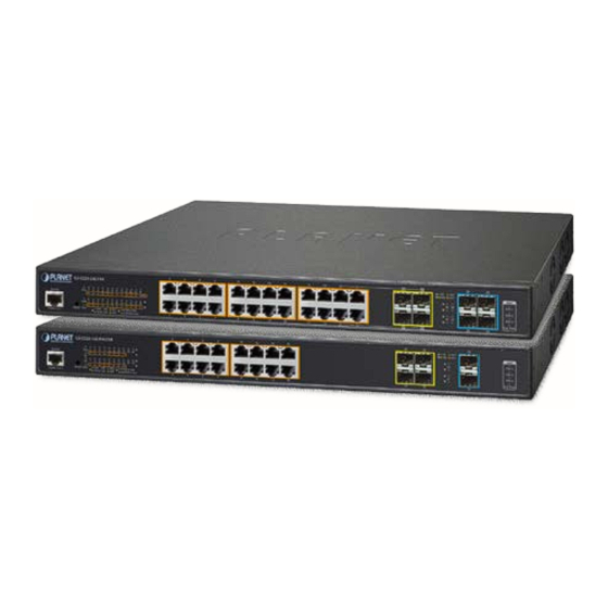
- Page 1 User’s Manual of GS-5220 PoE Series Managed Switch L3 Gigabit/10 Gigabit Managed PoE Switch GS-5220 PoE Switch Series...
- Page 2 PLANET is a registered trademark of PLANET Technology Corp. All other trademarks belong to their respective owners. Disclaimer PLANET Technology does not warrant that the hardware will work properly in all environments and applications, and makes no warranty and representation, either implied or expressed, with respect to the quality, performance, merchantability, or fitness for a particular purpose.
-
Page 3: Table Of Contents
User’s Manual of GS-5220 PoE Series Managed Switch TABLE OF CONTENTS 1. INTRODUCTION ........................11 1.1 Packet Contents ............................11 1.2 Product Description ........................... 12 1.3 How to Use This Manual ..........................19 1.4 Product Features ............................20 1.5 Product Specifications ..........................24 2. - Page 4 User’s Manual of GS-5220 PoE Series Managed Switch 4.2.1.3 IP Status ..............................69 4.2.1.4 Users Configuration ........................... 70 4.2.1.5 Privilege Levels ............................73 4.2.1.6 NTP Configuration ............................. 75 4.2.1.6.1 System Time Correction Manually ......................76 4.2.1.7 Time Configuration ............................ 77 4.2.1.8 UPnP .................................
- Page 5 User’s Manual of GS-5220 PoE Series Managed Switch 4.3.1.1 Port Configuration ........................... 116 4.3.1.2 Port Statistics Overview ........................... 118 4.3.1.3 Port Statistics Details..........................119 4.3.1.4 SFP Module Information .......................... 121 4.3.1.5 Port Mirror ............................... 123 4.3.2 Link Aggregation ..............................126 4.3.2.1 Static Aggregation ...........................
- Page 6 User’s Manual of GS-5220 PoE Series Managed Switch 4.3.5.6 IGMP Snooping Status ..........................189 4.3.5.7 IGMP Group Information ......................... 191 4.3.5.8 IGMPv3 Information..........................192 4.3.6 MLD Snooping ..............................193 4.3.6.1 MLD Snooping Configuration ........................193 4.3.6.2 MLD Snooping VLAN Configuration ......................195 4.3.6.3 MLD Snooping Port Group Filtering ......................
- Page 7 User’s Manual of GS-5220 PoE Series Managed Switch 4.4 Routing ..............................248 4.4.1 IP Configuration ..............................248 4.4.2 IP Status ................................251 4.4.3 Routing Information Base ..........................252 4.4.4 OSPF ................................. 253 4.4.4.1 Global Configuration ..........................254 4.4.4.2 Network Area ............................256 4.4.4.3 Passive Interface .............................
- Page 8 User’s Manual of GS-5220 PoE Series Managed Switch 4.5.5.5 Voice VLAN OUI Table ..........................297 4.6 Security ..............................298 4.6.1 Access Security ..............................298 4.6.1.1 Access Management ..........................298 4.6.1.2 Access Management Statistics ........................ 299 4.6.1.3 SSH ................................. 300 4.6.1.4 HTTPs ..............................301 4.6.2 AAA ...................................
- Page 9 User’s Manual of GS-5220 PoE Series Managed Switch 4.7.1.1 Power over Ethernet Powered Device ..................... 370 4.7.1.2 System Configuration ..........................371 4.7.1.3 Power over Ethernet Configuration ......................372 4.7.1.4 Port Configuration ........................... 374 4.7.1.5 PoE Status .............................. 375 4.7.1.6 Port Sequential ............................377 4.7.1.7 PoE Schedule ............................
- Page 10 User’s Manual of GS-5220 PoE Series Managed Switch 5.1 Address Table ............................416 5.2 Learning ..............................416 5.3 Forwarding & Filtering ..........................416 5.4 Store-and-Forward ........................... 416 5.5 Auto-Negotiation ............................417 6. TROUBLESHOOTING ....................... 418 APPENDIX A: Networking Connection ................420 A.1 Switch's Data RJ45 Pin Assignments -- 1000Mbps, 1000BASE-T ............
-
Page 11: Introduction
User’s Manual of GS-5220 PoE Series Managed Switch 1. INTRODUCTION 1.1 Packet Contents Open the box of the Managed Switch and carefully unpack it. The box should contain the following items: The Managed PoE Switch Quick Installation Guide ... -
Page 12: Product Description
Cybersecurity Network Solution to Minimize Security Risks The new generation of GS-5220 PoE series has the cybersecurity feature to protect the switch management and enhance the security for mission-critical network without extra deployment cost and effort. The GS-5220 PoE series expands its memory and upgrades the kernel of SSH and SSL protocols to provide strong protection against advanced threats. - Page 13 PLANET has newly developed an awesome feature -- ONVIF Support -- which is specifically designed for co-operating with Video IP Surveillances. From the GS-5220 PoE Series GUI, clients just need one click to search and show all of the ONVIF devices via network application.
- Page 14 The GS-5220 PoE Series can be configured to monitor connected PD (powered device) status in real time via ping action. Once the PD stops working and responding, the GS-5220 PoE Series will resume the PoE port power and bring the PD back to work.
- Page 15 Scheduled Power Recycling The GS-5220 PoE Series allows each of the connected PoE IP cameras or PoE wireless access points to reboot at a specified time each week. Therefore, they will reduce the chance of IP camera or AP crash resulting from buffer overflow.
- Page 16 Cost-effective 10Gbps Uplink Capacity 10G Ethernet is a big leap in the evolution of Ethernet. The four 10G SFP+ slots of the GS-5220 PoE Series support dual-speed 10GBASE-SR/LR or 1000BASE-SX/LX, meaning the administrator now can flexibly choose the suitable SFP/SFP+ transceiver according to the transmission distance or the transmission speed required to extend the network efficiently.
- Page 17 Powerful Security The GS-5220 PoE Series offers a comprehensive Layer 2 to Layer 4 access control list (ACL) for enforcing security to the edge. It can be used to restrict to network access by denying packets based on source and destination IP address, TCP/UDP port number or defined typical network applications.
- Page 18 The GS-5220 PoE Series supports SNMP and it can be managed via any management software based on the standard SNMP v1 or v2 Protocol. For reducing product learning time, the GS-5220 PoE Series offers Cisco-like command via Telnet or console port and customer doesn’t need to learn new command from these switches.
-
Page 19: How To Use This Manual
User’s Manual of GS-5220 PoE Series Managed Switch 1.3 How to Use This Manual This User’s Manual is structured as follows: Section 2, INSTALLATION The section explains the functions of the Managed Switch and how to physically install the Managed Switch. -
Page 20: Product Features
User’s Manual of GS-5220 PoE Series Managed Switch 1.4 Product Features Physical Port (GS-5220-24P(L)4X(R)/GS-5220-48P(L)4X(R)) ■ 24/48 10/100/1000BASE-T Gigabit RJ45 copper ports with 24-/48-port IEEE 802.3af/at PoE+ injector ■ 4 10GBASE-SR/LR SFP+ slots, compatible with 1000BASE-SX/LX/BX SFP ■ RJ45 console interface for switch basic management and setup ... - Page 21 − 802.3ad Link Aggregation Control Protocol (LACP) − Cisco ether-channel (static trunk) − Maximum 14 trunk groups, up to 8 ports per trunk group (GS-5220-24P(L)4X(R)) − Maximum 26 trunk groups, up to 4 ports per trunk group (GS-5220-48P(L)4X(R)) − Maximum 11 trunk groups, up to 6 ports per trunk group (GS-5220-16UP4S2X(R)) −...
- Page 22 User’s Manual of GS-5220 PoE Series Managed Switch ■ Supports QoS and In/Out bandwidth control on each port ■ Traffic-policing on the switch port ■ DSCP remarking Multicast Supports IGMP snooping v1, v2 and v3 Supports MLD snooping v1 and v2 ...
- Page 23 User’s Manual of GS-5220 PoE Series Managed Switch Four RMON groups (history, statistics, alarms and events) SNMP trap for interface Link Up and Link Down notification System Log PLANET Smart Discovery Utility for deployment management Smart fan with speed control ...
-
Page 24: Product Specifications
User’s Manual of GS-5220 PoE Series Managed Switch 1.5 Product Specifications GS-5220-24P(L)4X(R) series Product GS-5220-24P4X GS-5220-24P4XR GS-5220-24PL4X GS-5220-24PL4XR Hardware Specifications Hardware Version 24 10/100/1000BASE-T RJ45 auto-MDI/MDI-X ports Copper Ports 4 100/1000BASE-X SFP interfaces, shared with Port-21 to Port-24 SFP/mini-GBIC Slots... - Page 25 User’s Manual of GS-5220 PoE Series Managed Switch Display each port’s speed duplex mode, link status, flow control status, Port Status auto-negotiation status, trunk status TX/RX/Both Port Mirroring Many-to-1 monitor 802.1Q tagged based VLAN Q-in-Q tunneling Private VLAN Edge (PVE)
- Page 26 User’s Manual of GS-5220 PoE Series Managed Switch RFC 2863 IF-MIB RFC 2933 IGMP-STD-MIB RFC 3411 SNMP-Frameworks-MIB RFC 4292 IP Forward MIB RFC 4293 IP MIB RFC 4836 MAU-MIB IEEE 802.1X PAE LLDP Standards Conformance Regulatory Compliance FCC Part 15 Class A, CE IEEE 802.3 10BASE-T...
- Page 27 User’s Manual of GS-5220 PoE Series Managed Switch GS-5220-48P(L)4X(R) series Product GS-5220-48P4X GS-5220-48P4XR GS-5220-48PL4X GS-5220-48PL4XR Hardware Specifications Hardware Version 48 10/100/1000BASE-T RJ45 auto-MDI/MDI-X ports Copper Ports 4 10GBASE-SR/LR SFP+ interfaces (Port-25 to Port-28) SFP+ Slots Compatible with 1000BASE-SX/LX/BX SFP transceiver...
- Page 28 User’s Manual of GS-5220 PoE Series Managed Switch 802.1Q tagged based VLAN Q-in-Q tunneling Private VLAN Edge (PVE) MAC-based VLAN VLAN Protocol-based VLAN Voice VLAN MVR (Multicast VLAN registration) Up to 255 VLAN groups, out of 4095 VLAN IDs IEEE 802.3ad LACP/static trunk...
- Page 29 User’s Manual of GS-5220 PoE Series Managed Switch RFC 4293 IP MIB RFC 4836 MAU-MIB IEEE 802.1X PAE LLDP Standards Conformance Regulatory Compliance FCC Part 15 Class A, CE IEEE 802.3 10BASE-T IEEE 802.3u 100BASE-TX/100BASE-FX IEEE 802.3z Gigabit SX/LX IEEE 802.3ab Gigabit 1000T IEEE 802.3ae 10Gb/s Ethernet...
- Page 30 User’s Manual of GS-5220 PoE Series Managed Switch GS-5220-16UP(L)4X(R) series Product GS-5220-16UP4S2X GS-5220-16UP4S2XR Hardware Specifications Hardware Version 16 10/100/1000BASE-T RJ45 auto-MDI/MDI-X ports Copper Ports 4 100/1000BASE-X SFP interfaces, SFP/mini-GBIC Slots Compatible with 100BASE-FX SFP transceiver 2 10GBASE-SR/LR SFP+ interfaces (Port-17 to Port-18)
- Page 31 User’s Manual of GS-5220 PoE Series Managed Switch Many-to-1 monitor 802.1Q tagged based VLAN Q-in-Q tunneling Private VLAN Edge (PVE) MAC-based VLAN VLAN Protocol-based VLAN Voice VLAN MVR (Multicast VLAN registration) Up to 255 VLAN groups, out of 4095 VLAN IDs IEEE 802.3ad LACP/static trunk...
- Page 32 User’s Manual of GS-5220 PoE Series Managed Switch RFC 4292 IP Forward MIB RFC 4293 IP MIB RFC 4836 MAU-MIB IEEE 802.1X PAE LLDP Standards Conformance Regulatory Compliance FCC Part 15 Class A, CE IEEE 802.3 10BASE-T IEEE 802.3u 100BASE-TX/100BASE-FX IEEE 802.3z Gigabit SX/LX...
- Page 33 User’s Manual of GS-5220 PoE Series Managed Switch GS-5220-24UP(L)4X(R) series Product GS-5220-24UP4X GS-5220-24UP4XR GS-5220-24UPL4X GS-5220-24UPL4XR Hardware Specifications Hardware Version 24 10/100/1000BASE-T RJ45 auto-MDI/MDI-X ports Copper Ports 4 100/1000BASE-X SFP interfaces, shared with Port-21 to Port-24 SFP/mini-GBIC Slots Compatible with 100BASE-FX SFP transceiver...
- Page 34 User’s Manual of GS-5220 PoE Series Managed Switch auto-negotiation status, trunk status TX/RX/Both Port Mirroring Many-to-1 monitor 802.1Q tagged based VLAN Q-in-Q tunneling Private VLAN Edge (PVE) MAC-based VLAN VLAN Protocol-based VLAN Voice VLAN MVR (Multicast VLAN registration) Up to 255 VLAN groups, out of 4095 VLAN IDs IEEE 802.3ad LACP/static trunk...
- Page 35 User’s Manual of GS-5220 PoE Series Managed Switch RFC 2933 IGMP-STD-MIB RFC 3411 SNMP-Frameworks-MIB RFC 4292 IP Forward MIB RFC 4293 IP MIB RFC 4836 MAU-MIB IEEE 802.1X PAE LLDP Standards Conformance Regulatory Compliance FCC Part 15 Class A, CE IEEE 802.3 10BASE-T...
-
Page 36: Installation
User’s Manual of GS-5220 PoE Series Managed Switch 2. INSTALLATION This section describes the hardware features and installation of the Managed Switch on the desktop or rack mount. For easier management and control of the Managed Switch, familiarize yourself with its display indicators, and ports. Front panel illustrations in this chapter display the unit LED indicators. - Page 37 User’s Manual of GS-5220 PoE Series Managed Switch GS-5220-48P4X Front Panel Figure 2-1-5: Front Panel of GS-5220-48P4X GS-5220-48P4XR Front Panel Figure 2-1-6: Front Panel of GS-5220-48P4XR GS-5220-48PL4X Front Panel Figure 2-1-7: Front Panel of GS-5220-48PL4X GS-5220-48PL4XR Front Panel Figure 2-1-8: Front Panel of GS-5220-48PL4XR...
- Page 38 Winterm and so on) to enter the startup screen of the device. ■ Reset button The front panel of the GS-5220 PoE Series comes with a reset button designed for rebooting the Managed Switch without turning off and on the power. The following is the summary table of reset button...
- Page 39 Default Username: admin > 5 sec: Factory Default 。 Default Password: admin 。 Default IP Address: 192.168.0.100 。 Subnet Mask: 255.255.255.0 。 Default Gateway: 192.168.0.254 The reset button of GS-5220 PoE Series is located at the front of the switch.
-
Page 40: Led Indications
User’s Manual of GS-5220 PoE Series Managed Switch 2.1.2 LED Indications The front panel LEDs indicate instant status of power and system status, Ring, port links and data activity; they help monitor and troubleshoot when needed. Figures 2-1-15 and 2-1-26 show the LED indications of the Managed Switches. - Page 41 User’s Manual of GS-5220 PoE Series Managed Switch System / Alert (GS-5220-24P4XR and GS-5220-24PL4XR) Color Function Lights to indicate that the Switch has power from AC Green Lights to indicate that the Switch has power from DC Green Lights to indicate the system is working.
- Page 42 User’s Manual of GS-5220 PoE Series Managed Switch GS-5220-48P4X(R) / GS-5220-48PL4X(R) LED Indication Figure 2-1-19: Front Panel of GS-5220-48P4X and GS-5220-48PL4X Figure 2-1-20: Front Panel of GS-5220-48PL4XR and GS-5220-48PL4XR System / Alert (GS-5220-48P4X and GS-5220-48PL4X) Color Function Lights to indicate that the Switch has power.
- Page 43 User’s Manual of GS-5220 PoE Series Managed Switch Lights: To indicate the port is providing DC in-line power Orange Off: To indicate the connected device is not a PoE Powered Device (PD) 1/10GBASE-SR/LR SFP+ Interfaces (Port-49 to Port-52) Color...
- Page 44 User’s Manual of GS-5220 PoE Series Managed Switch Ring Green Lights to indicate that the ERPS Ring has been created successfully. Lights to indicate that FAN1 is down. FAN 1 Lights to indicate that FAN2 is down. FAN 2 FAN 3 Lights to indicate that FAN3 is down.
- Page 45 User’s Manual of GS-5220 PoE Series Managed Switch GS-5220-24UP(L)4X / GS-5220-24UP(L)4XR LED Indication Figure 2-1-23: Front Panel of GS-5220-24UP4X Figure 2-1-24: Front Panel of GS-5220-24UP4XR Figure 2-1-25: Front Panel of GS-5220-24UPL4X Figure 2-1-26: Front Panel of GS-5220-24UPL4XR System / Alert (GS-5220-UP4X and GS-5220-24UPL4X)
- Page 46 User’s Manual of GS-5220 PoE Series Managed Switch 10/100/1000BASE-T Interfaces (Port-1 to Port-24) Color Function Lights: To indicate that the port is operating at 1000Mbps. Green Blinks: To indicate that the switch is actively sending or receiving data over that port.
-
Page 47: Switch Rear Panel
Managed Switch from being damaged by unregulated surge or current to the Switch or the power adapter. ■ DC Power Connector The following GS-5220 PoE series supports redundant power system (PoE not included ): GS-5220-24P4XR ... - Page 48 M3.5. Figure 2-1-23 Rear Panel of GS-5220 PoE series Redundant Power Models Before connecting the DC power cable to the input terminal block of the GS-5220 PoE series redundant Warning: power models, make sure that the power switch is in the “OFF” position and the DC power is OFF.
-
Page 49: Installing The Switch
To install your Managed Switch on a desktop or shelf, simply complete the following steps. In the installation steps below, this manual uses the GS-5220-48T4X as an example. However, the steps for PLANET GS-5220 PoE series are similar. -
Page 50: Rack Mounting
User’s Manual of GS-5220 PoE Series Managed Switch Step 5: Supply power to the Managed Switch. Connect one end of the power cable to the Managed Switch. Connect the power plug of the power cable to a standard wall outlet. -
Page 51: Installing The Sfp/Sfp+ Transceiver
Figure 2-2-4 shows.. Figure 2-2-4: Plug-in the SFP/SFP+ Transceiver Approved PLANET SFP/SFP+ Transceivers PLANET Managed Switch supports both single mode and multi-mode SFP/SFP+ transceivers. The following list of approved PLANET SFP/SFP+ transceivers is correct at the time of publication:... - Page 52 User’s Manual of GS-5220 PoE Series Managed Switch Fast Ethernet Transceiver (100BASE-X SFP) Model Speed (Mbps) Connector Interface Fiber Mode Distance Wavelength (nm) Operating Temp. MFB-FX Multi Mode 1310nm 0 ~ 60 degrees C MFB-F20 Single Mode 20km 1310nm 0 ~ 60 degrees C...
- Page 53 Managed Switch will not recognize it. Before we connect the GS-5220 PoE series to the other network device, we have to make sure both sides of the SFP transceivers are with the same media type, for example: 1000BASE-SX to 1000BASE-SX, 1000BASE-LX to 1000BASE-LX.
- Page 54 User’s Manual of GS-5220 PoE Series Managed Switch duplex LC connector type. To connect to 1000BASE-LX SFP transceiver, please use the single-mode fiber cable with one side being the male duplex LC connector type. Connecting the Fiber Cable Insert the duplex LC connector into the SFP/SFP+ transceiver.
-
Page 55: Switch Management
User’s Manual of GS-5220 PoE Series Managed Switch 3. SWITCH MANAGEMENT This chapter explains the methods that you can use to configure management access to the Managed Switch. It describes the types of management applications and the communication and management protocols that deliver data between your management device (workstation or personal computer) and the system. -
Page 56: Management Access Overview
User’s Manual of GS-5220 PoE Series Managed Switch 3.2 Management Access Overview The Managed Switch gives you the flexibility to access and manage it using any or all of the following methods: An administration console Web browser interface ... -
Page 57: Administration Console
User’s Manual of GS-5220 PoE Series Managed Switch 3.3 Administration Console The administration console is an internal, character-oriented, and command line user interface for performing system administration such as displaying statistics or changing option settings. Using this method, you can view the administration console from a terminal, personal computer, Apple Macintosh, or workstation connected to the Managed Switch's console (serial) port. -
Page 58: Web Management
User’s Manual of GS-5220 PoE Series Managed Switch You can change these settings, if desired, after you log on. This management method is often preferred because you can remain connected and monitor the system during system reboots. Also, certain error messages are sent to the serial port, regardless of the interface through which the associated action was initiated. -
Page 59: Snmp-Based Network Management
3.6 PLANET Smart Discovery Utility For easily listing the Managed Switch in your Ethernet environment, the Planet Smart Discovery Utility from user’s manual CD-ROM is an ideal solution. The following installation instructions are to guide you to running the Planet Smart Discovery Utility. - Page 60 To click the “Control Packet Force Broadcast” function, it allows you to assign a new setting value to the Web Smart Switch under a different IP subnet address. Press the “Connect to Device” button and the Web login screen appears in Figure 3-1-4. Press the “Exit” button to shut down the Planet Smart Discovery Utility.
-
Page 61: Web Configuration
User’s Manual of GS-5220 PoE Series Managed Switch 4. WEB CONFIGURATION This section introduces the configuration and functions of the Web-based management from Managed Switch. About Web-based Management The Managed Switch offers management features that allow users to manage the Managed Switch from anywhere on the network through a standard browser such as Microsoft Internet Explorer. - Page 62 User’s Manual of GS-5220 PoE Series Managed Switch When the following login screen appears, please enter the default username "admin" with password “admin” (or the username/password you have changed via console) to log in the main screen of Managed Switch. The login screen in Figure 4-1-2 appears.
-
Page 63: Main Web Page
User’s Manual of GS-5220 PoE Series Managed Switch It is recommended to use Mozilla Firefox 1.5 or above to access Managed Switch. The changed IP address takes effect immediately after clicking on the Save button. You need to use the new IP address to access the Web interface. - Page 64 User’s Manual of GS-5220 PoE Series Managed Switch Figure 4-1-5: Managed Switch Main Functions Menu...
-
Page 65: System
User’s Manual of GS-5220 PoE Series Managed Switch 4.2 System Use the System menu items to display and configure basic administrative details of the Managed Switch. Under the System, the following topics are provided to configure and view the system information. This section has the following items: ■... -
Page 66: Management
User’s Manual of GS-5220 PoE Series Managed Switch 4.2.1 Management 4.2.1.1 System Information The System Information page provides information for the current device information. System Information page helps a switch administrator to identify the hardware MAC address, software version and system uptime. The screen in Figure 4-2-1 appears. -
Page 67: Ip Configuration
User’s Manual of GS-5220 PoE Series Managed Switch 4.2.1.2 IP Configuration The IP Configuration includes the IP Configuration, IP Interface and IP Routes. The configured column is used to view or change the IP configuration. The maximum number of interfaces supported is 128 and the maximum number of routes is 128. - Page 68 User’s Manual of GS-5220 PoE Series Managed Switch When DNS proxy is enabled, system will relay DNS requests to the DNS Proxy currently configured DNS server, and reply as a DNS resolver to the client devices on the network. •...
-
Page 69: Ip Status
User’s Manual of GS-5220 PoE Series Managed Switch Buttons : Click to add a new IP interface. A maximum of 128 interfaces are supported. : Click to add a new IP route. A maximum of 32 routes are supported. : Click to apply changes. -
Page 70: Users Configuration
User’s Manual of GS-5220 PoE Series Managed Switch • Neighbor Cache IP Address The IP address of the entry. Link Address The Link (MAC) address for which a binding to the IP address given exists. Buttons Auto-refresh : Check this box to refresh the page automatically. Automatic refresh occurs every 3 seconds. - Page 71 User’s Manual of GS-5220 PoE Series Managed Switch Add / Edit User This page configures a user – add, edit or delete user. Figure 4-2-1-5: Add / Edit User Configuration Page Screenshot The page includes the following fields: Object Description •...
- Page 72 User’s Manual of GS-5220 PoE Series Managed Switch Once the new user is added, the new user entry is shown on the Users Configuration page. Figure 4-2-1-6: User Configuration Page Screenshot If you forget the new password after changing the default password, please press the “Reset”...
-
Page 73: Privilege Levels
User’s Manual of GS-5220 PoE Series Managed Switch 4.2.1.5 Privilege Levels This page provides an overview of the privilege levels. After setup is completed, please press the “Apply” button to take effect. Please login web interface with new user name and password and the screen in Figure 4-2-1-7 appears. - Page 74 User’s Manual of GS-5220 PoE Series Managed Switch Security: Authentication, System Access Management, Port (contains Dot1x port, MAC based and the MAC Address Limit), ACL, HTTPS, SSH, ARP Inspection and IP source guard. IP: Everything except 'ping'. ...
-
Page 75: Ntp Configuration
User’s Manual of GS-5220 PoE Series Managed Switch 4.2.1.6 NTP Configuration Configure NTP on this page. NTP is an acronym for Network Time Protocol, a network protocol for synchronizing the clocks of computer systems. NTP uses UDP (data grams) as transport layer. You can specify NTP Servers. The NTP Configuration... -
Page 76: System Time Correction Manually
User’s Manual of GS-5220 PoE Series Managed Switch 4.2.1.6.1 System Time Correction Manually Configure NTP on this page. NTP is an acronym for Network Time Protocol, a network protocol for synchronizing the clocks of computer systems. NTP uses UDP (data grams) as transport layer. You can specify NTP Servers. The NTP Configuration... -
Page 77: Time Configuration
User’s Manual of GS-5220 PoE Series Managed Switch 4.2.1.7 Time Configuration Configure Time Zone on this page. A Time Zone is a region that has a uniform standard time for legal, commercial, and social purposes. It is convenient for areas in close commercial or other communication to keep the same time, so time zones tend to follow the boundaries of countries and their subdivisions. -
Page 78: Upnp
User’s Manual of GS-5220 PoE Series Managed Switch 'Non-Recurring' and configure the Daylight Saving Time duration for single time configuration. ( Default: Disabled ). • • Week - Select the starting week number. Start Time Settings • Day - Select the starting day. - Page 79 User’s Manual of GS-5220 PoE Series Managed Switch The page includes the following fields: Object Description • Mode Indicates the UPnP operation mode. Possible modes are: Enabled: Enable UPnP mode operation. Disabled: Disable UPnP mode operation. When the mode is enabled, two ACEs are added automatically to trap UPnP related packets to CPU.
-
Page 80: Dhcp Relay
User’s Manual of GS-5220 PoE Series Managed Switch 4.2.1.9 DHCP Relay Configure DHCP Relay on this page. DHCP Relay is used to forward and transfer DHCP messages between the clients and the server when they are not on the same subnet domain. -
Page 81: Dhcp Relay Statistics
User’s Manual of GS-5220 PoE Series Managed Switch Mode are: Enabled: Enable DHCP relay information mode operation. When enabling DHCP relay information mode operation, the agent inserts specific information (option82) into a DHCP message when forwarding to DHCP server and removing it from a DHCP message when transferring to DHCP client. - Page 82 User’s Manual of GS-5220 PoE Series Managed Switch Server Statistics Object Description • Transmit to Server The packet number that relayed from client to server. • Transmit Error The packet number that erroneously sent packets to clients. • Receive from Server The packet number that received packets from server.
-
Page 83: Cpu Load
User’s Manual of GS-5220 PoE Series Managed Switch 4.2.1.11 CPU Load This page displays the CPU load, using an SVG graph. The load is measured as average over the last 100ms, 1 sec and 10 seconds intervals. The last 120 samples are graphed, and the last numbers are displayed as text as well. In order to display the SVG graph, your browser must support the SVG format. -
Page 84: System Log
User’s Manual of GS-5220 PoE Series Managed Switch 4.2.1.12 System Log The Managed Switch system log information is provided here. The System Log screen in Figure 4-2-1-15 appears. Figure 4-2-1-15: System Log Page Screenshot The page includes the following fields:... -
Page 85: Detailed Log
User’s Manual of GS-5220 PoE Series Managed Switch : Updates the system log entries, ending at the last entry currently displayed. : Updates the system log entries, starting from the last entry currently displayed. : Updates the system log entries, ending at the last available entry ID. -
Page 86: Remote Syslog
User’s Manual of GS-5220 PoE Series Managed Switch 4.2.1.14 Remote Syslog Configure remote syslog on this page. The Remote Syslog screen in Figure 4-2-1-17 appears. Figure 4-2-1-17: Remote Syslog Page Screenshot The page includes the following fields: Object Description • Mode Indicates the server mode operation. -
Page 87: Smtp Configuration
User’s Manual of GS-5220 PoE Series Managed Switch 4.2.1.15 SMTP Configuration This page facilitates an SMTP Configuration on the switch. The SMTP Configure screen in Figure 4-2-1-18 appears. Figure 4-2-1-18: SMTP Configuration Page Screenshot The page includes the following fields:... -
Page 88: Simple Network Management Protocol
User’s Manual of GS-5220 PoE Series Managed Switch 4.2.2 Simple Network Management Protocol 4.2.2.1 SNMP Overview The Simple Network Management Protocol (SNMP) is an application layer protocol that facilitates the exchange of management information between network devices. It is part of the Transmission Control Protocol/Internet Protocol (TCP/IP) protocol suite. -
Page 89: Snmp System Configuration
User’s Manual of GS-5220 PoE Series Managed Switch SNMP community. It will not respond to requests from management stations that do not belong to one of its communities. SNMP default communities are: 。 Write = private 。 Read = public Use the SNMP Menu to display or configure the Managed Switch's SNMP function. - Page 90 User’s Manual of GS-5220 PoE Series Managed Switch • Indicates the community read access string to permit access to SNMP agent. Read Community The allowed string length is 0 to 255, and the allowed content is the ASCII characters from 33 to 126.
-
Page 91: Snmp Trap Configuration
User’s Manual of GS-5220 PoE Series Managed Switch 4.2.2.3 SNMP Trap Configuration Configure SNMP trap on this page. The SNMP Trap Configuration screen in Figure 4-2-2-3 appears. Figure 4-2-2-3: SNMP Trap Configuration Page Screenshot The page includes the following fields:... - Page 92 User’s Manual of GS-5220 PoE Series Managed Switch SNMP v2c: Set SNMP trap supported version 2c. SNMP v3: Set SNMP trap supported version 3. • Trap Community Indicates the community access string when send SNMP trap packet. The allowed string length is 0 to 255, and the allowed content is the ASCII characters from 33 to 126.
-
Page 93: Snmp System Information
User’s Manual of GS-5220 PoE Series Managed Switch RMON: Enable/disable RMON trap. Buttons : Click to apply changes : Click to undo any changes made locally and revert to previously saved values. 4.2.2.4 SNMP System Information The switch system information is provided here. The SNMP System Information screen in Figure 4-2-2-4 appears. -
Page 94: Snmpv3 Communities
User’s Manual of GS-5220 PoE Series Managed Switch 4.2.2.5 SNMPv3 Communities Configure SNMPv3 communities table on this page. The entry index key is Community. The SNMPv3 Communities screen in Figure 4-2-2-5 appears. Figure 4-2-2-5: SNMPv3 Communities Configuration Page Screenshot The page includes the following fields:... -
Page 95: Snmpv3 Users
User’s Manual of GS-5220 PoE Series Managed Switch 4.2.2.6 SNMPv3 Users Configure SNMPv3 users table on this page. The entry index keys are Engine ID and User Name. The SNMPv3 Users screen Figure 4-2-2-6 appears. Figure 4-2-2-6: SNMPv3 Users Configuration Page Screenshot... - Page 96 User’s Manual of GS-5220 PoE Series Managed Switch protocol. SHA: An optional flag to indicate that this user using SHA authentication protocol. The value of security level cannot be modified if entry already exist. That means must first ensure that the value is set correctly.
-
Page 97: Snmpv3 Groups
User’s Manual of GS-5220 PoE Series Managed Switch 4.2.2.7 SNMPv3 Groups Configure SNMPv3 groups table on this page. The entry index keys are Security Model and Security Name. The SNMPv3 Groups screen in Figure 4-2-2-7 appears. Figure 4-2-2-7: SNMPv3 Groups Configuration Page Screenshot... -
Page 98: Snmpv3 Views
User’s Manual of GS-5220 PoE Series Managed Switch 4.2.2.8 SNMPv3 Views Configure SNMPv3 views table on this page. The entry index keys are View Name and OID Subtree. The SNMPv3 Views screen in Figure 4-2-2-8 appears. Figure 4-2-2-8: SNMPv3 Views Configuration Page Screenshot... -
Page 99: Snmpv3 Access
User’s Manual of GS-5220 PoE Series Managed Switch 4.2.2.9 SNMPv3 Access Configure SNMPv3 accesses table on this page. The entry index keys are Group Name, Security Model and Security Level. The SNMPv3 Access screen in Figure 4-2-2-9 appears. Figure 4-2-2-9: SNMPv3 Accesses Configuration Page Screenshot... -
Page 100: Rmon
User’s Manual of GS-5220 PoE Series Managed Switch : Click to apply changes : Click to undo any changes made locally and revert to previously saved values. 4.2.3 RMON RMON is the most important expansion of the standard SNMP. RMON is a set of MIB definitions, used to define standard network monitor functions and interfaces, enabling the communication between SNMP management terminals and remote monitors. - Page 101 User’s Manual of GS-5220 PoE Series Managed Switch falling threshold. The range is from 1 to 2^31-1. • Variable Indicates the particular variable to be sampled; the possible variables are: InOctets: The total number of octets received on the interface, including framing characters.
- Page 102 User’s Manual of GS-5220 PoE Series Managed Switch Buttons : Click to add a new community entry. : Click to apply changes Click to undo any changes made locally and revert to previously saved values.
-
Page 103: Rmon Alarm Status
User’s Manual of GS-5220 PoE Series Managed Switch 4.2.3.2 RMON Alarm Status This page provides an overview of RMON Alarm entries. Each page shows up to 99 entries from the Alarm table, default being 20, selected through the "entries per page" input field. When first visited, the web page will show the first 20 entries from the beginning of the Alarm table. -
Page 104: Rmon Event Configuration
User’s Manual of GS-5220 PoE Series Managed Switch 4.2.3.3 RMON Event Configuration Configure RMON Event table on this page. The entry index key is ID; screen in Figure 4-2-3-3 appears. Figure 4-2-3-3 RMON Event Configuration Page Screenshot The page includes the following fields:... -
Page 105: Rmon Event Status
User’s Manual of GS-5220 PoE Series Managed Switch 4.2.3.4 RMON Event Status This page provides an overview of RMON Event table entries. Each page shows up to 99 entries from the Event table, default being 20, selected through the "entries per page" input field. When first visited, the web page will show the first 20 entries from the beginning of the Event table. -
Page 106: Rmon History Configuration
User’s Manual of GS-5220 PoE Series Managed Switch 4.2.3.5 RMON History Configuration Configure RMON History table on this page. The entry index key is ID; screen in Figure 4-2-3-5 appears. Figure 4-2-3-5: RMON History Configuration Page Screenshot The page includes the following fields:... -
Page 107: Rmon History Status
User’s Manual of GS-5220 PoE Series Managed Switch 4.2.3.6 RMON History Status This page provides an detail of RMON history entries; screen in Figure 4-2-3-6 appears. Figure 4-2-3-6: RMON History Overview Page Screenshot The page includes the following fields: Object Description •... -
Page 108: Rmon Statistics Configuration
User’s Manual of GS-5220 PoE Series Managed Switch Buttons : Click to refresh the page immediately. Auto-refresh Check this box to refresh the page automatically. Automatic refresh occurs every 3 seconds. Updates the table, starting from the first entry in the History table, i.e., the entry with the lowest History Index and Sample Index : Updates the table, starting with the entry after the last entry currently displayed. -
Page 109: Rmon Statistics Status
User’s Manual of GS-5220 PoE Series Managed Switch 4.2.3.8 RMON Statistics Status This page provides an overview of RMON Statistics entries. Each page shows up to 99 entries from the Statistics table, default being 20, selected through the "entries per page" input field. When first visited, the web page will show the first 20 entries from the beginning of the Statistics table. - Page 110 User’s Manual of GS-5220 PoE Series Managed Switch • 64 Bytes The total number of packets (including bad packets) received that were 64 octets in length. • 65~127 The total number of packets (including bad packets) received that were between 65 to 127 octets in length.
-
Page 111: Dhcp Server
User’s Manual of GS-5220 PoE Series Managed Switch 4.2.4 DHCP server 4.2.4.1 DHCP Server Mode Configuration Configure DHCP server mode on this page. The entry index key is ID.; screen in Figure 4-2-4-1 appears. Figure 4-2-4-1: DHCP server mode Page Screenshot... -
Page 112: Dhcp Server Excluded Ip Configuration
User’s Manual of GS-5220 PoE Series Managed Switch Disabled: Disable DHCP server pre VLAN. Buttons : Click to add a new VLAN range. : Click to apply changes Click to undo any changes made locally and revert to previously saved values. -
Page 113: Dhcp Server Pool Configuration
User’s Manual of GS-5220 PoE Series Managed Switch 4.2.4.3 DHCP Server pool Configuration This page manages DHCP pools. According to the DHCP pool, DHCP server will allocate IP address and deliver configuration parameters to DHCP client. screen in Figure 4-2-4-3 appears. -
Page 114: Dhcp Server Pool Configuration
User’s Manual of GS-5220 PoE Series Managed Switch 4.2.4.4 DHCP Server pool Configuration This page displays the database counters and the number of DHCP messages sent and received by DHCP server. screen in Figure 4-2-4-4 appears. Figure 4-2-4-4: DHCP server Statistics Page Screenshot... - Page 115 User’s Manual of GS-5220 PoE Series Managed Switch DHCP message Received Counters Object Description • Discover Number of DHCP DISCOVER messages received. • Request Number of DHCP REQUEST messages received. • Decline Number of DHCP DECLINE messages received. • Release Number of DHCP RELEASE messages received.
-
Page 116: Switching
User’s Manual of GS-5220 PoE Series Managed Switch 4.3 Switching 4.3.1 Port Management Use the Port Menu to display or configure the Managed Switch's ports. This section has the following items: Port Configuration Configures port connection settings Port Statistics Overview Lists Ethernet and RMON port statistics ... - Page 117 User’s Manual of GS-5220 PoE Series Managed Switch • Select any available link speed for the given switch port. Draw the menu bar to Configured Link Speed select the mode. Copper interface: Auto – It is default mode. Set up Auto negotiation.
-
Page 118: Port Statistics Overview
User’s Manual of GS-5220 PoE Series Managed Switch 4.3.1.2 Port Statistics Overview This page provides an overview of general traffic statistics for all switch ports. The Port Statistics Overview screen in Figure 4-3-1-2 appears. Figure 4-3-1-2: Port Statistics Overview Page Screenshot... -
Page 119: Port Statistics Details
User’s Manual of GS-5220 PoE Series Managed Switch 4.3.1.3 Port Statistics Details This page provides detailed traffic statistics for a specific switch port. Use the port select box to select which switch port details to display. The displayed counters are the totals for receive and transmit, the size counters for receive and transmit, and the error counters for receive and transmit. - Page 120 User’s Manual of GS-5220 PoE Series Managed Switch The number of received and transmitted (good and bad) packets split into categories based on their respective frame sizes. Receive and Transmit Queue Counters The number of received and transmitted packets per input and output queue.
-
Page 121: Sfp Module Information
User’s Manual of GS-5220 PoE Series Managed Switch 4.3.1.4 SFP Module Information The WGSW-48040HP has supported the SFP module with digital diagnostics monitoring (DDM) function. This feature is also known as digital optical monitoring (DOM). You can check the physical or operational status of an SFP module via the SFP Module Information page. - Page 122 User’s Manual of GS-5220 PoE Series Managed Switch • TX power (dBm) Display the TX power of current SFP DDM module; the TX power value is got – SFP DDM Module Only from the SFP DDM module. • RX power (dBm) Display the RX power of current SFP DDM module;...
-
Page 123: Port Mirror
User’s Manual of GS-5220 PoE Series Managed Switch 4.3.1.5 Port Mirror Configure port Mirroring on this page. This function provides monitoring network traffic that forwards a copy of each incoming or outgoing packet from one port of a network Switch to another port where the packet can be studied. It enables the manager to keep close track of switch performance and alter it if necessary. - Page 124 User’s Manual of GS-5220 PoE Series Managed Switch Figure 4-3-1-7: Mirror Configuration Page Screenshot The page includes the following fields: Object Description • Session Select session id to configure. • To Enabled/Disabled the mirror or Remote Mirroring function Mode • Type Mirror The switch is running on mirror mode.
- Page 125 User’s Manual of GS-5220 PoE Series Managed Switch If you shut down the port which is a reflector port, the remote mirror function cannot work • Source VLAN(s) The switch can supports VLAN-based Mirroring. If you want to monitor some VLANs on Configuration the switch, you can set the selected VLANs on this field.
-
Page 126: Link Aggregation
User’s Manual of GS-5220 PoE Series Managed Switch 4.3.2 Link Aggregation Port Aggregation optimizes port usage by linking a group of ports together to form a single Link Aggregated Groups (LAGs). Port Aggregation multiplies the bandwidth between the devices, increases port flexibility, and provides link redundancy. - Page 127 User’s Manual of GS-5220 PoE Series Managed Switch The Link Aggregation Control Protocol (LACP) provides a standardized means for exchanging information between Partner Systems that require high speed redundant links. Link aggregation lets you group up to eight consecutive ports into a single dedicated connection.
-
Page 128: Static Aggregation
User’s Manual of GS-5220 PoE Series Managed Switch 4.3.2.1 Static Aggregation This page is used to configure the Aggregation hash mode and the aggregation group. The aggregation hash mode settings are global. Hash Code Contributors The Static Aggregation screen in Figure 4-3-2-1 appears. - Page 129 User’s Manual of GS-5220 PoE Series Managed Switch Figure 4-3-2-2: Aggregation Group Configuration Page Screenshot The page includes the following fields: .Object Description • Indicates the group ID for the settings contained in the same row. Group ID Group ID "Normal"...
-
Page 130: Lacp Configuration
User’s Manual of GS-5220 PoE Series Managed Switch 4.3.2.2 LACP Configuration Link Aggregation Control Protocol (LACP) - LACP LAG negotiate Aggregated Port links with other LACP ports located on a different device. LACP allows switches connected to each other to discover automatically whether any ports are member of the same LAG. -
Page 131: Lacp System Status
User’s Manual of GS-5220 PoE Series Managed Switch • The Priority controls the priority of the port. If the LACP partner wants to form a Priority larger group than is supported by this device then this parameter will control which ports will be active and which ports will be in a backup role. Lower number means greater priority. -
Page 132: Lacp Port Status
User’s Manual of GS-5220 PoE Series Managed Switch 4.3.2.4 LACP Port Status This page provides a status overview of LACP status for all ports. The LACP Port Status screen in Figure 4-5-6 appears. Figure 4-3-2-4: LACP Status Page Screenshot The page includes the following fields:... -
Page 133: Vlan
User’s Manual of GS-5220 PoE Series Managed Switch 4.3.3 VLAN 4.3.3.1 VLAN Overview A Virtual Local Area Network (VLAN) is a network topology configured according to a logical scheme rather than the physical layout. VLAN can be used to combine any collection of LAN segments into an autonomous user group that appears as a single LAN. -
Page 134: Ieee 802.1Q Vlan
User’s Manual of GS-5220 PoE Series Managed Switch 4.3.3.2 IEEE 802.1Q VLAN In large networks, routers are used to isolate broadcast traffic for each subnet into separate domains. This Managed Switch provides a similar service at Layer 2 by using VLANs to organize any group of network nodes into separate broadcast domains. - Page 135 User’s Manual of GS-5220 PoE Series Managed Switch ■ 802.1Q VLAN Tags The figure below shows the 802.1Q VLAN tag. There are four additional octets inserted after the source MAC address. Their presence is indicated by a value of 0x8100 in the Ether Type field. When a packet's Ether Type field is equal to 0x8100, the packet carries the IEEE 802.1Q/802.1p tag.
- Page 136 User’s Manual of GS-5220 PoE Series Managed Switch Every physical port on a switch has a PVID. 802.1Q ports are also assigned a PVID, for use within the switch. If no VLAN are defined on the switch, all ports are then assigned to a default VLAN with a PVID equal to 1. Untagged packets are assigned the PVID of the port on which they were received.
-
Page 137: Vlan Port Configuration
User’s Manual of GS-5220 PoE Series Managed Switch ■ Port Overlapping Port overlapping can be used to allow access to commonly shared network resources among different VLAN groups, such as file servers or printers. Note that if you implement VLANs which do not overlap, but still need to communicate, you can connect them by enabled routing on this switch. - Page 138 User’s Manual of GS-5220 PoE Series Managed Switch ■ IEEE 802.1Q Tunneling (Q-in-Q) IEEE 802.1Q Tunneling (Q-in-Q) is designed for service providers carrying traffic for multiple customers across their networks. Q-in-Q tunneling is used to maintain customer-specific VLAN and Layer 2 protocol configurations even when different customers use the same internal VLAN IDs.
- Page 139 User’s Manual of GS-5220 PoE Series Managed Switch Global VLAN Configuration The Global VLAN Configuration screen in Figure 4-6-1 appears. Figure 4-6-1 : Global VLAN Configuration Screenshot The page includes the following fields: Object Description • This field shows the allowed Access VLANs, it only affects ports configured as...
- Page 140 User’s Manual of GS-5220 PoE Series Managed Switch The page includes the following fields: Object Description • Port This is the logical port number for this row. • Mode Access Access ports are normally used to connect to end stations. Dynamic features like Voice VLAN may add the port to more VLANs behind the scenes.
- Page 141 User’s Manual of GS-5220 PoE Series Managed Switch The Port VLAN is called an "Access VLAN" for ports in Access mode and Native VLAN for ports in Trunk or Hybrid mode. • Port Type Ports in hybrid mode allow for changing the port type, that is, whether a frame's VLAN tag is used to classify the frame on ingress to a particular VLAN, and if so, which TPID it reacts on.
- Page 142 User’s Manual of GS-5220 PoE Series Managed Switch Only untagged frames are accepted on ingress. Tagged frames are discarded. Egress Tagging This option is only available for ports in Hybrid mode. Ports in Trunk and Hybrid mode may control the tagging of frames on egress.
-
Page 143: Vlan Membership Status
User’s Manual of GS-5220 PoE Series Managed Switch 4.3.3.4 VLAN Membership Status This page provides an overview of membership status for VLAN users. The VLAN Membership Status screen in Figure 4-6-4 appears. Figure 4-3-3-4: VLAN Membership Status for Static User Page Screenshot... -
Page 144: Vlan Port Status
User’s Manual of GS-5220 PoE Series Managed Switch information for all the VLAN Users, and this is by default. VLAN membership allows the frames classified to the VLAN ID to be forwarded on the respective VLAN member ports. Buttons : Select VLAN Users from this drop down list. - Page 145 User’s Manual of GS-5220 PoE Series Managed Switch tags are not removed. • Ingress Filtering Show the ingress filtering for a port. This parameter affects VLAN ingress processing. If ingress filtering is enabled and the ingress port is not a member of the classified VLAN of the frame, the frame is discarded.
-
Page 146: Private Vlan
User’s Manual of GS-5220 PoE Series Managed Switch 4.3.3.6 Private VLAN The Private VLAN membership configurations for the switch can be monitored and modified here. Private VLANs can be added or deleted here. Port members of each Private VLAN can be added or removed here. -
Page 147: Port Isolation
User’s Manual of GS-5220 PoE Series Managed Switch The “Delete” button can be used to undo the addition of new Private VLANs. Buttons : Click to add new VLAN. : Click to save changes. : Click to undo any changes made locally and revert to previously saved values. - Page 148 User’s Manual of GS-5220 PoE Series Managed Switch For private VLANs to be applied, the switch must first be configured for standard VLAN operation When this is in place, one or more of the configured VLANs can be configured as private VLANs. Ports in a private VLAN fall into one of these two groups: ...
-
Page 149: Vlan Setting Example
User’s Manual of GS-5220 PoE Series Managed Switch 4.3.3.8 VLAN setting example: Separate VLAN 802.1Q VLAN Trunk Port Isolate 4.3.3.8.1 Two Separate 802.1Q VLANs The diagram shows how the Managed Switch handle Tagged and Untagged traffic flow for two VLANs. VLAN Group 2 and VLAN Group 3 are separated VLAN. - Page 150 User’s Manual of GS-5220 PoE Series Managed Switch [PC-4],[PC-5] and [PC-6] received no packet. While the packet leaves Port-2, it will be stripped away it tag becoming an untagged packet. While the packet leaves Port-3, it will keep as a tagged packet with VLAN Tag=2.
- Page 151 User’s Manual of GS-5220 PoE Series Managed Switch Figure 4-3-3-10: Change Port VLAN of Port 1~3 to be VLAN2 and Port VLAN of Port 4~6 to be VLAN3 Enable VLAN Tag for specific ports Link Type: Port-3 (VLAN-2) and Port-6 (VLAN-3) Change Port 3 Mode as Trunk, Selects Egress Tagging as Tag All and Types 2 in the Allowed VLANs column.
-
Page 152: Vlan Trunking Between Two 802.1Q Aware Switches
User’s Manual of GS-5220 PoE Series Managed Switch 4.3.3.8.2 VLAN Trunking between two 802.1Q aware switches The most cases are used for “Uplink” to other switches. VLANs are separated at different switches, but they need to access with other switches within the same VLAN group. The screen in Figure 4-3-3-12 appears. - Page 153 User’s Manual of GS-5220 PoE Series Managed Switch Figure 4-3-3-14: Changes Port VLAN of Port 1~3 to be VLAN2 and Port VLAN of Port 4~6 to be VLAN3 For the VLAN ports connecting to the hosts, please refer to 4.6.10.1 examples. The following steps will focus on the VLAN Trunk port configuration.
-
Page 154: Port Isolate
User’s Manual of GS-5220 PoE Series Managed Switch 4.3.3.8.3 Port Isolate The diagram shows how the Managed Switch handles isolated and promiscuous ports, and the each PC is not able to access the isolated port of each other’s PCs. But they all need to access with the same server/AP/Printer. This section will show you how to configure the port for the server –... -
Page 155: Mac-Based Vlan
User’s Manual of GS-5220 PoE Series Managed Switch 4.3.3.9 MAC-based VLAN The MAC-based VLAN entries can be configured here. This page allows for adding and deleting MAC-based VLAN entries and assigning the entries to different ports. This page shows only static entries. The MAC-based VLAN screen in Figure 4-3-3-17 appears. -
Page 156: Protocol-Based Vlan
User’s Manual of GS-5220 PoE Series Managed Switch : Click to undo any changes made locally and revert to previously saved values. Auto-refresh : Check this box to refresh the page automatically. Automatic refresh occurs every 3 seconds. : Click to refresh the page immediately. - Page 157 User’s Manual of GS-5220 PoE Series Managed Switch 0x0600-0xffff For LLC: Valid value in this case is comprised of two different sub-values. a. DSAP: 1-byte long string (0x00-0xff) b. SSAP: 1-byte long string (0x00-0xff) For SNAP: Valid value in this case also is comprised of two different sub-values.
-
Page 158: Protocol-Based Vlan Membership
User’s Manual of GS-5220 PoE Series Managed Switch 4.3.3.11 Protocol-based VLAN Membership This page allows you to map a already configured Group Name to a VLAN for the switch. The Group Name to VLAN Mapping Table screen in Figure 4-3-3-19 appears. -
Page 159: Spanning Tree Protocol
User’s Manual of GS-5220 PoE Series Managed Switch 4.3.4 Spanning Tree Protocol 4.3.4.1 Theory The Spanning Tree protocol can be used to detect and disable network loops, and to provide backup links between switches, bridges or routers. This allows the switch to interact with other bridging devices in your network to ensure that only one route exists between any two stations on the network, and provide backup links which automatically take over when a primary link goes down. - Page 160 User’s Manual of GS-5220 PoE Series Managed Switch The port identifier of the transmitting port The switch sends BPDUs to communicate and construct the spanning-tree topology. All switches connected to the LAN on which the packet is transmitted will receive the BPDU. BPDUs are not directly forwarded by the switch, but the receiving switch uses the information in the frame to calculate a BPDU, and, if the topology changes, initiates a BPDU transmission.
- Page 161 User’s Manual of GS-5220 PoE Series Managed Switch From disabled to blocking Figure 4-3-4-1: STP Port State Transitions You can modify each port state by using management software. When you enable STP, every port on every switch in the network goes through the blocking state and then transitions through the states of listening and learning at power up.
- Page 162 User’s Manual of GS-5220 PoE Series Managed Switch The following are the user-configurable STP parameters for the switch level: Parameter Description Default Value Bridge Identifier(Not user A combination of the User-set priority and 32768 + MAC configurable the switch’s MAC address.
- Page 163 User’s Manual of GS-5220 PoE Series Managed Switch Bridge Priority 32,768 User-Changeable STA Parameters The Switch’s factory default setting should cover the majority of installations. However, it is advisable to keep the default settings as set at the factory; unless, it is absolutely necessary. The user changeable parameters in the Switch are as follows: Priority –...
- Page 164 User’s Manual of GS-5220 PoE Series Managed Switch and Port Cost settings is, however, relatively straight forward. Figure 4-3-4-2: Before Applying the STA Rules In this example, only the default STP values are used. Figure 4-3-4-3: After Applying the STA Rules...
- Page 165 User’s Manual of GS-5220 PoE Series Managed Switch The switch with the lowest Bridge ID (switch C) was elected the root bridge, and the ports were selected to give a high port cost between switches B and C. The two (optional) Gigabit ports (default port cost = 20,000) on switch A are connected to one (optional) Gigabit port on both switch B and C.
-
Page 166: Stp System Configuration
User’s Manual of GS-5220 PoE Series Managed Switch 4.3.4.2 STP System Configuration This page allows you to configure STP system settings. The settings are used by all STP Bridge instances in the Switch. The Managed Switch support the following Spanning Tree protocols: ‧... - Page 167 User’s Manual of GS-5220 PoE Series Managed Switch RSTP (IEEE 802.2w Rapid Spanning Tree Protocol) MSTP (IEEE 802.1s Multiple Spanning Tree Protocol) • Bridge Priority Controls the bridge priority. Lower numeric values have better priority. The bridge priority plus the MSTI instance number, concatenated with the 6-byte MAC address of the switch forms a Bridge Identifier.
-
Page 168: Bridge Status
User’s Manual of GS-5220 PoE Series Managed Switch Timeout enabled. Valid values are between 30 and 86400 seconds (24 hours). The Managed Switch implements the Rapid Spanning Protocol as the default spanning tree protocol. When selecting “Compatibles” mode, the system uses the RSTP (802.1w) to be compatible and to co-work with another STP (802.1D)’s BPDU control packet. -
Page 169: Cist Port Configuration
User’s Manual of GS-5220 PoE Series Managed Switch Auto-refresh : Check this box to refresh the page automatically. Automatic refresh occurs every 3 seconds. : Click to refresh the page immediately. 4.3.4.4 CIST Port Configuration This page allows the user to inspect the current STP CIST port configurations, and possibly change them as well. The CIST... - Page 170 User’s Manual of GS-5220 PoE Series Managed Switch • Controls the port priority. This can be used to control priority of ports having Priority identical port cost. (See above). Default: 128 Range: 0-240, in steps of 16 • AdminEdge Controls whether the operEdge flag should start as being set or cleared. (The initial operEdge state when a port is initialized).
- Page 171 User’s Manual of GS-5220 PoE Series Managed Switch By default, the system automatically detects the speed and duplex mode used on each port, and configures the path cost according to the values shown below. Path cost “0” is used to indicate auto-configuration mode. When the short path cost method is selected and the default path cost recommended by the IEEE 8021w standard exceeds 65,535, the default is set to 65,535.
-
Page 172: Msti Priorities
User’s Manual of GS-5220 PoE Series Managed Switch 4.3.4.5 MSTI Priorities This page allows the user to inspect the current STP MSTI bridge instance priority configurations, and possibly change them as well. The MSTI Priority screen in Figure 4-3-4-7 appears. -
Page 173: Msti Configuration
User’s Manual of GS-5220 PoE Series Managed Switch 4.3.4.6 MSTI Configuration This page allows the user to inspect the current STP MSTI bridge instance priority configurations, and possibly change them as well. The MSTI Configuration screen in Figure 4-3-4-8 appears. -
Page 174: Msti Ports Configuration
User’s Manual of GS-5220 PoE Series Managed Switch MSTI Mapping Object Description • MSTI The bridge instance. The CIST is not available for explicit mapping, as it will receive the VLANs not explicitly mapped. • VLANs Mapped The list of VLAN's mapped to the MSTI. The VLANs must be separated with comma and/or space. - Page 175 User’s Manual of GS-5220 PoE Series Managed Switch Figure 4-3-4-10 : MST1 MSTI Port Configuration Page Screenshot The page includes the following fields: MSTx MSTI Port Configuration Object Description • Port The switch port number of the corresponding STP CIST (and MSTI) port.
-
Page 176: Port Status
User’s Manual of GS-5220 PoE Series Managed Switch 4.3.4.8 Port Status This page displays the STP CIST port status for port physical ports in the currently selected switch. The STP Port Status screen in Figure 4-3-4-11 appears. Figure 4-3-4-11: STP Port Status Page Screenshot... -
Page 177: Port Statistics
User’s Manual of GS-5220 PoE Series Managed Switch 4.3.4.9 Port Statistics This page displays the STP port statistics counters for port physical ports in the currently selected switch. The STP Port Statistics screen in Figure 4-3-4-12 appears. Figure 4-3-4-12: STP Statistics Page Screenshot... -
Page 178: Igmp Snooping
User’s Manual of GS-5220 PoE Series Managed Switch 4.3.5 IGMP Snooping The Internet Group Management Protocol (IGMP) lets host and routers share information about multicast groups memberships. IGMP snooping is a switch feature that monitors the exchange of IGMP messages and copies them to the CPU for feature processing. - Page 179 User’s Manual of GS-5220 PoE Series Managed Switch Figure 4-3-5-2: Multicast Flooding Figure 4-3-5-3: IGMP Snooping Multicast Stream Control IGMP Versions 1 and 2...
- Page 180 User’s Manual of GS-5220 PoE Series Managed Switch Multicast groups allow members to join or leave at any time. IGMP provides the method for members and multicast routers to communicate when joining or leaving a multicast group. IGMP version 1 is defined in RFC 1112. It has a fixed packet size and no optional data.
- Page 181 User’s Manual of GS-5220 PoE Series Managed Switch Figure 4-3-5-4: IGMP State Transitions IGMP Querier A router, or multicast-enabled switch, can periodically ask their hosts if they want to receive multicast traffic. If there is more than one router/switch on the LAN performing IP multicasting, one of these devices is elected “querier” and assumes the role of querying the LAN for group members.
-
Page 182: Profile Table
User’s Manual of GS-5220 PoE Series Managed Switch 4.3.5.1 Profile Table This page provides IPMC Profile related configurations. The IPMC profile is used to deploy the access control on IP multicast streams. It is allowed to create at maximum 64 Profiles with at maximum 128 corresponding rules for each. The Profile Table... -
Page 183: Address Entry
User’s Manual of GS-5220 PoE Series Managed Switch : Click to add new IPMC profile. Specify the name and configure the new entry. Click "Save”. : Click to apply changes Click to undo any changes made locally and revert to previously saved values. -
Page 184: Igmp Snooping Configuration
User’s Manual of GS-5220 PoE Series Managed Switch Click to undo any changes made locally and revert to previously saved values. Refreshes the displayed table starting from the input fields. Updates the table starting from the first entry in the IPMC Profile Address Configuration. - Page 185 User’s Manual of GS-5220 PoE Series Managed Switch • IGMP SSM Range SSM (Source-Specific Multicast) Range allows the SSM-aware hosts and routers run the SSM service model for the groups in the address range. • Leave Proxy Enable Enable IGMP Leave Proxy. This feature can be used to avoid forwarding unnecessary leave messages to the router side.
-
Page 186: Igmp Snooping Vlan Configuration
User’s Manual of GS-5220 PoE Series Managed Switch 4.3.5.4 IGMP Snooping VLAN Configuration Each page shows up to 99 entries from the VLAN table, default being 20, selected through the "entries per page" input field. When first visited, the web page will show the first 20 entries from the beginning of the VLAN Table. The first displayed will be the one with the lowest VLAN ID found in the VLAN Table. - Page 187 User’s Manual of GS-5220 PoE Series Managed Switch by the system. These values can be used to prioritize different classes of traffic. The allowed range is 0 (best effort) to 7 (highest), default interface priority value is 0 • RV Robustness Variable.
-
Page 188: Igmp Snooping Port Group Filtering
User’s Manual of GS-5220 PoE Series Managed Switch 4.3.5.5 IGMP Snooping Port Group Filtering In certain switch applications, the administrator may want to control the multicast services that are available to end users. For example, an IP/TV service based on a specific subscription plan. The IGMP filtering feature fulfills this requirement by restricting access to specified multicast services on a switch port, and IGMP throttling limits the number of simultaneous multicast groups a port can join. -
Page 189: Igmp Snooping Status
User’s Manual of GS-5220 PoE Series Managed Switch : Click to undo any changes made locally and revert to previously saved values. 4.3.5.6 IGMP Snooping Status This page provides IGMP Snooping status. The IGMP Snooping Status screen in Figure 4-3-5-10 appears. - Page 190 User’s Manual of GS-5220 PoE Series Managed Switch • Port Switch port number. • Status Indicate whether specific port is a router port or not. Buttons : Click to refresh the page immediately. : Clears all Statistics counters. Auto-refresh : Automatic refresh occurs every 3 seconds.
-
Page 191: Igmp Group Information
User’s Manual of GS-5220 PoE Series Managed Switch 4.3.5.7 IGMP Group Information Entries in the IGMP Group Table are shown on this Page. The IGMP Group Table is sorted first by VLAN ID, and then by group. Each page shows up to 99 entries from the IGMP Group table, default being 20, selected through the "entries per page" input field. -
Page 192: Igmpv3 Information
User’s Manual of GS-5220 PoE Series Managed Switch 4.3.5.8 IGMPv3 Information Entries in the IGMP SSM Information Table are shown on this page. The IGMP SSM Information Table is sorted first by VLAN ID, then by group, and then by Port No. Diffrent source addresses belong to the same group are treated as single entry. -
Page 193: Mld Snooping
User’s Manual of GS-5220 PoE Series Managed Switch 4.3.6 MLD Snooping 4.3.6.1 MLD Snooping Configuration This page provides MLD Snooping related configuration. The MLD Snooping Configuration screen in Figure 4-3-6-1 appears. Figure 4-3-6-1: MLD Snooping Configuration Page Screenshot The page includes the following fields:... - Page 194 User’s Manual of GS-5220 PoE Series Managed Switch join and leave messages to the router side. • Router Port Specify which ports act as router ports. A router port is a port on the Ethernet switch that leads towards the Layer 3 multicast device or MLD querier.
-
Page 195: Mld Snooping Vlan Configuration
User’s Manual of GS-5220 PoE Series Managed Switch 4.3.6.2 MLD Snooping VLAN Configuration Each page shows up to 99 entries from the VLAN table, default being 20, selected through the "entries per page" input field. When first visited, the web page will show the first 20 entries from the beginning of the VLAN Table. The first displayed will be the one with the lowest VLAN ID found in the VLAN Table. - Page 196 User’s Manual of GS-5220 PoE Series Managed Switch 125 seconds. • QRI Query Response Interval. The Max Response Time used to calculate the Max Resp Code inserted into the periodic General Queries. The allowed range is 0 to 31744 in tenths of seconds, default query response interval is 100 in tenths of seconds (10 seconds).
-
Page 197: Mld Snooping Port Group Filtering
User’s Manual of GS-5220 PoE Series Managed Switch 4.3.6.3 MLD Snooping Port Group Filtering In certain switch applications, the administrator may want to control the multicast services that are available to end users. For example, an IP/TV service based on a specific subscription plan. The MLD filtering feature fulfills this requirement by restricting access to specified multicast services on a switch port, and MLD throttling limits the number of simultaneous multicast groups a port can join. -
Page 198: Mld Snooping Status
User’s Manual of GS-5220 PoE Series Managed Switch : Click to undo any changes made locally and revert to previously saved values. 4.3.6.4 MLD Snooping Status This page provides MLD Snooping status. The IGMP Snooping Status screen in Figure 4-3-6-4 appears. -
Page 199: Mld Group Information
User’s Manual of GS-5220 PoE Series Managed Switch Both denote the specific port is configured or learnt to be a router port. • Port Switch port number. • Status Indicates whether specific port is a router port or not. Buttons : Click to refresh the page immediately. -
Page 200: Mldv2 Information
User’s Manual of GS-5220 PoE Series Managed Switch 4.3.6.6 MLDv2 Information Entries in the MLD SFM Information Table are shown on this page. The MLD SFM (Source-Filtered Multicast) Information Table also contains the SSM (Source-Specific Multicast) information. This table is sorted first by VLAN ID, then by group, and then by Port. -
Page 201: Mvr (Multicast Vlan Registration)
User’s Manual of GS-5220 PoE Series Managed Switch 4.3.7 MVR (Multicast VLAN Registration) The MVR feature enables multicast traffic forwarding on the Multicast VLANs. ■ In a multicast television application, a PC or a network television or a set-top box can receive the multicast stream. -
Page 202: Mvr Configuratio
User’s Manual of GS-5220 PoE Series Managed Switch 4.3.7.1 MVR Configuratio Figure 4-3-7-2: MVR Configuration Page Screenshot The page includes the following fields: Object Description • MVR Mode Enable/Disable the Global MVR. The Unregistered Flooding control depends on the current configuration in IGMP/MLD Snooping. - Page 203 User’s Manual of GS-5220 PoE Series Managed Switch VLAN. Maximum length of the MVR VLAN Name string is 16. MVR VLAN Name can only contain alphabets or numbers. When the optional MVR VLAN name is given, it should contain at least one alphabet. MVR VLAN name can be edited for the existing MVR VLAN entries or it can be added to the new entries.
-
Page 204: Mvr Status
User’s Manual of GS-5220 PoE Series Managed Switch I indicates Inactive; S indicates Source; R indicates Receiver The default Role is Inactive. • Immediate Leave Enable the fast leave on the port. Buttons : Click to add new MVR VLAN. Specify the VID and configure the new entry. Click "Save"... -
Page 205: Mvr Groups Information
User’s Manual of GS-5220 PoE Series Managed Switch 4.3.7.3 MVR Groups Information Entries in the MVR Group Table are shown on this page. The MVR Group Table is sorted first by VLAN ID, and then by group. Each page shows up to 99 entries from the MVR Group table, default being 20, selected through the "entries per page" input field. -
Page 206: Mvr Sfm Information
User’s Manual of GS-5220 PoE Series Managed Switch 4.3.7.4 MVR SFM Information Entries in the MVR SFM Information Table are shown on this page. The MVR SFM (Source-Filtered Multicast) Information Table also contains the SSM (Source-Specific Multicast) information. This table is sorted first by VLAN ID, then by group, and then by Port. -
Page 207: Lldp
User’s Manual of GS-5220 PoE Series Managed Switch 4.3.8 LLDP 4.3.8.1 Link Layer Discovery Protocol Link Layer Discovery Protocol (LLDP) is used to discover basic information about neighboring devices on the local broadcast domain. LLDP is a Layer 2 protocol that uses periodic broadcasts to advertise information about the sending device. Advertised information is represented in Type Length Value (TLV) format according to the IEEE 802.1ab standard, and can include details... - Page 208 User’s Manual of GS-5220 PoE Series Managed Switch The page includes the following fields: LLDP Parameters Object Description • Tx Interval The switch is periodically transmitting LLDP frames to its neighbors for having the network discovery information up-to-date. The interval between each LLDP frame is determined by the Tx Interval value.
- Page 209 User’s Manual of GS-5220 PoE Series Managed Switch Enabled The switch will send out LLDP information, and will analyze LLDP information received from neighbors. • CDP Aware Select CDP awareness. The CDP operation is restricted to decoding incoming CDP frames...
-
Page 210: Lldp Neighbor
User’s Manual of GS-5220 PoE Series Managed Switch 4.3.8.3 LLDP Neighbor This page provides a status overview for all LLDP neighbors. The displayed table contains a row for each port on which an LLDP neighbor is detected. The LLDP Neighbor Information screen in Figure 4-3-8-2 appears. -
Page 211: Lldp Med Configuration
User’s Manual of GS-5220 PoE Series Managed Switch 4.3.8.4 LLDP MED Configuration This page allows you to configure the LLDP-MED. The LLDPMED Configuration screen in Figure 4-3-8-3 appears. Figure 4-3-8-3: LLDPMED Configuration Page Screenshot The page includes the following fields:... - Page 212 User’s Manual of GS-5220 PoE Series Managed Switch relevant to particular endpoint types (for example only advertise the voice network policy to permitted voice-capable devices), both in order to conserve the limited LLDPU space and to reduce security and system integrity issues that can come with inappropriate knowledge of the network policy.
- Page 213 User’s Manual of GS-5220 PoE Series Managed Switch which may be either a Network Connectivity Device or a specific Class of Endpoint Device, as defined below. A Network Connectivity Device is a LLDP-MED Device that provides access to the IEEE 802 based LAN infrastructure for LLDP-MED Endpoint Devices...
- Page 214 User’s Manual of GS-5220 PoE Series Managed Switch different floor-to-floor dimensions. An altitude = 0.0 is meaningful even outside a building, and represents ground level at the given latitude and longitude. Inside a building, 0.0 represents the floor level associated with ground level at the main entrance.
- Page 215 User’s Manual of GS-5220 PoE Series Managed Switch • Building Building (structure) - Example: Low Library • Apartment Unit (Apartment, suite) - Example: Apt 42 • Floor Floor - Example: 4 • Room no. Room number - Example: 450F • Place type Place type - Example: Office •...
- Page 216 User’s Manual of GS-5220 PoE Series Managed Switch 6. Control / Signaling (conditionally support a separate network policy for the media types above) A large network may support multiple VoIP policies across the entire organization, and different policies per application type.
- Page 217 User’s Manual of GS-5220 PoE Series Managed Switch equipment and other similar appliances supporting real-time interactive video/audio services. Streaming Video - for use by broadcast or multicast based video content distribution and other similar applications supporting streaming video services that require specific network policy treatment. Video applications relying on TCP with buffering would not be an intended use of this application type.
- Page 218 User’s Manual of GS-5220 PoE Series Managed Switch Object Description • Port The port number for which the configuration applies. • Policy ID The set of policies that shall apply for a given port. The set of policies is selected...
-
Page 219: Lldp-Med Neighbor
User’s Manual of GS-5220 PoE Series Managed Switch 4.3.8.5 LLDP-MED Neighbor This page provides a status overview for all LLDP-MED neighbors. The displayed table contains a row for each port on which an LLDP neighbor is detected. The LLDP-MED Neighbor Information screen in Figure 4-3-8-4 appears. - Page 220 User’s Manual of GS-5220 PoE Series Managed Switch and any LLDP-MED Endpoint Device claiming compliance as a Communication Device (Class III) will also support all aspects of TIA-1057 applicable to both Media Endpoints (Class II) and Generic Endpoints (Class I).
- Page 221 User’s Manual of GS-5220 PoE Series Managed Switch 5. Extended Power via MDI - PD 6. Inventory 7. Reserved • Application Type Application Type indicating the primary function of the application(s) defined for this network policy, advertised by an Endpoint or Network Connectivity Device.
- Page 222 User’s Manual of GS-5220 PoE Series Managed Switch 802.1Q-2003. A value of 1 through 4094 is used to define a valid VLAN ID. A value of 0 (Priority Tagged) is used if the device is using priority tagged frames as defined by IEEE 802.1Q-2003, meaning that only the IEEE 802.1D priority level...
-
Page 223: Port Statistics
User’s Manual of GS-5220 PoE Series Managed Switch 4.3.8.6 Port Statistics This page provides an overview of all LLDP traffic. Two types of counters are shown. Global counters are counters that refer to the whole switch, while local counters refers to counters for the currently selected switch. The LLDP Statistics screen in... - Page 224 User’s Manual of GS-5220 PoE Series Managed Switch LLDP Statistics Local Counters The displayed table contains a row for each port. The columns hold the following information: Object Description • Local Port The port on which LLDP frames are received or transmitted.
-
Page 225: Mac Address Table
User’s Manual of GS-5220 PoE Series Managed Switch 4.3.9 MAC Address Table Switching of frames is based upon the DMAC address contained in the frame. The Managed Switch builds up a table that maps MAC addresses to switch ports for knowing which ports the frames should go to (based upon the DMAC address in the frame ). - Page 226 User’s Manual of GS-5220 PoE Series Managed Switch Aging Configuration By default, dynamic entries are removed from the MAC table after 300 seconds. This removal is also called aging. Object Description • Disable Automatic Enables/disables the automatic aging of dynamic entries Aging •...
-
Page 227: Mac Address Table Status
User’s Manual of GS-5220 PoE Series Managed Switch : Click to apply changes Click to undo any changes made locally and revert to previously saved values. 4.3.9.2 MAC Address Table Status Dynamic MAC Table Entries in the MAC Table are shown on this page. The MAC Table contains up to 8192 entries, and is sorted first by VLAN ID, then by MAC address. - Page 228 User’s Manual of GS-5220 PoE Series Managed Switch end is reached the text "no more entries" is shown in the displayed table. Use the “|<<” button to start over. The page includes the following fields: Object Description • Type Indicates whether the entry is a static or dynamic entry.
-
Page 229: Loop Protection
User’s Manual of GS-5220 PoE Series Managed Switch 4.3.10 Loop Protection This chapter describes enabling loop protection function that provides loop protection to prevent broadcast loops in Managed Switch. 4.3.10.1 Configuration This page allows the user to inspect the current Loop Protection configurations, and possibly change them as well as screen in Figure 4-3-10-1 appears. -
Page 230: Loop Protection Status
User’s Manual of GS-5220 PoE Series Managed Switch Object Description • Port The switch port number of the port. • Enable Controls whether loop protection is enabled on this switch port. • Action Configures the action performed when a loop is detected on a port. Valid values are Shutdown Port, Shutdown Port and Log or Log Only. - Page 231 User’s Manual of GS-5220 PoE Series Managed Switch Buttons : Click to refresh the page immediately. Auto-refresh Check this box to enable an automatic refresh of the page at regular intervals.
-
Page 232: Udld
User’s Manual of GS-5220 PoE Series Managed Switch 4.3.11 UDLD Unidirectional Link Detection (UDLD) is a data link layer protocol from Cisco Systems to monitor the physical configuration of the cables and detect unidirectional links. UDLD complements the Spanning Tree Protocol which is used to eliminate switching loops.. - Page 233 User’s Manual of GS-5220 PoE Series Managed Switch shutdown. To bring back the ports up, need to disable UDLDon that port • Message Interval Configures the period of time between UDLD probe messages on ports that are in the advertisement phase and are determined to be bidirectional. The range is from 7 to 90 seconds(Default value is 7 seconds)(Currently default time interval is supported, due to lack of detailed information in RFC 5171).
-
Page 234: Udld Status
User’s Manual of GS-5220 PoE Series Managed Switch 4.3.11.2 UDLD Status This page displays the UDLD status of the ports as well. as screen in Figure 4-3-11-2 appears. Figure 4-3-11-2: UDLD status Page Screenshot The page includes the following fields:... -
Page 235: Gvrp
User’s Manual of GS-5220 PoE Series Managed Switch 4.3.12 GVRP GVRP (GARP VLAN Registration Protocol or Generic VLAN Registration Protocol) is a protocol that facilitates control of virtual local area networks (VLANs) within a larger network. It defines a way for switches to exchange VLAN information in order to register VLAN members on ports across the network. -
Page 236: Gvrp Configuration
User’s Manual of GS-5220 PoE Series Managed Switch 4.3.12.1 GVRP Configuration This page allows you to configure the global GVRP configuration settings that are commonly applied to all GVRP enabled ports. as well. as screen in Figure 4-3-12-1 appears. Figure 4-3-12-1: GVRP Configuration Page Screenshot... -
Page 237: Gvrp Port Configuration
User’s Manual of GS-5220 PoE Series Managed Switch Buttons : Click to refresh the page. Note that unsaved changes will be lost. Click to undo any changes made locally and revert to previously saved values. 4.3.12.2 GVRP Port Configuration This configuration can be performed either before or after GVRP is configured globally - the protocol operation will be the same. -
Page 238: Link Oam
User’s Manual of GS-5220 PoE Series Managed Switch 4.3.13 Link OAM 4.3.13.1 Statistics This page provides detailed OAM traffic statistics for a specific switch port. Use the port select box to select which switch port details to display.The displayed counters represent the total number of OAM frames received and transmitted for the selected port. - Page 239 User’s Manual of GS-5220 PoE Series Managed Switch A duplicate Event Notification OAMPDU is indicated as an Event Notification OAMPDU with a Sequence Number field that is identical to the previously transmitted Event Notification OAMPDU Sequence Number. • Rx and Tx Loopback...
-
Page 240: Port Status
User’s Manual of GS-5220 PoE Series Managed Switch 4.3.13.2 Port Status This page provides Link OAM configuration operational status. The displayed fields shows the active configuration status for the selected port. as well. as screen in Figure 4-3-13-2 appears. Figure 4-3-13-2: Port Status Page Screenshot... - Page 241 User’s Manual of GS-5220 PoE Series Managed Switch • Unidirectional This feature is not available to be configured by the user. The status of this Operation Support configuration is retrieved from the PHY. • Remote Loopback If status is enabled, DTE is capable of OAM remote loopback mode.
-
Page 242: Event Status
User’s Manual of GS-5220 PoE Series Managed Switch 4.3.13.3 Event Status This page allows the user to inspect the current Link OAM Link Event configurations, and change them as well. as screen in Figure 4-3-13-3 appears. Figure 4-3-13-3: Link OAM Statistic Page Screenshot... - Page 243 User’s Manual of GS-5220 PoE Series Managed Switch The upper bound is unspecified. • Frame errors This four-octet field indicates the number of detected errored frames in the period. • Total frame errors This eight-octet field indicates the sum of errored frames that have been detected since the OAM sublayer was reset.
-
Page 244: Port Settings
User’s Manual of GS-5220 PoE Series Managed Switch • Error Frame Seconds This two-octet field indicates the number of errored frame seconds in the period, Summary Errors encoded as a 16-bit unsigned integer. • Total Error Frame This four-octet field indicates the sum of errored frame seconds that have been Seconds Summary detected since the OAM sublayer was reset. - Page 245 User’s Manual of GS-5220 PoE Series Managed Switch General Settings Object Description • Port The switch port number. • OAM Enabled Controls whether Link OAM is enabled on this switch port. Enabling Link OAM provides the network operators the ability to monitor the health of the network and quickly determine the location of failing links or fault conditions.
-
Page 246: Event Settings
User’s Manual of GS-5220 PoE Series Managed Switch 4.3.13.5 Event Settings This page allows the user to inspect the current Link OAM Link Event configurations, and change them as well, as screen in Figure 4-3-13-5 appears. Figure 4-3-13-5: Event Settings Page Screenshot... -
Page 247: Mib Retrieval
User’s Manual of GS-5220 PoE Series Managed Switch • Seconds Summary The Errored Frame Seconds Summary Event TLV counts the number of errored Event frame seconds that occurred during the specified period. The period is specified by a time interval. This event is generated if the number of errored frame seconds is equal to or greater than the specified threshold for that period. -
Page 248: Routing
User’s Manual of GS-5220 PoE Series Managed Switch 4.4 Routing 4.4.1 IP Configuration The IP Configuration includes the IP Configuration, IP Interface and IP Routes. The configured column is used to view or change the IP configuration. The maximum number of interfaces supported is 128 and the maximum number of routes is 128. - Page 249 User’s Manual of GS-5220 PoE Series Managed Switch Specify from which DHCPv6-enabled interface a provided domain name should be preferred. When DNS proxy is enabled, system will relay DNS requests to the DNS Proxy currently configured DNS server, and reply as a DNS resolver to the client devices on the network.
- Page 250 User’s Manual of GS-5220 PoE Series Managed Switch The VLAN ID (VID) of the specific IPv6 interface associated with the Next Hop VLAN gateway. Buttons : Click to add a new IP interface. A maximum of 128 interfaces are supported.
-
Page 251: Ip Status
User’s Manual of GS-5220 PoE Series Managed Switch 4.4.2 IP Status IP Status displays the status of the IP protocol layer. The status is defined by the IP interfaces, the IP routes and the neighbor cache (ARP cache) status. The screen in Figure 4-2-2 appears. -
Page 252: Routing Information Base
User’s Manual of GS-5220 PoE Series Managed Switch 4.4.3 Routing Information Base This is IPv4 route entry table. It is used to provide the route entries status information. The screen in Figure 4-2-3 appears. Figure 4-2-3: IP Status Page Screenshot... -
Page 253: Ospf
User’s Manual of GS-5220 PoE Series Managed Switch 4.4.4 OSPF Open Shortest Path First (OSPF) is a routing protocol for Internet Protocol (IP) networks. It uses a link state routing (LSR) algorithm and falls into the group of interior gateway protocols (IGPs), operating within a single autonomous system (AS). -
Page 254: Global Configuration
User’s Manual of GS-5220 PoE Series Managed Switch 4.4.4.1 Global Configuration This is OSPF router configuration table. It is a general group to configure the OSPF common router parameters. The screen in Figure 4-4-4-1 appears. Figure 4-4-4-1: OSPF Global Configuration Page Screenshot... - Page 255 User’s Manual of GS-5220 PoE Series Managed Switch Default Metric User specified default metric value for the OSPF routing protocol. The field is significant only when the arugment 'IsSpecificDefMetric' is TRUE Auto: The default metric is calculated automatically based on the routing protocols.
-
Page 256: Network Area
User’s Manual of GS-5220 PoE Series Managed Switch 4.4.4.2 Network Area OSPF protocol broadcast messages (i.e., Link State Advertisements) are restricted by area to limit their impact on network performance. Before assigning an Area ID to a specific OSPF interface, you must first specify the Area ID in this table. Each entry in this table identifies a logical group of OSPF routers that actively exchange Link State Advertisements (LSAs) to ensure that they share an identical view of the network topology. -
Page 257: Passive Interface
User’s Manual of GS-5220 PoE Series Managed Switch Mask Length IPv4 network mask length. Area ID The OSPF area ID. Buttons Click to add new entry. Click to save changes. Click to undo any changes made locally and revert to previously saved values. -
Page 258: Stub Area
User’s Manual of GS-5220 PoE Series Managed Switch 4.4.4.4 Stub Area This is OSPF stub area configuration table. The configuration is used to reduce the link-state database size and therefore the memory and CPU requirement by forbidding some LSAs. The screen in Figure 4-4-4-4 appears. -
Page 259: Area Authentication
User’s Manual of GS-5220 PoE Series Managed Switch .4.4.5 Area Authentication This is OSPF area authentication configuration table. It is used to applied the authentication to all the interfaces belong to the area. The screen in Figure 4-4-4-5 appears. Figure 4-4-4-5: Area Authentication Page Screenshot... -
Page 260: Area Range
User’s Manual of GS-5220 PoE Series Managed Switch 4.4.4.6 Area Range This is OSPF area range configuration table. It is used to summarize the intra area paths from a specific address range in one summary-LSA(Type-3) and advertised to other areas or configure the address range status as 'DoNotAdvertise' which the summary-LSA(Type-3) is suppressed. -
Page 261: Interface Configuration
User’s Manual of GS-5220 PoE Series Managed Switch 4.4.4.7 Interface Configuration This is interface configuration parameter table. The screen in Figure 4-4-4-7 appears. Figure 4-4-4-7: Interface Configuration Page Screenshot The page includes the following fields: Object Description Interface Interface identification. - Page 262 User’s Manual of GS-5220 PoE Series Managed Switch Dead Interval The time interval (in seconds) between hello packets. The allowed range is 1 to 65535 and the default value is 40 (seconds). Retransmit Interval The time interval (in seconds) between link-state advertisement(LSA) retransmissions for adjacencies.
-
Page 263: Virtual Link
User’s Manual of GS-5220 PoE Series Managed Switch 4.4.4.8 Virtual Link All OSPF areas must connect to the backbone. If an area does not have a direct physical connection to the backbone, you can configure a virtual link that provides a logical path to the backbone. To connect an isolated area to the backbone, the logical path can cross a single nonbackbone area to reach the backbone. - Page 264 User’s Manual of GS-5220 PoE Series Managed Switch default value is 10 (seconds). Dead Interval The number of seconds to wait until the neighbour is decalred to be dead. The allowed range is 1 to 65535 and the default value is 40 (seconds).
-
Page 265: Global Status
User’s Manual of GS-5220 PoE Series Managed Switch 4.4.4.9 Global Status This is OSPF router status table. It is used to provide the OSPF router status information. The screen in Figure 4-4-4-9 appears. Figure 4-4-4-9: Virtual Link Page Screenshot The page includes the following fields:... -
Page 266: Area Status
User’s Manual of GS-5220 PoE Series Managed Switch 4.4.4.10 Area Status This is OSPF network area status table. It is used to provide the OSPF network area status information. The screen in Figure 4-4-4-10 appears. Figure 4-4-4-10: Area Status Page Screenshot... -
Page 267: Neighbor Status
User’s Manual of GS-5220 PoE Series Managed Switch Buttons Check this box to refresh the page automatically. Automatic refresh occurs every 3 seconds. Click to refresh the page immediately. 4.4.4.11 Neighbor Status This is OSPF IPv4 neighbor status table. It is used to provide the OSPF neighbor status information. The screen in... -
Page 268: Interface Status
User’s Manual of GS-5220 PoE Series Managed Switch 4.4.4.12 Interface Status This is OSPF interface status table. It is used to provide the OSPF interface status information. The screen in Figure 4-4-4-12 appears. Figure 4-4-4-12: Interface Status Page Screenshot The page includes the following fields:... - Page 269 User’s Manual of GS-5220 PoE Series Managed Switch Adjacent Nbr Count Adjacent neighbor count. This is the number of routers running OSPF that are fully adjacent with this router. Passive Indicate if the interface is passive interface. Transmit Delay The estimated time to transmit a link-state update packet on the interface.
-
Page 270: Quality Of Service
User’s Manual of GS-5220 PoE Series Managed Switch 4.5 Quality of Service 4.5.1 General Quality of Service (QoS) is an advanced traffic prioritization feature that allows you to establish control over network traffic. QoS enables you to assign various grades of network service to different types of traffic, such as multi-media, video, protocol-specific, time critical, and file-backup traffic. -
Page 271: Qos Port Classification
User’s Manual of GS-5220 PoE Series Managed Switch 4.5.1.1 QOS Port Classification This page allows you to configure the basic QoS Classification settings for all switch ports. The Port classification screen in Figure 4-5-1-1 appears. Figure 4-5-1-1: QoS Ingress Port Policers Page Screenshot... - Page 272 User’s Manual of GS-5220 PoE Series Managed Switch • PCP Controls the default value. All frames are classified to a PCP value. If the port is VLAN aware and the frame is tagged, then the frame is classified to the PCP value in the tag. Otherwise the frame is classified to the default PCP value.
-
Page 273: Queue Policing
User’s Manual of GS-5220 PoE Series Managed Switch 4.5.1.2 Queue Policing This page allows you to configure the Queue Policer settings for all switch ports.. The Queue Policing screen in Figure 4-5-1-2 appears. Figure 4-5-1-2 : QoS Ingress Port Classification Page Screenshot... -
Page 274: Port Tag Remarking
User’s Manual of GS-5220 PoE Series Managed Switch 4.5.1.3 Port Tag Remarking This page provides an overview of Egress Port Tag Remarking for all switch ports. The Port tag remarking screen in Figure 4-5-1-3 appears. Figure 4-5-1-3: Port Tag Remarking Page Screenshot... -
Page 275: Werd
User’s Manual of GS-5220 PoE Series Managed Switch 4.5.1.4 WERD This page allows you to configure the Random Early Detection (RED) settings.. The Port Shaper screen in Figure 4-5-1-4 appears. Figure 4-5-1-4: QoS Egress Port Shapers Page Screenshot The page includes the following fields:... -
Page 276: Statistics
User’s Manual of GS-5220 PoE Series Managed Switch 4.5.1.5 Statistics This page provides statistics for the different queues for all switch ports. The statistice screen in Figure 4-5-1-5 appears. Figure 4-5-1-5: QoS statistics Page Screenshot The page includes the following fields:... -
Page 277: Bandwidth Control
User’s Manual of GS-5220 PoE Series Managed Switch 4.5.2 Bandwidth Control 4.5.2.1 Port Policing This page allows you to configure the Policer settings for all switch ports. The Port Policing screen in Figure 4-5-2-1 appears. Figure 4-5-2-1: QoS Ingress Port Policers Page Screenshot... -
Page 278: Port Schedule
User’s Manual of GS-5220 PoE Series Managed Switch 4.5.2.2 Port Schedule The Port Scheduler and Shapers for a specific port are configured on this page. The QoS Egress Port Schedule and Shaper screen in Figure 4-5-2-2 appears. Figure 4-5-2-2: QoS Egress Port Schedule and Shapers Page Screenshot... - Page 279 User’s Manual of GS-5220 PoE Series Managed Switch Object Description • Schedule Mode Controls whether the scheduler mode is "Strict Priority" or "Weighted" on this switch port. • Queue Shaper Enable Controls whether the queue shaper is enabled for this queue on this switch port.
-
Page 280: Port Shaping
User’s Manual of GS-5220 PoE Series Managed Switch 4.5.2.3 Port Shaping This page provides an overview of QoS Egress Port Shapers for all switch ports.. The Port shaping screen in Figure 4-5-2-3 appears. Figure 4-5-2-3: QoS Egress Port Schedule and Shapers Page Screenshot... - Page 281 User’s Manual of GS-5220 PoE Series Managed Switch • Queue Shaper Enable Controls whether the queue shaper is enabled for this queue on this switch port. • Queue Shaper Rate Controls the rate for the queue shaper. This value is restricted to 100-1000000 when the "Unit" is "kbps", and it is restricted to 1-13200 when the "Unit"...
-
Page 282: Storm Control
User’s Manual of GS-5220 PoE Series Managed Switch 4.5.3 Storm Control 4.5.3.1 Storm Control Configuration Storm control for the switch is configured on this page. There is a unicast storm rate control, multicast storm rate control, and a broadcast storm rate control. These only affect flooded frames, i.e. frames with a (VLAN ID, DMAC) pair not present on the MAC Address table. -
Page 283: Differentiated Service
User’s Manual of GS-5220 PoE Series Managed Switch 4.5.4 Differentiated Service 4.5.4.1 Port DSCP This page allows you to configure the basic QoS Port DSCP Configuration settings for all switch ports. The Port DSCP screen in Figure 4-5-4-1 appears. Figure 4-5-4-1: QoS Port DSCP Configuration Page Screenshot... -
Page 284: Dscp-Based Qos
User’s Manual of GS-5220 PoE Series Managed Switch Enable: Rewrite enable without remapped. Remap DP Unaware: DSCP from analyzer is remapped and frame is remarked with remapped DSCP value. The remapped DSCP value is always taken from the 'DSCP Translation->Egress Remap DP0' table. -
Page 285: Dscp Translation
User’s Manual of GS-5220 PoE Series Managed Switch The page includes the following fields: Object Description • DSCP Maximum number of supported DSCP values are 64. • Trust Controls whether a specific DSCP value is trusted. Only frames with trusted DSCP values are mapped to a specific QoS class and Drop Precedence Level. - Page 286 User’s Manual of GS-5220 PoE Series Managed Switch • Ingress Ingress side DSCP can be first translated to new DSCP before using the DSCP for QoS class and DPL map. There are two configuration parameters for DSCP Translation – ■...
-
Page 287: Dscp Classification
User’s Manual of GS-5220 PoE Series Managed Switch 4.5.4.4 DSCP Classification This page allows you to map DSCP value to a QoS Class and DPL value. The DSCP Classification screen in Figure 4-5-4-4 appears. Figure 4-5-4-4: DSCP Classification Page Screenshot... -
Page 288: Qcl
User’s Manual of GS-5220 PoE Series Managed Switch 4.5.5 QCL 4.5.5.1 QoS Control List This page shows the QoS Control List(QCL), which is made up of the QCEs. Each row describes a QCE that is defined. The maximum number of QCEs is 256 on each switch. - Page 289 User’s Manual of GS-5220 PoE Series Managed Switch 'Any'. • Frame Type Indicates the type of frame to look for incoming frames. Possible frame types are: ■ Any: The QCE will match all frame type. ■ Ethernet: Only Ethernet frames (with Ether Type 0x600-0xFFFF) are allowed.
-
Page 290: Qos Control Entry Configuration
User’s Manual of GS-5220 PoE Series Managed Switch 4.5.5.2 QoS Control Entry Configuration The QCE Configuration screen in Figure 4-5-5-2 appears. Figure 4-5-5-2: QCE Configuration Page Screenshot The page includes the following fields: Object Description • Port Members Check the checkbox button in case you what to make any port member of the QCL entry. - Page 291 User’s Manual of GS-5220 PoE Series Managed Switch or range(0-1, 2-3, 4-5, 6-7, 0-3, 4-7) or 'Any' ■ DEI Drop Eligible Indicator: Valid value of DEI can be any of values between 0, 1 or 'Any' ■ Frame Type Frame Type can have any of the following values...
- Page 292 User’s Manual of GS-5220 PoE Series Managed Switch AF11-AF43 Sport Source TCP/UDP port:(0-65535) or 'Any', specific or port range applicable for IP protocol UDP/TCP Dport Destination TCP/UDP port:(0-65535) or 'Any', specific or port range applicable for IP protocol UDP/TCP •...
-
Page 293: Qcl Status
User’s Manual of GS-5220 PoE Series Managed Switch 4.5.5.3 QCL Status This page shows the QCL status by different QCL users. Each row describes the QCE that is defined. It is a conflict if a specific QCE is not applied to the hardware due to hardware limitations. The maximum number of QCEs is 256 on each switch. The... - Page 294 User’s Manual of GS-5220 PoE Series Managed Switch applications. It may happen that resources required to add a QCE may not be available, in that case it shows conflict status as 'Yes', otherwise it is always 'No'. Please note that conflict can be resolved by releasing the H/W resources required to add QCL entry on pressing 'Resolve Conflict' button.
-
Page 295: Voice Vlan Configuration
User’s Manual of GS-5220 PoE Series Managed Switch 4.5.5.4 Voice VLAN Configuration The Voice VLAN feature enables voice traffic forwarding on the Voice VLAN, then the switch can classify and schedule network traffic. It is recommended that there be two VLANs on a port - one for voice, one for data. - Page 296 User’s Manual of GS-5220 PoE Series Managed Switch The allowed range is 1 to 4095. • Aging Time Indicates the Voice VLAN secure learning age time. The allowed range is 10 to 10000000 seconds. It used when security mode or auto detect mode is enabled.
-
Page 297: Voice Vlan Oui Table
User’s Manual of GS-5220 PoE Series Managed Switch 4.5.5.5 Voice VLAN OUI Table Configure VOICE VLAN OUI table on this page. The maximum entry number is 16. Modifying the OUI table will restart auto detection of OUI process. The Voice VLAN OUI Table screen in Figure 4-5-5-6 appears. -
Page 298: Security
User’s Manual of GS-5220 PoE Series Managed Switch 4.6 Security 4.6.1 Access Security 4.6.1.1 Access Management Configure access management table on this page. The maximum entry number is 16. If the application's type match any one of the access management entries, it will allow access to the switch. The Access Management Configuration screen in... -
Page 299: Access Management Statistics
User’s Manual of GS-5220 PoE Series Managed Switch : Click to add a new access management entry. : Click to apply changes : Click to undo any changes made locally and revert to previously saved values. 4.6.1.2 Access Management Statistics This page provides statistics for access management. -
Page 300: Ssh
User’s Manual of GS-5220 PoE Series Managed Switch 4.6.1.3 SSH Configure SSH on this page. This page shows the Port Security status. Port Security is a module with no direct configuration. Configuration comes indirectly from other modules - the user modules. When a user module has enabled port security on a port, the port is set-up for software-based learning. -
Page 301: Https
User’s Manual of GS-5220 PoE Series Managed Switch 4.6.1.4 HTTPs Configure HTTPS on this page. The HTTPS Configuration screen in Figure 4-6-1-4 appears. Figure 4-6-1-4: HTTPS Configuration Screen Page Screenshot The page includes the following fields: Object Description • Mode Indicates the HTTPS mode operation. - Page 302 User’s Manual of GS-5220 PoE Series Managed Switch • Certificate Upload Upload a certificate PEM file into the switch. The file should contain the certificate and private key together. If you have two separated files for saving certificate and private key. Use the Linux cat command to combine them into a single PEM file.
-
Page 303: Aaa
User’s Manual of GS-5220 PoE Series Managed Switch 4.6.2 AAA This section is to control the access to the Managed Switch, including the user access and management control. The Authentication section contains links to the following main topics: User Authentication ... - Page 304 User’s Manual of GS-5220 PoE Series Managed Switch address is a valid RADIUS user can be used by anyone, and only the MD5-Challenge method is supported. The 802.1X and MAC-Based Authentication configuration consists of two sections, a system- and a port-wide.
- Page 305 User’s Manual of GS-5220 PoE Series Managed Switch Figure 4-5-2 Client—the device (workstation) that requests access to the LAN and switch services and responds to requests from the switch. The workstation must be running 802.1X-compliant client software such as that offered in the Microsoft Windows XP operating system.
- Page 306 User’s Manual of GS-5220 PoE Series Managed Switch Authentication Initiation and Message Exchange The switch or the client can initiate authentication. If you enable authentication on a port by using the dot1x port-control auto interface configuration command, the switch must initiate authentication when it determines that the port link state transitions from down to up.
- Page 307 User’s Manual of GS-5220 PoE Series Managed Switch Ports in Authorized and Unauthorized States The switch port state determines whether or not the client is granted access to the network. The port starts in the unauthorized state. While in this state, the port disallows all ingress and egress traffic except for 802.1X protocol packets. When a client is successfully authenticated, the port transitions to the authorized state, allowing all traffic for the client to flow normally.
-
Page 308: Authentication Configuration
User’s Manual of GS-5220 PoE Series Managed Switch 4.6.2.1 Authentication Configuration This page allows you to configure how a user is authenticated when he logs into the switch via one of the management client interfaces. The Authentication Method Configuration screen in Figure 4-6-2-1 appears. - Page 309 User’s Manual of GS-5220 PoE Series Managed Switch The page includes the following fields: Authentication Method Configuration The authentication section allows you to configure how a user is authenticated when he logs into theswitch via one of the management client interfaces.
- Page 310 User’s Manual of GS-5220 PoE Series Managed Switch Accounting Method Configuration The accounting section allows you to configure command and exec (login) accounting. The table has one row for each client type and a number of columns, which are: Object Description •...
-
Page 311: Radius
User’s Manual of GS-5220 PoE Series Managed Switch 4.6.2.2 RADIUS This page allows you to configure the RADIUS Servers. The RADIUS Configuration screen in Figure 4-6-2-2 appears. Figure 4-6-2-2: RADIUS Server Configuration Page Screenshot The page includes the following fields: Global Configuration These setting are common for all of the RADIUS Servers. - Page 312 User’s Manual of GS-5220 PoE Series Managed Switch and the switch. • NAS-IP-Address The IPv4 address to be used as attribute 4 in RADIUS Access-Request packets. If this field is left blank, the IP address of the outgoing interface is used.
-
Page 313: Tacacs
User’s Manual of GS-5220 PoE Series Managed Switch 4.6.2.3 TACACS+ This page allows you to configure the TACACS+ Servers. The TACACS+ Configuration screen in Figure 4-6-2-3 appears. Figure 4-6-2-3: TACACS+ Server Configuration Page Screenshot The page includes the following fields: Global Configuration These setting are common for all of the TACACS+ Servers. - Page 314 User’s Manual of GS-5220 PoE Series Managed Switch Object Description • Delete To delete a TACACS+ server entry, check this box. The entry will be deleted during the next Save. • Hostname The IP address or hostname of the TACACS+ server.
-
Page 315: Radius Overview
User’s Manual of GS-5220 PoE Series Managed Switch 4.6.2.4 RADIUS Overview This page provides an overview of the status of the RADIUS servers configurable on the authentication configuration page. The RADIUS Authentication/Accounting Server Overview screen in Figure 4-6-2-4 appears. Figure 4-6-2-4: RADIUS Authentication/Accounting Server Overview Page Screenshot... - Page 316 User’s Manual of GS-5220 PoE Series Managed Switch is ready to accept access attempts. Dead (X seconds left): Access attempts were made to this server, but it did not reply within the configured timeout. The server has temporarily been disabled, but will get re-enabled when the dead-time expires.
-
Page 317: Radius Details
User’s Manual of GS-5220 PoE Series Managed Switch 4.6.2.5 RADIUS Details This page provides detailed statistics for a particular RADIUS server. The RADIUS Authentication/Accounting for Server Overview screen in Figure 4-6-2-5 appears. Figure 4-6-2-5: RADIUS Authentication/Accounting for Server Overview Screenshot... - Page 318 User’s Manual of GS-5220 PoE Series Managed Switch Accepts ccessAccepts Access-Accept packets (valid or invalid) received from the server. Access Rejects radiusAuthClientExtA The number of RADIUS ccessRejects Access-Reject packets (valid or invalid) received from the server. Access radiusAuthClientExtA The number of RADIUS...
- Page 319 User’s Manual of GS-5220 PoE Series Managed Switch dropped for some other reason. Access radiusAuthClientExtA The number of RADIUS Requests ccessRequests Access-Request packets sent to the server. This does not include retransmissions. Access radiusAuthClientExtA The number of RADIUS Retransmissio ccessRetransmission...
- Page 320 User’s Manual of GS-5220 PoE Series Managed Switch State Shows the state of the server. It takes one of the following values: Disabled: The selected server is disabled. Not Ready: The server is enabled, but IP communication is not yet up and running.
- Page 321 User’s Manual of GS-5220 PoE Series Managed Switch packets include packets with an invalid length. Bad authenticators or unknown types are not included as malformed access responses. radiusAcctClientExt The number of RADIUS Authenticators BadAuthenticators packets containing invalid authenticators received from the server.
- Page 322 User’s Manual of GS-5220 PoE Series Managed Switch timeout, the client may retry to the same server, send to a different server, or give up. A retry to the same server is counted as a retransmit as well as a timeout. A send to a different server is counted as a Request as well as a timeout.
- Page 323 User’s Manual of GS-5220 PoE Series Managed Switch Buttons Auto-refresh : Check this box to refresh the page automatically. Automatic refresh occurs every 3 seconds. Click to refresh the page immediately. : Clears the counters for the selected server. The "Pending Requests" counter will not be cleared by this...
-
Page 324: Port Authentication
User’s Manual of GS-5220 PoE Series Managed Switch 4.6.3 Port Authentication 4.6.3.1 Network Access Server Configuration This page allows you to configure the IEEE 802.1X and MAC-based authentication system and port settings. The IEEE 802.1X standard defines a port-based access control procedure that prevents unauthorized access to a network by requiring users to first submit credentials for authentication. - Page 325 User’s Manual of GS-5220 PoE Series Managed Switch The page includes the following fields: System Configuration Object Description • Mode Indicates if NAS is globally enabled or disabled on the switch. If globally disabled, all ports are allowed forwarding of frames.
- Page 326 User’s Manual of GS-5220 PoE Series Managed Switch the client is still attached or not, and the only way to free any resources is to age the entry. • Hold Time This setting applies to the following modes, i.e. modes using the Port Security functionality to secure MAC addresses: ■...
- Page 327 User’s Manual of GS-5220 PoE Series Managed Switch which 802.1X-unaware clients are placed after a network administrator-defined timeout. The switch follows a set of rules for entering and leaving the Guest VLAN as listed below. The "Guest VLAN Enabled" checkbox provides a quick way to globally enable/disable Guest VLAN functionality.
-
Page 328: Network Access Overview
User’s Manual of GS-5220 PoE Series Managed Switch 4.6.3.2 Network Access Overview This page provides an overview of the current NAS port states for the selected switch. The Network Access Overview screen in Figure 4-6-3-2 appears. Figure 4-6-3-2: Network Access Server Switch Status Page Screenshot... -
Page 329: Network Access Statistics
User’s Manual of GS-5220 PoE Series Managed Switch Click to refresh the page immediately. Auto-refresh : Check this box to refresh the page automatically. Automatic refresh occurs every 3 seconds. 4.6.3.3 Network Access Statistics This page provides detailed NAS statistics for a specific switch port running EAPOL-based IEEE 802.1X authentication. For MAC-based ports, it shows selected backend server (RADIUS Authentication Server) statistics, only. - Page 330 User’s Manual of GS-5220 PoE Series Managed Switch Object Description • EAPOL Counters These supplicant frame counters are available for the following administrative states: ■ Force Authorized ■ Force Unauthorized ■ Port-based 802.1X ■ Single 802.1X ■ Multi 802.1X Direction...
- Page 331 User’s Manual of GS-5220 PoE Series Managed Switch Length field is invalid. Total dot1xAuthEapolFrames The number of EAPOL frames of any type that have been transmitted by the switch. Request ID dot1xAuthEapolReqIdFr The number of EAPOL amesTx Request Identity frames that have been transmitted by the switch.
- Page 332 User’s Manual of GS-5220 PoE Series Managed Switch Other dot1xAuthBackendOther 802.1X-based: Requests RequestsToSupplicant Counts the number of times that the switch sends an EAP Request packet following the first to the supplicant. Indicates that the backend server chose an EAP-method.
- Page 333 User’s Manual of GS-5220 PoE Series Managed Switch table) or client (right-most table). Possible retransmissions are not counted. • Last Supplicant/Client Information about the last supplicant/client that attempted to authenticate. This Info information is available for the following administrative states: ■...
-
Page 334: Port Security
User’s Manual of GS-5220 PoE Series Managed Switch 4.6.4 Port Security 4.6.4.1 Port Limit Control This page allows you to configure the Port Security global and per-port settings. Port Security allows for limiting the number of users on a given port. A user is identified by a MAC address and VLAN ID. If Port Security is enabled on a port, the limit specifies the maximum number of users on the port. - Page 335 User’s Manual of GS-5220 PoE Series Managed Switch they may have other requirements to the aging period. The underlying port security will use the shorter requested aging period of all modules that use the functionality. The Aging Period can be set to a number between 10 and 10,000,000 seconds.
- Page 336 User’s Manual of GS-5220 PoE Series Managed Switch • Violation Mode If Limit is reached, the switch can take one of the following actions: Protect: Do not allow more than Limit MAC addresses on the port, but take no further action.
-
Page 337: Port Security Status
User’s Manual of GS-5220 PoE Series Managed Switch 4.6.4.2 Port Security Status This page shows the Port Security status. Port Security is a module with no direct configuration. Configuration comes indirectly from other modules - the user modules. When a user module has enabled port security on a port, the port is set-up for software-based learning. - Page 338 User’s Manual of GS-5220 PoE Series Managed Switch • Abbr A one-letter abbreviation of the user module. This is used in the Users column in the port status table. Port Status The table has one row for each port on the selected switch in the switch and a number of columns, which are:...
- Page 339 User’s Manual of GS-5220 PoE Series Managed Switch Buttons Auto-refresh : Check this box to refresh the page automatically. Automatic refresh occurs every 3 seconds. : Click to refresh the page immediately.
-
Page 340: Port Security Detail
User’s Manual of GS-5220 PoE Series Managed Switch 4.6.4.3 Port Security Detail This page shows the MAC addresses secured by the Port Security module. Port Security is a module with no direct configuration. Configuration comes indirectly from other modules - the user modules. When a user module has enabled port security on a port, the port is set-up for software-based learning. -
Page 341: Access Control Lists
User’s Manual of GS-5220 PoE Series Managed Switch 4.6.5 Access Control Lists ACL is an acronym for Access Control List. It is the list table of ACEs, containing access control entries that specify individual users or groups permitted or denied to specific traffic objects, such as a process or a program. - Page 342 User’s Manual of GS-5220 PoE Series Managed Switch ■ IPv4/ICMP: The ACE will match IPv4 frames with ICMP protocol. ■ IPv4/UDP: The ACE will match IPv4 frames with UDP protocol. ■ IPv4/TCP: The ACE will match IPv4 frames with TCP protocol.
-
Page 343: Access Control List Configuration
User’s Manual of GS-5220 PoE Series Managed Switch 4.6.5.2 Access Control List Configuration This page shows the Access Control List (ACL), which is made up of the ACEs defined on this switch. Each row describes the ACE that is defined. The maximum number of ACEs is 512 on each switch. - Page 344 User’s Manual of GS-5220 PoE Series Managed Switch ■ Filter: Frames matching the ACE are filtered. • Rate Limiter Indicates the rate limiter number of the ACE. The allowed range is 1 to 16. When Disabled is displayed, the rate limiter operation is disabled.
-
Page 345: Ace Configuration
User’s Manual of GS-5220 PoE Series Managed Switch 4.6.5.3 ACE Configuration Configure an ACE (Access Control Entry) on this page. An ACE consists of several parameters. These parameters vary according to the frame type that you select. First select the ingress port for the ACE, and then select the frame type. Different parameter options are displayed depending on the frame type selected. - Page 346 User’s Manual of GS-5220 PoE Series Managed Switch ■ Ethernet Type: Only Ethernet Type frames can match this ACE. The IEEE 802.3 describes the value of Length/Type Field specifications to be greater than or equal to 1536 decimal (equal to 0600 hexadecimal).
- Page 347 User’s Manual of GS-5220 PoE Series Managed Switch MAC Parameters Object Description • SMAC Filter (Only displayed when the frame type is Ethernet Type or ARP.) Specify the source MAC filter for this ACE. ■ Any: No SMAC filter is specified. (SMAC filter status is "don't-care".) ■...
- Page 348 User’s Manual of GS-5220 PoE Series Managed Switch • Specify the tag priority for this ACE. A frame that hits this ACE matches this tag priority. Tag Priority The allowed number range is 0 to 7. The value Any means that no tag priority is specified (tag priority is "don't-care".)
- Page 349 User’s Manual of GS-5220 PoE Series Managed Switch Match address field (SHA) settings. ■ 0: ARP frames where SHA is not equal to the SMAC address. ■ 1: ARP frames where SHA is equal to the SMAC address. ■ Any: Any value is allowed ("don't-care").
- Page 350 User’s Manual of GS-5220 PoE Series Managed Switch this help file. ■ TCP: Select TCP to filter IPv4 TCP protocol frames. Extra fields for defining TCP parameters will appear. These fields are explained later in this help file. • IP Protocol Value When "Specific"...
- Page 351 User’s Manual of GS-5220 PoE Series Managed Switch ■ Host: Destination IP filter is set to Host. Specify the destination IP address in the DIP Address field that appears. ■ Network: Destination IP filter is set to Network. Specify the destination IP address and destination IP mask in the DIP Address and DIP Mask fields that appear.
- Page 352 User’s Manual of GS-5220 PoE Series Managed Switch example, if the SIPv6 address is 2001::3 and the SIPv6 bitmask is 0xFFFFFFFE(bit 0 is "don't-care" bit), then SIPv6 address 2001::2 and 2001::3 are applied to this rule. • Hop Limit Specify the hop limit settings for this ACE.
- Page 353 User’s Manual of GS-5220 PoE Series Managed Switch ■ Specific: If you want to filter a specific TCP/UDP source filter with this ACE, you can enter a specific TCP/UDP source value. A field for entering a TCP/UDP source value appears.
- Page 354 User’s Manual of GS-5220 PoE Series Managed Switch ■ 1: TCP frames where the RST field is set must be able to match this entry. ■ Any: Any value is allowed ("don't-care"). • TCP PSH Specify the TCP "Push Function" (PSH) value for this ACE.
-
Page 355: Acl Ports Configuration
User’s Manual of GS-5220 PoE Series Managed Switch 4.6.5.4 ACL Ports Configuration Configure the ACL parameters (ACE) of each switch port. These parameters will affect frames received on a port unless the frame matches a specific ACE. The ACL Ports Configuration screen in Figure 4-6-5-4 appears. - Page 356 User’s Manual of GS-5220 PoE Series Managed Switch • Shutdown Specify the port shut down operation of this port. The allowed values are: ■ Enabled: If a frame is received on the port, the port will be disabled. ■ Disabled: Port shut down is disabled.
-
Page 357: Acl Rate Limiters
User’s Manual of GS-5220 PoE Series Managed Switch 4.6.5.5 ACL Rate Limiters Configure the rate limiter for the ACL of the switch. The ACL Rate Limiter Configuration screen in Figure 4-6-5-5 appears. Figure 4-6-5-5: ACL Rate Limiter Configuration Page Screenshot... -
Page 358: Dhcp Snooping
User’s Manual of GS-5220 PoE Series Managed Switch 4.6.6 DHCP Snooping DHCP Snooping is used to block intruder on the untrusted ports of DUT when it tries to intervene by injecting a bogus DHCP reply packet to a legitimate conversation between the DHCP client and server. - Page 359 User’s Manual of GS-5220 PoE Series Managed Switch Figure 4-6-6-1: DHCP Snooping Configuration Screen Page Screenshot The page includes the following fields: Object Description • Snooping Mode Indicates the DHCP snooping mode operation. Possible modes are: Enabled: Enable DHCP snooping mode operation. When enable DHCP snooping mode operation, the request DHCP messages will be forwarded to trusted ports and only allowed reply packets from trusted ports.
-
Page 360: Snooping Table
User’s Manual of GS-5220 PoE Series Managed Switch 4.6.6.2 Snooping Table This page display the dynamic IP assigned information after DHCP Snooping mode is disabled. All DHCP clients obtained the dynamic IP address from the DHCP server will be listed in this table except for local VLAN interface IP addresses. -
Page 361: Ip Source Guard
User’s Manual of GS-5220 PoE Series Managed Switch 4.6.7 IP Source Guard 4.6.7.1 IP Source Guard Configuration IP Source Guard is a secure feature used to restrict IP traffic on DHCP snooping untrusted ports by filtering traffic based on the DHCP Snooping Table or manually configured IP Source Bindings. It helps prevent IP spoofing attacks when a host tries to spoof and use the IP address of another host. -
Page 362: Static Ip Source Guard Table
User’s Manual of GS-5220 PoE Series Managed Switch Buttons : Click to translate all dynamic entries to static entries. : Click to apply changes Click to undo any changes made locally and revert to previously saved values. 4.6.7.2 Static IP Source Guard Table This page provides Static IP Source Guard Table. -
Page 363: Dynamic Ip Source Guard Table
User’s Manual of GS-5220 PoE Series Managed Switch 4.6.7.3 Dynamic IP Source Guard Table This page provides Static IP Source Guard Table. The Static IP Source Guard Table screen in Figure 4-6-7-3 appears. Figure 4-6-7-3: Static IP Source Guard Table Screen Page Screenshot... -
Page 364: Arp Inspection
User’s Manual of GS-5220 PoE Series Managed Switch 4.5.8 ARP Inspection 4.6.8.1 ARP Inspection ARP Inspection is a secure feature. Several types of attacks can be launched against a host or devices connected to Layer 2 networks by "poisoning" the ARP caches. This feature is used to block such attacks. Only valid ARP requests and responses can go through DUT. - Page 365 User’s Manual of GS-5220 PoE Series Managed Switch If you want to inspect the VLAN configuration, you have to enable the setting of "Check VLAN". The default setting of "Check VLAN" is disabled. When the setting of "Check VLAN" is disabled, the log type of ARP Inspection will refer to the port setting.
-
Page 366: Arp Inspection Static Table
User’s Manual of GS-5220 PoE Series Managed Switch 4.6.8.2 ARP Inspection Static Table This page provides Static ARP Inspection Table. The Static ARP Inspection Table screen in Figure 4-6-8-2 appears. Figure 4-6-8-2: Static ARP Inspection Table Screen Page Screenshot The page includes the following fields:... -
Page 367: Dynamic Arp Inspection Table
User’s Manual of GS-5220 PoE Series Managed Switch 4.6.8.3 Dynamic ARP Inspection Table Entries in the Dynamic ARP Inspection Table are shown on this page. The Dynamic ARP Inspection Table contains up to 1024 entries, and is sorted first by port, then by VLAN ID, then by MAC address, and then by IP address. The Dynamic ARP... - Page 368 User’s Manual of GS-5220 PoE Series Managed Switch address. : Updates the table, starting with the entry after the last entry currently displayed.
-
Page 369: Power Over Ethernet
4.7.1 PoE Providing up to 16/24 PoE, in-line power interfaces, the GS-5220 PoE Series Switch can easily build a power that centrally controls IP phone system, IP Camera system, AP group for the enterprise. For instance, 16/24 cameras / APs can be easily installed around the corners of the company for surveillance demands or a wireless roaming environment in the office can be built. -
Page 370: Power Over Ethernet Powered Device
User’s Manual of GS-5220 PoE Series Managed Switch 4.7.1.1 Power over Ethernet Powered Device Voice over IP phones Enterprises can install PoE VoIP phones, ATA sand other Ethernet/non-Ethernet end-devices in the center where UPS is installed for 3~5 watts un-interruptible power system and power control system. -
Page 371: System Configuration
User’s Manual of GS-5220 PoE Series Managed Switch 4.7.1.2 System Configuration In a power over Ethernet system, operating power is applied from a power source (PSU or -power supply unit) over the LAN infrastructure to powered devices (PDs), which are connected to ports. Under some conditions, the total output power required by PDs can exceed the maximum available power provided by the PSU. -
Page 372: Power Over Ethernet Configuration
User’s Manual of GS-5220 PoE Series Managed Switch 4.7.1.3 Power over Ethernet Configuration This section allows the user to inspect and configure the current PoE configuration settings, as Figure 4-7-1-2 appears. Figure 4-7-1-2: PoE Configuration Screenshot The page includes the following fields:... - Page 373 User’s Manual of GS-5220 PoE Series Managed Switch The wire gauge for the terminal block should be in the range of 12 ~ 22 AWG@25 degrees C. PD Classifications A PD may be classified by the PSE based on the classification information provided by the PD. The intent of PD classification is to provide information about the maximum power required by the PD during operation.
-
Page 374: Port Configuration
User’s Manual of GS-5220 PoE Series Managed Switch 4.7.1.4 Port Configuration This section allows the user to inspect and configure the current PoE port settings as Figure 4-7-1-3 shows. Figure 4-7-1-3: Power over Ethernet Configuration Screenshot The page includes the following fields:... -
Page 375: Poe Status
User’s Manual of GS-5220 PoE Series Managed Switch Buttons : Click to apply changes : Click to undo any changes made locally and revert to previously saved values. 4.7.1.5 PoE Status This page allows the user to inspect the total power consumption, total power reserved and current status for all PoE ports. The... - Page 376 User’s Manual of GS-5220 PoE Series Managed Switch • PoE Voltage Displays the current PoE voltage. • System Power Budget Displays the maximum PoE power budget. • Operation Mode Displays the current PoE operation mode. • Current Budget Displays the current maximum PoE budget.
-
Page 377: Port Sequential
User’s Manual of GS-5220 PoE Series Managed Switch 4.7.1.6 Port Sequential This page allows the user to configure the PoE Ports started up interval time. The PoE Port will start up one by one as Figure 4-7-1-5 shows. Figure 4-7-1-5: PoE Port Sequential Power Up Interval Configuration Screenshot The PoE port will start up after the whole system program has finished running. -
Page 378: Poe Schedule
User’s Manual of GS-5220 PoE Series Managed Switch 4.7.1.7 PoE Schedule This page allows the user to define PoE schedule and schedule power recycle. PoE Schedule Besides being used as an IP Surveillance, the Managed PoE switch is certainly applicable to constructing any PoE network including VoIP and Wireless LAN. - Page 379 User’s Manual of GS-5220 PoE Series Managed Switch Figure 4-7-1-6: PoE Schedule Screenshot Please press the Add New Rule button to start setting PoE Schedule function. You have to set PoE schedule to profile and then go back to PoE Port Configuration, and select “Schedule” mode from per port “PoE Mode” option. You can then indicate which schedule profile could be applied to the PoE port.
- Page 380 User’s Manual of GS-5220 PoE Series Managed Switch • Reboot Enable Allows user to enable or disable whole PoE port reboot by PoE reboot schedule. Please be noticed that if you want to PoE schedule and PoE reboot schedule work at the same time, please use this function, and don’t use Reboot Only function.
-
Page 381: Poe Alive Check Configuration
The GS-5220 series PoE Switch can be configured to monitor connected PD’s status in real-time via ping action. Once the PD stops working and without response, GS-5220 series PoE Switch is going to restart PoE port port power, and bring the PD back to work. -
Page 382: Port Power Consumption
User’s Manual of GS-5220 PoE Series Managed Switch column. System is going to check the PD again according to the reboot time. If ou can not make sure precisely booting time, we suggest you to set it longer. Buttons : Click it to save changes. -
Page 383: Lldp Poe Neighbors
User’s Manual of GS-5220 PoE Series Managed Switch 4.7.1.10 LLDP PoE Neighbors This page provides a status overview for all LLDP PoE neighbors. The displayed table contains a row for each port on which an LLDP PoE neighbor is detected. The columns hold the following information: The screen in Figure 4-7-1-9 appears. -
Page 384: Ring
User’s Manual of GS-5220 PoE Series Managed Switch 4.8 Ring ITU-T G.8032 Ethernet Ring protection switching (ERPS) is a link layer protocol applied on Ethernet loop protection to provide sub-50ms protection and recovery switching for Ethernet traffic in a ring topology. -
Page 385: Mep Configuration
User’s Manual of GS-5220 PoE Series Managed Switch 4.8.1 MEP Configuration The Maintenance Entity Point instances are configured here; screen in Figure 4-8-1 appears. Figure 4-8-1: MEP configuration page screenshot The page includes the following fields: Object Description • Delete This box is used to mark a MEP for deletion in next Save operation. - Page 386 User’s Manual of GS-5220 PoE Series Managed Switch Buttons : Click to add a new MEP entry : Click to refresh the page immediately. : Click to save changes. Click to undo any changes made locally and revert to previously saved values.
-
Page 387: Detailed Mep Configuration
User’s Manual of GS-5220 PoE Series Managed Switch 4.8.2 Detailed MEP Configuration This page allows the user to inspect and configure the current MEP Instance.; screen in Figure 4-8-2 appears. Figure 4-8-2: Detail MEP configuration page screenshot The page includes the following fields:... - Page 388 User’s Manual of GS-5220 PoE Series Managed Switch Instance Configuration: Object Description • Level See help on MEP create WEB. • Format This is the configuration of the two possible Maintenance Association Identifier formats. ITU ICC: This is defined by ITU. 'ICC' can be max. 6 char. 'MEG id' can be max. 7 char.
- Page 389 User’s Manual of GS-5220 PoE Series Managed Switch configured for this MEP - from this peer MEP. • cPriority Fault Cause indicating that a CCM is received with a priority different what is configured for this MEP - from this peer MEP.
- Page 390 User’s Manual of GS-5220 PoE Series Managed Switch • Priority The priority to be inserted as PCP bits in TAG (if any). • Cast Selection of APS PDU transmitted unicast or multi-cast. The unicast MAC will be taken from the 'Unicast Peer MAC' configuration. Unicast is only valid for L-APS - see 'Type'.
-
Page 391: Ethernet Ring Protocol Switch
User’s Manual of GS-5220 PoE Series Managed Switch 4.8.3 Ethernet Ring Protocol Switch The Ethernet Ring Protection Switch instances are configured here; screen in Figure 4-8-3 appears. Figure 4-8-3: Ethernet Ring Protocol Switch page screenshot The page includes the following fields:... - Page 392 User’s Manual of GS-5220 PoE Series Managed Switch : Click to refresh the page immediately. : Click to save changes. Click to undo any changes made locally and revert to previously saved values.
-
Page 393: Ethernet Ring Protocol Switch Configuration
User’s Manual of GS-5220 PoE Series Managed Switch 4.8.4 Ethernet Ring Protocol Switch Configuration This page allows the user to inspect and configure the current ERPS Instance; screen in Figure 4-8-4 appears. Figure 4-8-4: Ethernet Ring Protocol Switch Configuration page screenshot... - Page 394 User’s Manual of GS-5220 PoE Series Managed Switch Instance Configuration: Object Description • Configuration Red: This ERPS is only created and has not yet been configured - is not active. Green: This ERPS is configured - is active. • Guard Time Guard timeout value to be used to prevent ring nodes from receiving outdated R-APS messages.
- Page 395 User’s Manual of GS-5220 PoE Series Managed Switch Instance Command: Object Description • Command Administrative command. A port can be administratively configured to be in either manual switch or forced switch state. • Port Port selection - Port0 or Port1 of the protection Group on which the command is applied.
-
Page 396: Ring Wizard
User’s Manual of GS-5220 PoE Series Managed Switch 4.8.5 Ring Wizard This page allows the user to configure the ERPS by wizard; screen in Figure 4-8-5 appears. Figure 4-8-5: Ring Wizard page screenshot The page includes the following fields: Object Description •... -
Page 397: Ring Wizard Example
User’s Manual of GS-5220 PoE Series Managed Switch 4.8.6 Ring Wizard Example: Figure 4-8-6: Ring Example Diagram The above topology often occurs on using ERPS protocol. The multi switch constitutes a single ERPS ring; all of the switches only are configured as an ERPS in VLAN 3001, thereby constituting a single MRPP ring. - Page 398 User’s Manual of GS-5220 PoE Series Managed Switch Setup steps Set ERPS Configuration on Switch 1 Connect PC to switch 1 directly; don’t connect to port 1 & 2 Logging on the Switch 1 and click “Ring > Ring Wizard”...
- Page 399 User’s Manual of GS-5220 PoE Series Managed Switch Set “MEP5” = Port2, “MEP6” = Port1 and VLAN ID = 3001; click “Set” button to save the ERPS configuration for Switch 3. To avoid loop, please don’t connect switch 1, 2 & 3 together in the ring topology before configuring the end of ERPS .
-
Page 400: Onvif
User’s Manual of GS-5220 PoE Series Managed Switch 4.9 ONVIF 4.9.1 ONVIF ONVIF (Open Network Video Interface Forum) is a global and open industry forum with the goal of facilitating the development and use of a global open standard for the interface of physical IP-based security products – or, in other words, to create a standard for how IP products within video surveillance and other physical security areas can communicate with each other. - Page 401 User’s Manual of GS-5220 PoE Series Managed Switch • Manufacturer The ONVIF Device’s Manufacturer of the entry. • Model The ONVIF Device’s Model Name of the entry. • IP Address The ONVIF Device’s IP Address of the entry. • MAC Address The ONVIF Device’s MAC address of the entry.
-
Page 402: Onvif Device List
User’s Manual of GS-5220 PoE Series Managed Switch 4.9.1.2 ONVIF Device List This page provides an overview of ONVIF Device entries. Each page shows up to 10 entries from the ONVIF Device List table, default being 10, selected through the "entries per page" input field. When first visited, the web page will show the first 10 entries from the beginning of the ONVIF Device List table;... -
Page 403: Map Upload / Edit
User’s Manual of GS-5220 PoE Series Managed Switch Buttons : Click to refresh the page immediately. Auto-refresh Check this box to refresh the page automatically. Automatic refresh occurs every 30 seconds. : Updates the ONVIF device entries, press to the first page. -
Page 404: Floor Map
User’s Manual of GS-5220 PoE Series Managed Switch 4.9.1.4 Floor Map This page allows the clients for planning the ONVIF devices with the uploaded e-Map. It can select the ONVIF devices from Device List and it also can modify the e-Map’s Zoom and Scale; screen in Figure 4-9-1-4 appears. -
Page 405: Maintenance
User’s Manual of GS-5220 PoE Series Managed Switch 4.10 Maintenance 4.10.1 Web Firmware Upgrade This page facilitates an update of the firmware controlling the switch. The Web Firmware Upgrade screen in Figure 4-10-1-1 appears. Figure 4-10-1-1: Web Firmware Upgrade Page Screenshot To open Firmware Upgrade screen, perform the following: Click Maintenance ->... -
Page 406: Save Startup Config
User’s Manual of GS-5220 PoE Series Managed Switch Do not quit the Firmware Upgrade page without pressing the “OK” button after the image is loaded. Or the system won’t apply the new firmware. User has to repeat the firmware upgrade processes. -
Page 407: Configuration Upload
User’s Manual of GS-5220 PoE Series Managed Switch Figure 4-10-3-1: Configuration Download Page Screenshot 4.10.4 Configuration Upload Configuration Upload page allows the upload the running-config and startup-config on the switch. Please refer to the Figure 4-10-4-1 shown below. Figure 4-10-4-1: Configuration Upload Page Screenshot If the destination is running-config, the file will be applied to the switch configuration. -
Page 408: Configure Activate
User’s Manual of GS-5220 PoE Series Managed Switch 4.10.5 Configure Activate Thje Configure Activate page allows to activate the startup-config and default-config files present on the switch. Please refer to the Figure 4-10-5-1 shown below. Figure 4-10-5-1: Configuration Activate Page Screenshot It is possible to activate any of the configuration files present on the switch, except for running-config which represents the currently active configuration. -
Page 409: Image Select
User’s Manual of GS-5220 PoE Series Managed Switch 4.10.7 Image Select This page provides information about the active and alternate (backup) firmware images in the device, and allows you to revert to the alternate image. The web page displays two tables with information about the active and alternate firmware images. The... -
Page 410: Factory Default
User’s Manual of GS-5220 PoE Series Managed Switch 4.10.8 Factory Default You can reset the configuration of the Managed Switch on this page. Only the IP configuration is retained. The new configuration is available immediately, which means that no restart is necessary. The Factory Default screen in Figure 4-10-8-1 appears. -
Page 411: Ping
User’s Manual of GS-5220 PoE Series Managed Switch Buttons : Click to reboot the system. : Click to return to the Port State page without rebooting the system. You can also check the SYS LED on the front panel to identify whether the System is loaded completely or not. -
Page 412: Ipv6 Ping
User’s Manual of GS-5220 PoE Series Managed Switch Buttons : Click to transmit ICMP packets. : Click to re-start diagnostics with PING. 4.10.11 IPv6 Ping This page allows you to issue ICMPv6 PING packets to troubleshoot IPv6 connectivity issues. After you press “Start”, 5 ICMPv6 packets are transmitted, and the sequence number and roundtrip time are displayed upon reception of a reply. -
Page 413: Remote Ip Ping
User’s Manual of GS-5220 PoE Series Managed Switch 4.10.12 Remote IP Ping This page allows you to issue ICMP PING packets to troubleshoot IP connectivity issues on special port. After you press “Test”, 5 ICMP packets are transmitted, and the sequence number and roundtrip time are displayed upon reception of a reply. -
Page 414: Cable Diagnostics
User’s Manual of GS-5220 PoE Series Managed Switch 4.10.13 Cable Diagnostics This page is used for running the Cable Diagnostics. Press to run the diagnostics. This will take approximately 5 seconds. If all ports are selected, this can take approximately 15 seconds. - Page 415 User’s Manual of GS-5220 PoE Series Managed Switch • Port: Cable Status Port number. Pair: The status of the cable pair. OK - Correctly terminated pair Open - Open pair Short - Shorted pair Short A - Cross-pair short to pair A...
-
Page 416: Switch Operation
User’s Manual of GS-5220 PoE Series Managed Switch 5. SWITCH OPERATION 5.1 Address Table The Managed Switch is implemented with an address table. This address table is composed of many entries. Each entry is used to store the address information of some nodes in the network, including MAC address, port no, etc. This information comes from the learning process of Managed Switch. -
Page 417: Auto-Negotiation
User’s Manual of GS-5220 PoE Series Managed Switch 5.5 Auto-Negotiation The STP ports on the Switch have built-in "Auto-negotiation". This technology automatically sets the best possible bandwidth when a connection is established with another network device (usually at Power On or Reset). This is done by detecting the modes and speeds both connected devices are capable of. -
Page 418: Troubleshooting
User’s Manual of GS-5220 PoE Series Managed Switch 6. TROUBLESHOOTING This chapter contains information to help you solve issues. If the Managed Switch is not functioning properly, make sure the Managed Switch was set up according to instructions in this manual. - Page 419 User’s Manual of GS-5220 PoE Series Managed Switch Solution: AC power cord is not inserted or faulty. Check that the AC power cord is inserted correctly. Replace the power cord if the cord is inserted correctly; check that the AC power source is working by connecting a different device in place of the switch.
-
Page 420: Appendix A: Networking Connection
User’s Manual of GS-5220 PoE Series Managed Switch APPENDIX A: Networking Connection A.1 Switch's Data RJ45 Pin Assignments - 1000Mbps, 1000BASE-T PIN NO MDI-X BI_DA+ BI_DB+ BI_DA- BI_DB- BI_DB+ BI_DA+ BI_DC+ BI_DD+ BI_DC- BI_DD- BI_DB- BI_DA- BI_DD+ BI_DC+ BI_DD- BI_DC- Implicit implementation of the crossover function within a twisted-pair cable, or at a wiring panel, while not expressly forbidden, is beyond the scope of this standard. - Page 421 User’s Manual of GS-5220 PoE Series Managed Switch The standard cable, RJ45 pin assignment The standard RJ45 receptacle/connector There are 8 wires on a standard UTP/STP cable and each wire is color-coded. The following shows the pin allocation and color...
-
Page 422: Appendix B: Glossary
User’s Manual of GS-5220 PoE Series Managed Switch APPENDIX B : GLOSSARY ACE is an acronym for Access Control Entry. It describes access permission associated with a particular ACE ID. There are three ACE frame types (Ethernet Type, ARP, and IPv4) and two ACE actions (permit and deny). The ACE also contains many detailed, different parameter options that are available for individual application. - Page 423 User’s Manual of GS-5220 PoE Series Managed Switch ACL|Rate Limiters: On this page, you can configure the rate limiters. There can be 15 different rate limiters, each ranging from 1 to 1024K packets per second. Under "Ports" and "Access Control List", you can assign a Rate Limiter ID to the ACE(s) or ingress port(s).
- Page 424 User’s Manual of GS-5220 PoE Series Managed Switch CC is an acronym for Continuity Check. It is a MEP functionality that is able to detect loss of continuity in a network by transmitting CCM frames to a peer MEP. CCM is an acronym for Continuity Check Message. It is a OAM frame transmitted from a MEP to its peer MEP and used to implement CC functionality.
- Page 425 User’s Manual of GS-5220 PoE Series Managed Switch Dynamic addressing simplifies network administration because the software keeps track of IP addresses rather than requiring an administrator to manage the task. This means that a new computer can be added to a network without the hassle of manually assigning it a unique IP address.
- Page 426 User’s Manual of GS-5220 PoE Series Managed Switch DSCP is an acronym for Differentiated Services Code Point. It is a field in the header of IP packets for packet classification purposes. EEE is an abbreviation for Energy Efficient Ethernet defined in IEEE 802.3az.
- Page 427 User’s Manual of GS-5220 PoE Series Managed Switch HTTPS HTTPS is an acronym for Hypertext Transfer Protocol over Secure Socket Layer. It is used to indicate a secure HTTP connection. HTTPS provide authentication and encrypted communication and is widely used on the World Wide Web for security-sensitive communication such as payment transactions and corporate logons.
- Page 428 User’s Manual of GS-5220 PoE Series Managed Switch The current version of the Internet Message Access Protocol is IMAP4. It is similar to Post Office Protocol version 3 (POP3), but offers additional and more complex features. For example, the IMAP4 protocol leaves your email messages on the server rather than downloading them to your computer.
- Page 429 User’s Manual of GS-5220 PoE Series Managed Switch Information Base (MIB), making it possible for the information to be accessed by a Network Management System (NMS) using a management protocol such as the Simple Network Management Protocol (SNMP). LLDP-MED LLDP-MED is an extension of IEEE 802.1ab and is defined by the telecommunication industry association (TIA-1057).
- Page 430 User’s Manual of GS-5220 PoE Series Managed Switch listeners on a directly attached link, much as IGMP is used in IPv4. The protocol is embedded in ICMPv6 instead of using a separate protocol. Multicast VLAN Registration (MVR) is a protocol for Layer 2 (IP)-networks that enables multicast-traffic from a source VLAN to be shared with subscriber-VLANs.
- Page 431 User’s Manual of GS-5220 PoE Series Managed Switch OAM is an acronym for Operation Administration and Maintenance. It is a protocol described in ITU-T Y.1731 used to implement carrier Ethernet functionality. MEP functionality like CC and RDI is based on this.
- Page 432 User’s Manual of GS-5220 PoE Series Managed Switch Ping uses Internet Control Message Protocol (ICMP) packets. The Ping Request is the packet from the origin computer, and the Ping Reply is the packet response from the target. Policer A policer can limit the bandwidth of received frames. It is located in front of the ingress queue.
- Page 433 User’s Manual of GS-5220 PoE Series Managed Switch QCL is an acronym for QoS Control List. It is the list table of QCEs, containing QoS control entries that classify to a specific QoS class on specific traffic objects. Each accessible traffic object contains an identifier to its QCL. The privileges determine specific traffic object to specific QoS class.
- Page 434 User’s Manual of GS-5220 PoE Series Managed Switch detected to the remote peer MEP Router Port A router port is a port on the Ethernet switch that leads switch towards the Layer 3 multicast device. RSTP In 1998, the IEEE with document 802.1w introduced an evolution of STP: the Rapid Spanning Tree Protocol, which provides for faster spanning tree convergence after a topology change.
- Page 435 User’s Manual of GS-5220 PoE Series Managed Switch SNMP is an acronym for Simple Network Management Protocol. It is part of the Transmission Control Protocol/Internet Protocol (TCP/IP) protocol for network management. SNMP allow diverse network objects to participate in a network management architecture.
- Page 436 User’s Manual of GS-5220 PoE Series Managed Switch Tag Priority Tag Priority is a 3-bit field storing the priority level for the 802.1Q frame. TCP is an acronym for Transmission Control Protocol. It is a communications protocol that uses the Internet Protocol (IP) to exchange the messages between computers.
- Page 437 User’s Manual of GS-5220 PoE Series Managed Switch TKIP is an acronym for Temporal Key Integrity Protocol. It used in WPA to replace WEP with a new encryption algorithm. TKIP comprises the same encryption engine and RC4 algorithm defined for WEP. The key used for encryption in TKIP is 128 bits and changes the key used for each packet.
- Page 438 User’s Manual of GS-5220 PoE Series Managed Switch Provider switching: This is also known as Q-in-Q switching. Ports connected to subscribers are VLAN unaware, members of one VLAN, and set up with this unique Port VLAN ID. Ports connected to the service provider are VLAN aware, members of multiple VLANs, and set up to tag all frames.
- Page 439 User’s Manual of GS-5220 PoE Series Managed Switch WPA-Radius is an acronym for Wi-Fi Protected Access - Radius (802.1X authentication server). WPA was designed to enhance the security of wireless networks. There are two flavors of WPA: enterprise and personal. Enterprise is meant for use with an IEEE 802.1X authentication server, which distributes different keys to each user.
- Page 440 For the following equipment: : 16/24-Port Gigabit 802.3at /Ultra PoE + 2/4-Port 10G SFP+ *Type of Product Managed Switch *Model Number : GS-5220-16UP4S2X; GS-5220-16UP4S2XR; GS-5220-24P4X; GS-5220-24P4XR; GS-5220-24UP4X; GS-5220-24UP4XR * Produced by: Manufacturer‘s Name : Planet Technology Corp. Manufacturer‘s Address : 10F., No.96, Minquan Rd., Xindian Dist., New Taipei City 231, Taiwan, R.O.C.
Need help?
Do you have a question about the GS-5220 and is the answer not in the manual?
Questions and answers