Planet GS-5220 Series Quick Installation Manual
L3 managed ethernet switch
Hide thumbs
Also See for GS-5220 Series:
- User manual (568 pages) ,
- Quick installation manual (16 pages) ,
- User manual (440 pages)
Table of Contents
Advertisement
Quick Links
Advertisement
Table of Contents

Related Manuals for Planet GS-5220 Series


Summary of Contents for Planet GS-5220 Series
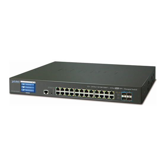
- Page 1 L3 Managed Ethernet Switch GS-5220 Switch Series Quick Installation Guide...
-
Page 2: Table Of Contents
Table of Contents 1. Package Contents ..................3 2. Requirements ..................... 5 3. Terminal Setup ................... 6 3.1 Logging on to Console ................. 7 3.2 Configuring IP Address ................. 7 3.3 Storing Current Switch Configuration ............. 9 4. Starting Web Management .................10 4.1 Logging in to the Managed Switch ............10 4.2. Saving Configuration via Web ..............13 5. Recovering Back to Default Configuration .............14 6. -
Page 3: Package Contents
1. Package Contents Thank you for purchasing PLANET GS-5220 L3 Managed Ethernet Switch series. The descriptions of this series are shown below: Gigabit Gigabit 10G Redundant Model Name RJ45 SFP+ Power Power Ports Slots Slots Budget System GS-5220-16T4S2X GS-5220-16T4S2XR GS-5220-20T4C4X 4 combo GS-5220-20T4C4XR 4 combo GS-5220-24P4X 4 combo... - Page 4 Open the box of the Managed Switch and carefully unpack it. The box should contain the following items: z The Managed Switch z Quick Installation Guide z RJ45 to RS232 Cable z Rubber Feet z Two Rack-mounting Brackets with Attachment Screws z Power Cord z SFP Dust-proof Caps Model SFP Dust-proof Caps GS-5220-16T4S2X GS-5220-16T4S2XR GS-5220-20T4C4X GS-5220-20T4C4XR GS-5220-24P4X GS-5220-24P4XR GS-5220-24PL4X GS-5220-24PL4XR...
-
Page 5: Requirements
2. Requirements z Workstations running Windows 10/XP/2003/Vista/7/8/2008, MAC OS X or later, Linux, UNIX, or other platforms are compatible with TCP/IP protocols. z Workstations are installed with Ethernet NIC (Network Interface Card) z Serial Port Connection (Terminal) The above Workstations come with COM Port (DB9) or USB-to-RS232 converter. The above Workstations have been installed with terminal emulator, such as Hyper Terminal included in Windows XP/2003. Serial cable -- one end is attached to the RS232 serial port, while the other end to the console port of the Managed Switch. -
Page 6: Terminal Setup
3. Terminal Setup To configure the system, connect a serial cable to a COM port on a PC or notebook computer and to RJ45 type of serial port of the Managed Switch. PC / Workstation with Terminal Emulation Software Managed Switch RS232 to RJ45 Cable Serial Port RJ45... -
Page 7: Logging On To Console
3.1 Logging on to Console Once the terminal is connected to the device, power on the Managed Switch and the terminal will display “running testing procedures”. Then, the following message asks to log in user name and password. The factory default user name and password are shown as follows and the login screen in Figure 3-3 appears. - Page 8 Show the current IP Address 1. At the “#” prompt, enter “show ip interface brief”. GS-5220 Series # show ip interface brief 2. The screen displays the current IP address as shown in Figure 3-4. Figure 3-4: IP Information Screen Configuring IP Address 3. At the “#” prompt, enter the following command and press <Enter> as shown in Figure 3-5. GS-5220 Series# configure terminal GS-5220 Series(config)# interface vlan 1 GS-5220 Series(config-if-vlan)# ip address 192.168.1.100 255.255.255.0 The previous command would apply the following settings for the Managed Switch.
-
Page 9: Storing Current Switch Configuration
3.3 Storing Current Switch Configuration At the “#” prompt, enter the following command and press <Enter>. # copy running-config startup-config Figure 3-6: Saving Current Configuration Command Screen If the IP is successfully configured, the Managed Switch will apply the new IP address setting immediately. You can access the Web interface of the Managed Switch through the new IP address. -
Page 10: Starting Web Management
4. Starting Web Management The following shows how to start up the Web Management of the Managed Switch. Note the Managed Switch is configured through an Ethernet connection. Please make sure the manager PC must be set to the same IP subnet address. For example, the default IP address of the Managed Switch is 192.168.0.100, then the manager PC should be set to 192.168.0.x (where x is a number between 1 and 254, except 100), and the default subnet mask is 255.255.255.0. - Page 11 Default IP Address: 192.168.0.100 Default Username: admin Default Password: admin Figure 4-2: Login Screen 3. Ater entering the password, the main screen appears as Figure 4-3 shows. Figure 4-3: Web Main Screen of Managed Switch...
- Page 12 The Switch Menu on the top and left of the Web page lets you access all the commands and statistics the Managed Switch provides. Figure 4-4: Switch Menu If you are not familiar with Switch functions or the related param- eter, press “Help icon” anytime on the Web page to get the help description.
-
Page 13: Saving Configuration Via Web
4.2. Saving Configuration via Web To save all applied changes and set the current configuration as a startup configuration, the startup-configuration file will be loaded automatically across a system reboot. 1. Click the Save icon on the top Switch Menu bar. Figure 4-5: Save Config -- Hot key 2. -
Page 14: Recovering Back To Default Configuration
5. Recovering Back to Default Configuration IP address has been changed or admin password has been forgotten – To reset the IP address to the default IP addres “192.168.0.100” or reset the login password to default value, press the hardware-based reset button on the rear panel for about 10 seconds. After the device is rebooted, you can log in to the management Web interface within the same subnet of 192.168.0.xx. -
Page 15: Customer Support
6. Customer Support Thank you for purchasing PLANET products. You can browse our online FAQ resource and User’s Manual on PLANET Web site first to check if it could solve your issue. If you need more support information, please contact PLANET switch support team. PLANET online FAQs: http://www.planet.com.tw/en/support/faq Switch support team mail address: support@planet.com.tw GS-5220 Series User’s Manual: http://www.planet.com.tw/en/support/downloads?method=category&c1=&p=&ty pe=3 (Please select your switch model name from the drop-down menu of Product Model.) Copyright © PLANET Technology Corp. 2020.
Need help?
Do you have a question about the GS-5220 Series and is the answer not in the manual?
Questions and answers