
Subscribe to Our Youtube Channel
Related Manuals for Planet GS-5220-24T4XVR


Summary of Contents for Planet GS-5220-24T4XVR
- Page 1 User’s Manual of GS-5220-24T4XV(R) Managed LCD Switch L2+ Gigabit/10 Gigabit Managed LCD Switch GS-5220-24T4XV/GS-5220-24T4XVR...
- Page 2 PLANET is a registered trademark of PLANET Technology Corp. All other trademarks belong to their respective owners. Disclaimer PLANET Technology does not warrant that the hardware will work properly in all environments and applications, and makes no warranty and representation, either implied or expressed, with respect to the quality, performance, merchantability, or fitness for a particular purpose.
-
Page 3: Table Of Contents
3.2 Management Access Overview ......................... 36 3.3 Administration Console ..........................37 3.4 Web Management ............................38 3.5 SNMP-based Network Management ......................39 3.6 PLANET Smart Discovery Utility ......................39 4. WEB CONFIGURATION ...................... 42 4.1 Main Web Page ............................44 4.2 System ................................. 46 4.2.1 Management ................................ - Page 4 User’s Manual of GS-5220-24T4XV(R) Managed LCD Switch 4.2.1.3 IP Status ..............................50 4.2.1.4 Users Configuration ........................... 51 4.2.1.5 Privilege Levels ............................54 4.2.1.6 NTP Configuration ............................. 55 4.2.1.6.1 System Time Correction Manually ......................56 4.2.1.7 Time Configuration ............................ 57 4.2.1.8 UPnP ................................. 59 4.2.1.9 DHCP Relay ..............................
- Page 5 User’s Manual of GS-5220-24T4XV(R) Managed LCD Switch 4.3.1.2 Port Statistics Overview ..........................98 4.3.1.3 Port Statistics Details..........................98 4.3.1.4 SFP Module Information .......................... 100 4.3.1.5 Port Mirror ............................... 102 4.3.2 Link Aggregation ..............................105 4.3.2.1 Static Aggregation ........................... 107 4.3.2.2 LACP Configuration ..........................109 4.3.2.3 LACP System Status ..........................
- Page 6 User’s Manual of GS-5220-24T4XV(R) Managed LCD Switch 4.3.5.7 IGMP Snooping Status ..........................171 4.3.5.8 IGMP Group Information ......................... 172 4.3.5.9 IGMPv3 Information..........................173 4.3.6 MLD Snooping ..............................174 4.3.6.1 MLD Snooping Configuration ........................174 4.3.6.2 MLD Snooping VLAN Configuration ......................175 4.3.6.3 MLD Snooping Port Group Filtering ......................
- Page 7 User’s Manual of GS-5220-24T4XV(R) Managed LCD Switch 4.4.1.5 Statistics ..............................225 4.4.2 Bandwidth Control ............................. 226 4.4.2.1 Port Policing ............................226 4.4.2.2 Port Schedule ............................227 4.4.2.3 Port Shaping ............................228 4.4.3 Storm Control ..............................230 4.4.3.1 Storm Control Configuration ........................230 4.4.4 Differentiated Service ............................
- Page 8 User’s Manual of GS-5220-24T4XV(R) Managed LCD Switch 4.5.5.2 Access Control List Configuration ......................288 4.5.5.3 ACE Configuration ........................... 290 4.5.5.4 ACL Ports Configuration .......................... 302 4.5.5.5 ACL Rate Limiters ............................ 304 4.5.6 DHCP Snooping ..............................305 4.5.6.1 DHCP Snooping Configuration ........................ 305 4.5.6.2 Snooping Table ............................
- Page 9 User’s Manual of GS-5220-24T4XV(R) Managed LCD Switch 5.2 Learning ..............................343 5.3 Forwarding & Filtering ..........................343 5.4 Store-and-Forward ........................... 343 5.5 Auto-Negotiation ............................344 6. TROUBLESHOOTING ....................... 345 APPENDIX A: Networking Connection ................346 A.1 Switch's Data RJ45 Pin Assignments - 1000Mbps, 1000BASE-T ............346 A.2 10/100Mbps, 10/100BASE-TX .........................
-
Page 10: Introduction
RJ45 to RS232 Cable Rubber Feet Two Rack-mounting Brackets with Attachment Screws Power Cord SFP Dust-proof Caps Model Name SFP Dust-proof Caps GS-5220-24T4XV GS-5220-24T4XVR If any item is found missing or damaged, please contact your local reseller for replacement. -
Page 11: Product Description
Intuitive LCD Control The GS-5220-24T4XV and GS-5220-24T4XVR come with an intuitive touch panel on its front panel to greatly promote management efficiency in large-scale networks, such as enterprises, hotels, shopping malls, government buildings, and other public areas. - Page 12 User’s Manual of GS-5220-24T4XV(R) Managed LCD Switch Redundant Ring, Fast Recovery for Critical Network Applications The GS-5220-24T4XVR supports redundant ring technology and features strong, rapid self-recovery capability to prevent interruptions and external intrusions. It incorporates advanced ITU-T G.8032 ERPS (Ethernet Ring Protection Switching) technology, IEEE 802.1s Multiple Spanning Tree Protocol (MSTP), and dual power input system into customer’s industrial...
- Page 13 Redundant AC/DC Power Supply to Ensure Continuous Operation The GS-5220-24T4XVR is particularly equipped with one 100~240V AC power supply unit and one 36~60V DC power supply unit to provide an enhanced reliable and scalable redundant power supply. The continuous power system is specifically designed to fulfill the demands of high-tech facilities requiring the highest power integrity.
- Page 14 User’s Manual of GS-5220-24T4XV(R) Managed LCD Switch Solution for IPv6 Networking With the IPv6/IPv4 dual stack and other management functions with user-friendly interfaces, the GS-5220 series is the best choice for IP surveillance, VoIP and wireless service providers to deploy the IPv6 network. More importantly, they help SMBs upgrade their network infrastructures to the IPv6 era without any monetary investment.
- Page 15 User’s Manual of GS-5220-24T4XV(R) Managed LCD Switch number or defined typical network applications. Its protection mechanism also comprises 802.1x Port-based and MAC-based user and device authentication. With the private VLAN function, communication between edge ports can be prevented to ensure user privacy. Enhanced Security and Traffic Control The GS-5220 series also provides DHCP Snooping, IP Source Guard and Dynamic ARP Inspection functions to prevent IP snooping from attack and discard ARP packets with invalid MAC address.
- Page 16 User’s Manual of GS-5220-24T4XV(R) Managed LCD Switch Applications Layer 2+ VLAN Static Routing and 10G Uplink Application With the built-in robust IPv4/IPv6 Layer 3 traffic routing protocols, the GS-5220 series ensure reliable routing between VLANs and network segments. The routing protocols can be applied by VLAN interface with up to 128 routing entries. The GS-5220 series are certainly a cost-effective and ideal solution for enterprises.
-
Page 17: How To Use This Manual
User’s Manual of GS-5220-24T4XV(R) Managed LCD Switch 1.3 How to Use This Manual This User’s Manual is structured as follows: Section 2, INSTALLATION The section explains the functions of the Managed Switch and how to physically install the Managed Switch. Section 3, SWITCH MANAGEMENT The section contains the information about the software function of the Managed Switch. -
Page 18: Product Features
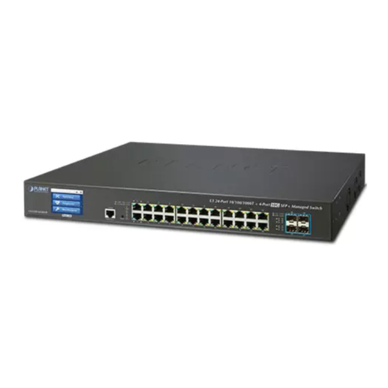
User’s Manual of GS-5220-24T4XV(R) Managed LCD Switch 1.4 Product Features Physical Port 24 10/100/1000BASE-T Gigabit RJ45 copper ports 4 10GBASE-SR/LR SFP+ slots, compatible with 1000BASE-SX/LX/BX SFP RJ45 console interface for switch basic management and setup Layer 2 Features ... - Page 19 User’s Manual of GS-5220-24T4XV(R) Managed LCD Switch 8 priority queues on all switch ports Traffic classification IEEE 802.1p CoS TOS/DSCP/IP precedence of IPv4/IPv6 packets IP TCP/UDP port number Typical network application Strict priority and Weighted Round Robin (WRR) CoS policies ...
- Page 20 SNMP trap for interface Link Up and Link Down notification System Log Reset button for system reboot or reset to factory default PLANET Smart Discovery Utility for deployment management Redundant Power System (GS-5220-24T4XVR) Redundant 100~240V AC/36-60V DC dual power ...
-
Page 21: Product Specifications
440 x 300 x 56 mm, 1.25U height Weight 3.7kg System: SYS (Green) AC/PWR (Green) DC (Green) (GS-5220-24T4XVR Only) Ring (Green) Ethernet Interfaces (Port-1 to Port-24): 1000 LNK/ACT (Green), 10/100 LNK/ACT (Orange) 1/10G SFP+ Interfaces (Port-25 to Port-28): 1G (Green), 10G (Orange) AC: Max. - Page 22 User’s Manual of GS-5220-24T4XV(R) Managed LCD Switch Auto-negotiation 10/100/1000Mbps full and half duplex mode selection Flow control disable/enable Display each port’s speed duplex mode, link status, flow control status, Port Status auto-negotiation status, trunk status TX/RX/Both Port Mirroring Many-to-1 monitor 802.1Q tagged-based VLAN Q-in-Q tunneling Private VLAN Edge (PVE)
- Page 23 User’s Manual of GS-5220-24T4XV(R) Managed LCD Switch IPv6 hardware static routing Management Basic Management Console; Telnet; Web browser; SNMP v1, v2c; 2.4-inch color LCD touch screen Interfaces Secure Management SSH, SSL, SNMP v3 Interfaces RFC 1213 MIB-II RFC 1493 Bridge MIB RFC 1643 Ethernet MIB RFC 2618 RADIUS Client MIB RFC 2665 Ether-Like MIB...
-
Page 24: Installation
User’s Manual of GS-5220-24T4XV(R) Managed LCD Switch RFC 768 UDP RFC 791 IP RFC 792 ICMP RFC 793 TFTP RFC 1112 IGMP v1 RFC 2068 HTTP RFC 2236 IGMP v2 RFC 2710 MLD v1 RFC 3376 IGMP v3 FRC 3810 MLD v2 Environment Temperature: 0 ~ 50 degrees C Operating... - Page 25 User’s Manual of GS-5220-24T4XV(R) Managed LCD Switch Figure 2-1-1: Front Panel of GS-5220-24T4XV GS-5220-24T4XVR Front Panel Figure 2-1-2: Front Panel of GS-5220-24T4XVR ■ Gigabit TP interface 10/100/1000BASE-T Copper, RJ45 twisted-pair: Up to 100 meters ■ 10 Gigabit SFP+ slot 1/10GBASE-SR/LR mini-GBIC slot, SFP+ (Small Factor Pluggable Plus) Transceiver module supports from 300 meters (multi-mode fiber) up to 10 kilometers (single mode fiber) ■...
-
Page 26: Led Indications
Figures 2-1-3 and 2-1-4 show the LED indications of the Managed Switches. GS-5220-24T4XV LED Indication Figure 2-1-3: Front Panel of GS-5220-24T4XV GS-5220-24T4XVR LED Indication Figure 2-1-4: Front Panel of GS-5220-24T4XVR System/Alert (GS-5220-24T4XV) Color Function Green Lights to indicate that the Switch has power. -
Page 27: Switch Rear Panel
GS-5220-24T4XV Rear Panel Figure 2-1-5: Rear Panel of GS-5220-24T4XV GS-5220-24T4XVR Rear Panel Figure 2-1-6: Rear Panel of GS-5220-24T4XVR ■ AC Power Receptacle For compatibility with electrical voltages in most areas of the world, the Managed Switch’s power supply can automatically... - Page 28 User’s Manual of GS-5220-24T4XV(R) Managed LCD Switch Plug the female end of the power cord firmly into the receptacle on the rear panel of the Managed Switch and the other end of the power cord into an electrical outlet and the power will be ready. The device is a power-required device, which means it will not work till it is powered.
-
Page 29: Installing The Switch
In the installation steps below, this manual uses the GS-5220-48T4X as an example. However, the steps for PLANET GS-5220 series are similar. 2.2.1 Desktop Installation To install the Managed Switch on desktop or shelf, please follow these steps: Step 1: Attach the rubber feet to the recessed areas on the bottom of the Managed Switch. -
Page 30: Rack Mounting
User’s Manual of GS-5220-24T4XV(R) Managed LCD Switch Connect one end of the power cable to the Managed Switch. Connect the power plug of the power cable to a standard wall outlet. When the Managed Switch receives power, the Power LED should remain solid Green. 2.2.2 Rack Mounting To install the Managed Switch in a 19-inch standard rack, please follow the instructions described below. -
Page 31: Installing The Sfp/Sfp+ Transceiver
Figure 2-2-4 shows.. Figure 2-2-4: Plug-in the SFP/SFP+ Transceiver Approved PLANET SFP/SFP+ Transceivers PLANET Managed Switch supports both single mode and multi-mode SFP/SFP+ transceivers. The following list of approved PLANET SFP/SFP+ transceivers is correct at the time of publication:... - Page 32 User’s Manual of GS-5220-24T4XV(R) Managed LCD Switch Gigabit Ethernet Transceiver (1000BASE-X SFP) Model Speed (Mbps) Connector Interface Fiber Mode Distance Wavelength (nm) Operating Temp. MGB-GT 1000 Copper 100m 0 ~ 60 degrees C MGB-SX 1000 Multi Mode 550m 850nm 0 ~ 60 degrees C MGB-SX2 1000 Multi Mode...
- Page 33 1270nm 0 ~ 60 degrees C It is recommended to use PLANET SFP/SFP+ on the Managed Switch. If you insert an SFP/SFP+ transceiver that is not supported, the Managed Switch will not recognize it. Before we connect the GS-5220 series to the other network device, we have to make sure both sides of the SFP transceivers are with the same media type, for example: 1000BASE-SX to 1000BASE-SX, 1000BASE-LX to 1000BASE-LX.
- Page 34 User’s Manual of GS-5220-24T4XV(R) Managed LCD Switch Figure 2-2-5: How to Pull Out the SFP/SFP+ Transceiver Never pull out the module without lifting up the lever of the module and turning it to a horizontal position. Directly pulling out the module could damage the module and the SFP/SFP+ module slot of the Managed Switch.
-
Page 35: Switch Management
User’s Manual of GS-5220-24T4XV(R) Managed LCD Switch 3. SWITCH MANAGEMENT This chapter explains the methods that you can use to configure management access to the Managed Switch. It describes the types of management applications and the communication and management protocols that deliver data between your management device (workstation or personal computer) and the system. -
Page 36: Management Access Overview
User’s Manual of GS-5220-24T4XV(R) Managed LCD Switch 3.2 Management Access Overview The Managed Switch gives you the flexibility to access and manage it using any or all of the following methods: An administration console Web browser interface An external SNMP-based network management application The administration console and Web browser interface support are embedded in the Managed Switch software and are available for immediate use. -
Page 37: Administration Console
User’s Manual of GS-5220-24T4XV(R) Managed LCD Switch 3.3 Administration Console The administration console is an internal, character-oriented, and command line user interface for performing system administration such as displaying statistics or changing option settings. Using this method, you can view the administration console from a terminal, personal computer, Apple Macintosh, or workstation connected to the Managed Switch's console (serial) port. -
Page 38: Web Management
User’s Manual of GS-5220-24T4XV(R) Managed LCD Switch You can change these settings, if desired, after you log on. This management method is often preferred because you can remain connected and monitor the system during system reboots. Also, certain error messages are sent to the serial port, regardless of the interface through which the associated action was initiated. -
Page 39: Snmp-Based Network Management
3.6 PLANET Smart Discovery Utility For easily listing the Managed Switch in your Ethernet environment, the Planet Smart Discovery Utility from user’s manual CD-ROM is an ideal solution. The following installation instructions are to guide you to running the Planet Smart Discovery Utility. - Page 40 User’s Manual of GS-5220-24T4XV(R) Managed LCD Switch Figure 3-1-6: Planet Smart Discovery Utility Screen If there are two LAN cards or above in the same administrator PC, choose a different LAN card by using the “Select Adapter” tool. Press the “Refresh” button for the currently connected devices in the discovery list as the screen shows below:...
- Page 41 To click the “Control Packet Force Broadcast” function, it allows you to assign a new setting value to the Web Smart Switch under a different IP subnet address. Press the “Connect to Device” button and the Web login screen appears in Figure 3-1-4. Press the “Exit” button to shut down the Planet Smart Discovery Utility.
-
Page 42: Web Configuration
User’s Manual of GS-5220-24T4XV(R) Managed LCD Switch 4. WEB CONFIGURATION This section introduces the configuration and functions of the Web-based management from Managed Switch. About Web-based Management The Managed Switch offers management features that allow users to manage the Managed Switch from anywhere on the network through a standard browser such as Microsoft Internet Explorer. - Page 43 User’s Manual of GS-5220-24T4XV(R) Managed LCD Switch When the following login screen appears, please enter the default username "admin" with password “admin” (or the username/password you have changed via console) to log in the main screen of Managed Switch. The login screen in Figure 4-1-2 appears.
-
Page 44: Main Web Page
User’s Manual of GS-5220-24T4XV(R) Managed LCD Switch Figure 4-1-3: Web Main Page Now, you can use the Web management interface to continue the switch management or manage the Managed Switch by Web interface. The Switch Menu on the left of the web page lets you access all the commands and statistics the Managed Switch provides. - Page 45 User’s Manual of GS-5220-24T4XV(R) Managed LCD Switch State Link Down RJ45 Ports SFP Ports Main Menu Using the onboard web agent, you can define system parameters, manage and control the Managed Switch, and all its ports, or monitor network conditions. Via the Web-Management, the administrator can set up the Managed Switch by selecting the functions those listed in the Main Function.
-
Page 46: System
User’s Manual of GS-5220-24T4XV(R) Managed LCD Switch 4.2 System Use the System menu items to display and configure basic administrative details of the Managed Switch. Under the System, the following topics are provided to configure and view the system information. This section has the following items: ■... -
Page 47: Management
User’s Manual of GS-5220-24T4XV(R) Managed LCD Switch 4.2.1 Management 4.2.1.1 System Information The System Information page provides information for the current device information. System Information page helps a switch administrator to identify the hardware MAC address, software version and system uptime. The screen in Figure 4-2-1 appears. -
Page 48: Ip Configuration
User’s Manual of GS-5220-24T4XV(R) Managed LCD Switch Auto-refresh : Check this box to refresh the page automatically. Automatic refresh occurs every 3 seconds. : Click to refresh the page; any changes made locally will be undone. 4.2.1.2 IP Configuration The IP Configuration includes the IP Configuration, IP Interface and IP Routes. The configured column is used to view or change the IP configuration. - Page 49 User’s Manual of GS-5220-24T4XV(R) Managed LCD Switch DHCPv6-enabled interface will be used. From this DHCPv6 interface Specify from which DHCPv6-enabled interface a provided domain name should be preferred. When DNS proxy is enabled, system will relay DNS requests to the DNS Proxy currently configured DNS server, and reply as a DNS resolver to the client devices on the network.
-
Page 50: Ip Status
User’s Manual of GS-5220-24T4XV(R) Managed LCD Switch length). The IP address of the IP gateway. Valid format is dotted decimal Gateway notation or a valid IPv6 notation. Gateway and Network must be of the same type. The VLAN ID (VID) of the specific IPv6 interface associated with the Next Hop VLAN gateway. -
Page 51: Users Configuration
User’s Manual of GS-5220-24T4XV(R) Managed LCD Switch Figure 4-2-1-3: IP Status Page Screenshot The page includes the following fields: Object Description IP Interfaces Interface The name of the interface. The address type of the entry. This may be LINK or IPv4. Type Address The current address of the interface (of the given type). - Page 52 User’s Manual of GS-5220-24T4XV(R) Managed LCD Switch than the group privilege level to have the access to that group. By default setting, most groups privilege level 5 has the read-only access and privilege level 10 has the read-write access. And the system maintenance (software upload, factory defaults and etc.) needs user privilege level 15.
- Page 53 User’s Manual of GS-5220-24T4XV(R) Managed LCD Switch refer to each group privilege level. User's privilege should be same or greater than the group privilege level to have the access of that group. By default setting, most groups privilege level 5 has the read-only access and privilege level 10 has the read-write access.
-
Page 54: Privilege Levels
User’s Manual of GS-5220-24T4XV(R) Managed LCD Switch 4.2.1.5 Privilege Levels This page provides an overview of the privilege levels. After setup is completed, please press the “Apply” button to take effect. Please login web interface with new user name and password and the screen in Figure 4-2-1-7 appears. -
Page 55: Ntp Configuration
User’s Manual of GS-5220-24T4XV(R) Managed LCD Switch System: Contact, Name, Location, Timezone, Log. Security: Authentication, System Access Management, Port (contains Dot1x port, MAC based and the MAC Address Limit), ACL, HTTPS, SSH, ARP Inspection and IP source guard. ... -
Page 56: System Time Correction Manually
User’s Manual of GS-5220-24T4XV(R) Managed LCD Switch Figure 4-2-1-8: NTP Configuration Page Screenshot The page includes the following fields: Object Description Mode Indicates the NTP mode operation. Possible modes are: Enabled: Enable NTP mode operation. When enabling NTP mode operation, the agent forward and transfer NTP messages between the clients and the server when they are not on the same subnet domain. -
Page 57: Time Configuration
User’s Manual of GS-5220-24T4XV(R) Managed LCD Switch The page includes the following fields: Object Description User Manually Indicates the NTP mode as manual operation. Possible modes are: Enabled: Enable NTP manual mode operation. When enabling NTP user manually mode operation, the system time will follow the date setting. ... - Page 58 User’s Manual of GS-5220-24T4XV(R) Managed LCD Switch Figure 4-2-1-9: Time Configuration Page Screenshot The page includes the following fields: Object Description Time Zone Lists various Time Zones worldwide. Select appropriate Time Zone from the drop-down and click Save to set. ...
-
Page 59: Upnp
User’s Manual of GS-5220-24T4XV(R) Managed LCD Switch Day - Select the starting day. Month - Select the starting month. Hours - Select the starting hour. Minutes - Select the starting minute. End Time Settings Week - Select the ending week number. ... - Page 60 User’s Manual of GS-5220-24T4XV(R) Managed LCD Switch Object Description Mode Indicates the UPnP operation mode. Possible modes are: Enabled: Enable UPnP mode operation. Disabled: Disable UPnP mode operation. When the mode is enabled, two ACEs are added automatically to trap UPnP related packets to CPU.
-
Page 61: Dhcp Relay
User’s Manual of GS-5220-24T4XV(R) Managed LCD Switch 4.2.1.9 DHCP Relay Configure DHCP Relay on this page. DHCP Relay is used to forward and transfer DHCP messages between the clients and the server when they are not on the same subnet domain. The DHCP option 82 enables a DHCP relay agent to insert specific information into a DHCP request packets when forwarding client DHCP packets to a DHCP server and remove the specific information from a DHCP reply packets when forwarding server DHCP packets to a DHCP client. -
Page 62: Dhcp Relay Statistics
User’s Manual of GS-5220-24T4XV(R) Managed LCD Switch Relay Information Indicates the DHCP relay information mode option operation. Possible modes Mode are: Enabled: Enable DHCP relay information mode operation. When enabling DHCP relay information mode operation, the agent inserts specific information (option82) into a DHCP message when forwarding to DHCP server and removing it from a DHCP message when transferring to DHCP client. - Page 63 User’s Manual of GS-5220-24T4XV(R) Managed LCD Switch The page includes the following fields: Server Statistics Object Description Transmit to Server The packet number that relayed from client to server. Transmit Error The packet number that erroneously sent packets to clients. ...
- Page 64 User’s Manual of GS-5220-24T4XV(R) Managed LCD Switch : Clears all statistics.
-
Page 65: Cpu Load
User’s Manual of GS-5220-24T4XV(R) Managed LCD Switch 4.2.1.11 CPU Load This page displays the CPU load, using an SVG graph. The load is measured as average over the last 100ms, 1 sec and 10 seconds intervals. The last 120 samples are graphed, and the last numbers are displayed as text as well. In order to display the SVG graph, your browser must support the SVG format. -
Page 66: System Log
User’s Manual of GS-5220-24T4XV(R) Managed LCD Switch 4.2.1.12 System Log The Managed Switch system log information is provided here. The System Log screen in Figure 4-2-1-15 appears. Figure 4-2-1-15: System Log Page Screenshot The page includes the following fields: Object Description ... -
Page 67: Detailed Log
User’s Manual of GS-5220-24T4XV(R) Managed LCD Switch : Updates the system log entries, starting from the first available entry ID. : Updates the system log entries, ending at the last entry currently displayed. : Updates the system log entries, starting from the last entry currently displayed. : Updates the system log entries, ending at the last available entry ID. -
Page 68: Remote Syslog
User’s Manual of GS-5220-24T4XV(R) Managed LCD Switch 4.2.1.14 Remote Syslog Configure remote syslog on this page. The Remote Syslog screen in Figure 4-2-1-17 appears. Figure 4-2-1-17: Remote Syslog Page Screenshot The page includes the following fields: Object Description Mode Indicates the server mode operation. -
Page 69: Smtp Configuration
User’s Manual of GS-5220-24T4XV(R) Managed LCD Switch 4.2.1.15 SMTP Configuration This page facilitates an SMTP Configuration on the switch. The SMTP Configure screen in Figure 4-2-1-18 appears. Figure 4-2-1-18: SMTP Configuration Page Screenshot The page includes the following fields: Object Description ... -
Page 70: Simple Network Management Protocol
User’s Manual of GS-5220-24T4XV(R) Managed LCD Switch : Click to undo any changes made locally and revert to previously saved values. 4.2.2 Simple Network Management Protocol 4.2.2.1 SNMP Overview The Simple Network Management Protocol (SNMP) is an application layer protocol that facilitates the exchange of management information between network devices. -
Page 71: Snmp System Configuration
User’s Manual of GS-5220-24T4XV(R) Managed LCD Switch SNMP Community An SNMP community is the group that devices and management stations running SNMP belong to. It helps define where information is sent. The community name is used to identify the group. An SNMP device or agent may belong to more than one SNMP community. - Page 72 User’s Manual of GS-5220-24T4XV(R) Managed LCD Switch Indicates the SNMP supported version. Possible versions are: Version SNMP v1: Set SNMP supported version 1. SNMP v2c: Set SNMP supported version 2c. SNMP v3: Set SNMP supported version 3. ...
-
Page 73: Snmp Trap Configuration
User’s Manual of GS-5220-24T4XV(R) Managed LCD Switch 4.2.2.3 SNMP Trap Configuration Configure SNMP trap on this page. The SNMP Trap Configuration screen in Figure 4-2-2-3 appears. Figure 4-2-2-3: SNMP Trap Configuration Page Screenshot The page includes the following fields: Object Description ... - Page 74 User’s Manual of GS-5220-24T4XV(R) Managed LCD Switch Indicates the SNMP trap supported version. Possible versions are: Trap Version SNMP v1: Set SNMP trap supported version 1. SNMP v2c: Set SNMP trap supported version 2c. SNMP v3: Set SNMP trap supported version 3. ...
-
Page 75: Snmp System Information
User’s Manual of GS-5220-24T4XV(R) Managed LCD Switch AAA Indicates that the AAA group's traps. Possible traps are: Authentication Fail : Enable/disable SNMP trap authentication failure trap. Switch Indicates that the Switch group's traps. Possible traps are: STP: Enable/disable STP trap. ... -
Page 76: Snmpv3 Communities
User’s Manual of GS-5220-24T4XV(R) Managed LCD Switch to 126. 4.2.2.5 SNMPv3 Communities Configure SNMPv3 communities table on this page. The entry index key is Community. The SNMPv3 Communities screen in Figure 4-2-2-5 appears. Figure 4-2-2-5: SNMPv3 Communities Configuration Page Screenshot The page includes the following fields: Object Description... -
Page 77: Snmpv3 Users
User’s Manual of GS-5220-24T4XV(R) Managed LCD Switch 4.2.2.6 SNMPv3 Users Configure SNMPv3 users table on this page. The entry index keys are Engine ID and User Name. The SNMPv3 Users screen in Figure 4-2-2-6 appears. Figure 4-2-2-6: SNMPv3 Users Configuration Page Screenshot The page includes the following fields: Object Description... -
Page 78: Snmpv3 Groups
User’s Manual of GS-5220-24T4XV(R) Managed LCD Switch MD5: An optional flag to indicate that this user using MD5 authentication protocol. SHA: An optional flag to indicate that this user using SHA authentication protocol. The value of security level cannot be modified if entry already exist. That means must first ensure that the value is set correctly. -
Page 79: Snmpv3 Views
User’s Manual of GS-5220-24T4XV(R) Managed LCD Switch Figure 4-2-2-7: SNMPv3 Groups Configuration Page Screenshot The page includes the following fields: Object Description Delete Check to delete the entry. It will be deleted during the next save. Security Model Indicates the security model that this entry should belong to. -
Page 80: Snmpv3 Access
User’s Manual of GS-5220-24T4XV(R) Managed LCD Switch Object Description Delete Check to delete the entry. It will be deleted during the next save. View Name A string identifying the view name that this entry should belong to. The allowed string length is 1 to 32, and the allowed content is the ASCII characters from 33 to 126. -
Page 81: Rmon
User’s Manual of GS-5220-24T4XV(R) Managed LCD Switch Object Description Delete Check to delete the entry. It will be deleted during the next save. Group Name A string identifying the group name that this entry should belong to. The allowed string length is 1 to 32, and the allowed content is the ASCII characters from 33 to 126. -
Page 82: Rmon Alarm Configuration
User’s Manual of GS-5220-24T4XV(R) Managed LCD Switch Statistics: Maintain basic usage and error statistics for each subnet monitored by the agent. History: Record periodical statistic samples available from statistics. Alarm: Allow management console users to set any count or integer for sample intervals and alert thresholds for RMON agent records. -
Page 83: Rmon Alarm Status
User’s Manual of GS-5220-24T4XV(R) Managed LCD Switch InUnknownProtos: the number of the inbound packets that is discarded because of the unknown or un-support protocol. OutOctets: The number of octets transmitted out of the interface, including framing characters. OutUcastPkts: The number of uni-cast packets that requests to transmit. -
Page 84: Rmon Event Configuration
User’s Manual of GS-5220-24T4XV(R) Managed LCD Switch 4-2-3-2 appears. Figure 4-2-3-2: RMON Alarm Overview Page Screenshot The page includes the following fields: Object Description ID Indicates the index of Alarm control entry. Interval Indicates the interval in seconds for sampling and comparing the rising and falling threshold. - Page 85 User’s Manual of GS-5220-24T4XV(R) Managed LCD Switch Figure 4-2-3-3 RMON Event Configuration Page Screenshot The page includes the following fields: Object Description Delete Check to delete the entry. It will be deleted during the next save. ID Indicates the index of the entry. The range is from 1 to 65535. ...
-
Page 86: Rmon Event Status
User’s Manual of GS-5220-24T4XV(R) Managed LCD Switch 4.2.3.4 RMON Event Status This page provides an overview of RMON Event table entries. Each page shows up to 99 entries from the Event table, default being 20, selected through the "entries per page" input field. When first visited, the web page will show the first 20 entries from the beginning of the Event table. -
Page 87: Rmon History Configuration
User’s Manual of GS-5220-24T4XV(R) Managed LCD Switch 4.2.3.5 RMON History Configuration Configure RMON History table on this page. The entry index key is ID; screen in Figure 4-2-3-5 appears. Figure 4-2-3-5: RMON History Configuration Page Screenshot The page includes the following fields: Object Description ... -
Page 88: Rmon History Status
User’s Manual of GS-5220-24T4XV(R) Managed LCD Switch 4.2.3.6 RMON History Status This page provides an detail of RMON history entries; screen in Figure 4-2-3-6 appears. Figure 4-2-3-6: RMON History Overview Page Screenshot The page includes the following fields: Object Description ... -
Page 89: Rmon Statistics Configuration
User’s Manual of GS-5220-24T4XV(R) Managed LCD Switch Coll. The best estimate of the total number of collisions in this Ethernet segment. Utilization The best estimate of the mean physical layer network utilization on this interface during this sampling interval, in hundredths of a percent. Buttons : Click to refresh the page immediately. -
Page 90: Rmon Statistics Status
User’s Manual of GS-5220-24T4XV(R) Managed LCD Switch 4.2.3.8 RMON Statistics Status This page provides an overview of RMON Statistics entries. Each page shows up to 99 entries from the Statistics table, default being 20, selected through the "entries per page" input field. When first visited, the web page will show the first 20 entries from the beginning of the Statistics table. -
Page 91: Dhcp Server
User’s Manual of GS-5220-24T4XV(R) Managed LCD Switch CRC. Coll. The best estimate of the total number of collisions in this Ethernet segment. 64 Bytes The total number of packets (including bad packets) received that were 64 octets in length. ... - Page 92 User’s Manual of GS-5220-24T4XV(R) Managed LCD Switch Figure 4-2-4-1: DHCP server mode Page Screenshot The page includes the following fields: Object Description Mode Configure the operation mode per system. Possible modes are: Enabled: Enable DHCP server per system. Disabled: Disable DHCP server pre system. ...
-
Page 93: Lcd
User’s Manual of GS-5220-24T4XV(R) Managed LCD Switch Buttons : Click to add a new VLAN range. : Click to apply changes Click to undo any changes made locally and revert to previously saved values. 4.2.5 LCD 4.2.5.1 LCD Management This page offers many options for you to manage LCD control panel. Figure 4-2-5-1: LCD Management Page Screenshot The page includes the following fields: Object... - Page 94 User’s Manual of GS-5220-24T4XV(R) Managed LCD Switch Time Read Only Mode Enable: allows user enable "read only" mode feature to prevent someone from changing the device’s settings by LCD panel. Disable: allows user to disable "read only" mode feature. ...
-
Page 95: Switching
User’s Manual of GS-5220-24T4XV(R) Managed LCD Switch 4.3 Switching 4.3.1 Port Management Use the Port Menu to display or configure the Managed Switch's ports. This section has the following items: Port Configuration Configures port connection settings Port Statistics Overview Lists Ethernet and RMON port statistics ... - Page 96 User’s Manual of GS-5220-24T4XV(R) Managed LCD Switch Select any available link speed for the given switch port. Draw the menu bar to Configured Link Speed select the mode. Copper interface: Auto – It is default mode. Set up Auto negotiation. ...
- Page 97 User’s Manual of GS-5220-24T4XV(R) Managed LCD Switch...
-
Page 98: Port Statistics Overview
User’s Manual of GS-5220-24T4XV(R) Managed LCD Switch 4.3.1.2 Port Statistics Overview This page provides an overview of general traffic statistics for all switch ports. The Port Statistics Overview screen in Figure 4-3-1-2 appears. Figure 4-3-1-2: Port Statistics Overview Page Screenshot The displayed counters are: Object Description... - Page 99 User’s Manual of GS-5220-24T4XV(R) Managed LCD Switch to display. The displayed counters are the totals for receive and transmit, the size counters for receive and transmit, and the error counters for receive and transmit. The Detailed Port Statistics screen in Figure 4-3-1-3 appears.
-
Page 100: Sfp Module Information
User’s Manual of GS-5220-24T4XV(R) Managed LCD Switch sizes. Receive and Transmit Queue Counters The number of received and transmitted packets per input and output queue. Receive Error Counters Object Description Rx Drops The number of frames dropped due to lack of receive buffers or egress congestion. - Page 101 User’s Manual of GS-5220-24T4XV(R) Managed LCD Switch the hyperlink of port no. to check the statistics on a specific interface. The SFP Module Information screen in Figure 4-3-1-4 appears. Figure 4-3-1-4: SFP Module Information for Switch Page Screenshot The page includes the following fields: Object Description ...
-
Page 102: Port Mirror
User’s Manual of GS-5220-24T4XV(R) Managed LCD Switch SFP Monitor Event Alert: send trap Warning Temperature: degrees C Check SFP Monitor Event Alert box; it will be in accordance with your warning temperature setting and allows users to record message out via SNMP Trap. Auto-refresh : Check this box to enable an automatic refresh of the page at regular intervals. - Page 103 User’s Manual of GS-5220-24T4XV(R) Managed LCD Switch Mirror Port Configuration The Port Mirror screen in Figure 4-3-1-6 appears.and click the session ID to Figure 4-3-1-7 Figure 4-3-1-6: Mirror Configuration Page Screenshot Figure 4-3-1-7: Mirror Configuration Page Screenshot The page includes the following fields: Object Description ...
- Page 104 User’s Manual of GS-5220-24T4XV(R) Managed LCD Switch Source The switch is a source node for monitor flow. source port(s), reflector port are located on this switch. RMirror destination The switch is an end node for monitor flow. destination port(s) is located on this switch. ...
-
Page 105: Link Aggregation
User’s Manual of GS-5220-24T4XV(R) Managed LCD Switch : Click to undo any changes made locally and revert to previously saved values. 4.3.2 Link Aggregation Port Aggregation optimizes port usage by linking a group of ports together to form a single Link Aggregated Groups (LAGs). Port Aggregation multiplies the bandwidth between the devices, increases port flexibility, and provides link redundancy. - Page 106 User’s Manual of GS-5220-24T4XV(R) Managed LCD Switch Figure 4-3-2-1: Link Aggregation The Link Aggregation Control Protocol (LACP) provides a standardized means for exchanging information between Partner Systems that require high speed redundant links. Link aggregation lets you group up to eight consecutive ports into a single dedicated connection.
-
Page 107: Static Aggregation
User’s Manual of GS-5220-24T4XV(R) Managed LCD Switch Disconnect all link aggregation port cables or disable the link aggregation ports before removing a port link aggregation to avoid creating a data loop. It allows a maximum of 10 ports to be aggregated at the same time. The Managed Switch support Gigabit Ethernet ports (up to 5 groups). - Page 108 User’s Manual of GS-5220-24T4XV(R) Managed LCD Switch Object Description Source MAC Address The Source MAC address can be used to calculate the destination port for the frame. Check to enable the use of the Source MAC address, or uncheck to disable.
-
Page 109: Lacp Configuration
User’s Manual of GS-5220-24T4XV(R) Managed LCD Switch .Object Description Group ID Indicates the group ID for the settings contained in the same row. Group ID "Normal" indicates there is no aggregation. Only one group ID is valid per port. ... -
Page 110: Lacp System Status
User’s Manual of GS-5220-24T4XV(R) Managed LCD Switch Object Description Port The switch port number. LACP Enabled Controls whether LACP is enabled on this switch port. LACP will form an aggregation when 2 or more ports are connected to the same partner. ... -
Page 111: Lacp Port Status
User’s Manual of GS-5220-24T4XV(R) Managed LCD Switch The page includes the following fields: Object Description Aggr ID The Aggregation ID associated with this aggregation instance. For LLAG the id is shown as 'isid:aggr-id' and for GLAGs as 'aggr-id' Partner System ID The system ID (MAC address) of the aggregation partner. -
Page 112: Vlan
User’s Manual of GS-5220-24T4XV(R) Managed LCD Switch join the aggregation group but will join if other port leaves. Meanwhile it's LACP status is disabled. The key assigned to this port. Only ports with the same key can aggregate together. ... -
Page 113: Ieee 802.1Q Vlan
User’s Manual of GS-5220-24T4XV(R) Managed LCD Switch The Managed Switch's default is to assign all ports to a single 802.1Q VLAN named DEFAULT_VLAN. As new VLAN is created, the member ports assigned to the new VLAN will be removed from the DEFAULT_ VLAN port member list. The DEFAULT_VLAN has a VID = 1. This section has the following items: ... - Page 114 User’s Manual of GS-5220-24T4XV(R) Managed LCD Switch ■ IEEE 802.1Q Standard IEEE 802.1Q (tagged) VLAN are implemented on the Switch. 802.1Q VLAN require tagging, which enables them to span the entire network (assuming all switches on the network are IEEE 802.1Q-compliant). VLAN allow a network to be segmented in order to reduce the size of broadcast domains.
- Page 115 User’s Manual of GS-5220-24T4XV(R) Managed LCD Switch The Ether Type and VLAN ID are inserted after the MAC source address, but before the original Ether Type/Length or Logical Link Control. Because the packet is now a bit longer than it was originally, the Cyclic Redundancy Check (CRC) must be recalculated.
-
Page 116: Vlan Port Configuration
User’s Manual of GS-5220-24T4XV(R) Managed LCD Switch Before enabling VLANs for the switch, you must first assign each port to the VLAN group(s) in which it will participate. By default all ports are assigned to VLAN 1 as untagged ports. Add a port as a tagged port if you want it to carry traffic for one or more VLANs, and any intermediate network devices or the host at the other end of the connection supports VLANs. - Page 117 User’s Manual of GS-5220-24T4XV(R) Managed LCD Switch Tagged: Ports with tagging enabled will put the VID number, priority and other VLAN information into the header of all packets that flow into those ports. If a packet has previously been tagged, the port will not alter the packet, thus keeping the VLAN information intact.
- Page 118 User’s Manual of GS-5220-24T4XV(R) Managed LCD Switch The Managed Switch supports multiple VLAN tags and can therefore be used in MAN applications as a provider bridge, aggregating traffic from numerous independent customer LANs into the MAN (Metro Access Network) space. One of the purposes of the provider bridge is to recognize and use VLAN tags so that the VLANs in the MAN space can be used independent of the customers’...
- Page 119 User’s Manual of GS-5220-24T4XV(R) Managed LCD Switch Object Description Allowed Access This field shows the allowed Access VLANs, it only affects ports configured as VLANs Access ports. Ports in other modes are members of all VLANs specified in the Allowed VLANs field.
- Page 120 User’s Manual of GS-5220-24T4XV(R) Managed LCD Switch default is 1 Accepts untagged and C-tagged frames Discards all frames that are not classified to the Access VLAN On egress all frames classified to the Access VLAN are transmitted untagged.
- Page 121 User’s Manual of GS-5220-24T4XV(R) Managed LCD Switch On ingress, all frames, whether carrying a VLAN tag or not, get classified to the Port VLAN, and possible tags are not removed on egress. ■ C-Port: On ingress, frames with a VLAN tag with TPID = 0x8100 get classified to the VLAN ID embedded in the tag.
-
Page 122: Vlan Membership Status
User’s Manual of GS-5220-24T4XV(R) Managed LCD Switch frames are transmitted with the relevant tag. ■ Tag All All frames, whether classified to the Port VLAN or not, are transmitted with a tag. ■ Untag All All frames, whether classified to the Port VLAN or not, are transmitted without a tag. - Page 123 User’s Manual of GS-5220-24T4XV(R) Managed LCD Switch Figure 4-3-3-4: VLAN Membership Status for Static User Page Screenshot The page includes the following fields: Object Description A VLAN User is a module that uses services of the VLAN management VLAN User functionality to configure VLAN memberships and VLAN port configuration such as PVID, UVID.
-
Page 124: Vlan Port Status
User’s Manual of GS-5220-24T4XV(R) Managed LCD Switch Buttons : Select VLAN Users from this drop down list. Auto-refresh : Check this box to refresh the page automatically. Automatic refresh occurs every 3 seconds. : Click to refresh the page immediately. : Updates the table starting from the first entry in the VLAN Table, i.e. - Page 125 User’s Manual of GS-5220-24T4XV(R) Managed LCD Switch the classified VLAN of the frame, the frame is discarded. Frame Type Shows whether the port accepts all frames or only tagged frames. This parameter affects VLAN ingress processing. If the port only accepts tagged frames, untagged frames received on that port are discarded.
-
Page 126: Port Isolation
User’s Manual of GS-5220-24T4XV(R) Managed LCD Switch 4.3.3.6 Port Isolation Overview When a VLAN is configured to be a private VLAN, communication between ports within that VLAN can be prevented. Two application examples are provided in this section: Customers connected to an ISP can be members of the same VLAN, but they are not allowed to communicate with each other within that VLAN. - Page 127 User’s Manual of GS-5220-24T4XV(R) Managed LCD Switch The configuration of promiscuous and isolated ports applies to all private VLANs. When traffic comes in on a promiscuous port in a private VLAN, the VLAN mask from the VLAN table is applied. When traffic comes in on an isolated port, the private VLAN mask is applied in addition to the VLAN mask from the VLAN table.
-
Page 128: Vlan Setting Example
User’s Manual of GS-5220-24T4XV(R) Managed LCD Switch 4.3.3.7 VLAN setting example: Separate VLAN 802.1Q VLAN Trunk Port Isolate 4.3.3.7.1 Two Separate 802.1Q VLANs The diagram shows how the Managed Switch handle Tagged and Untagged traffic flow for two VLANs. VLAN Group 2 and VLAN Group 3 are separated VLAN. - Page 129 User’s Manual of GS-5220-24T4XV(R) Managed LCD Switch While [PC-1] transmit an untagged packet enters Port-1, the Managed Switch will tag it with a VLAN Tag=2. [PC-2] and [PC-3] will received the packet through Port-2 and Port-3. [PC-4],[PC-5] and [PC-6] received no packet. While the packet leaves Port-2, it will be stripped away it tag becoming an untagged packet.
-
Page 130: Vlan Trunking Between Two 802.1Q Aware Switches
User’s Manual of GS-5220-24T4XV(R) Managed LCD Switch Figure 4-3-3-9: Change Port VLAN of Port 1~3 to be VLAN2 and Port VLAN of Port 4~6 to be VLAN3 Enable VLAN Tag for specific ports Link Type: Port-3 (VLAN-2) and Port-6 (VLAN-3) Change Port 3 Mode as Trunk, Selects Egress Tagging as Tag All and Types 2 in the Allowed VLANs column. - Page 131 User’s Manual of GS-5220-24T4XV(R) Managed LCD Switch Figure 4-3-3-11: VLAN Trunking Diagram Setup steps Add VLAN Group Add two VLANs – VLAN 2 and VLAN 3 Type 1-3 in Allowed Access VLANs column, the 1-3 is including VLAN1 and 2 and 3. Figure 4-3-3-12: Add VLAN 2 and VLAN 3 Assign VLAN Member and PVID for each port : VLAN 2 : Port-1,Port-2 and Port-3...
- Page 132 User’s Manual of GS-5220-24T4XV(R) Managed LCD Switch Figure 4-3-3-13: Changes Port VLAN of Port 1~3 to be VLAN2 and Port VLAN of Port 4~6 to be VLAN3 For the VLAN ports connecting to the hosts, please refer to 4.6.10.1 examples. The following steps will focus on the VLAN Trunk port configuration.
-
Page 133: Port Isolate
User’s Manual of GS-5220-24T4XV(R) Managed LCD Switch Repeat Steps 1 to 6, set up the VLAN Trunk port at the partner switch and add more VLANs to join the VLAN trunk, repeat Steps 1 to 3 to assign the Trunk port to the VLANs. 4.3.3.7.3 Port Isolate The diagram shows how the Managed Switch handles isolated and promiscuous ports, and the each PC is not able to access the isolated port of each other’s PCs. -
Page 134: Mac-Based Vlan
User’s Manual of GS-5220-24T4XV(R) Managed LCD Switch 4.3.3.8 MAC-based VLAN The MAC-based VLAN entries can be configured here. This page allows for adding and deleting MAC-based VLAN entries and assigning the entries to different ports. This page shows only static entries. The MAC-based VLAN screen in Figure 4-3-3-18 appears. -
Page 135: Protocol-Based Vlan
User’s Manual of GS-5220-24T4XV(R) Managed LCD Switch : Click to add a new MAC-based VLAN entry. : Click to apply changes : Click to undo any changes made locally and revert to previously saved values. Auto-refresh : Check this box to refresh the page automatically. Automatic refresh occurs every 3 seconds. : Click to refresh the page immediately. - Page 136 User’s Manual of GS-5220-24T4XV(R) Managed LCD Switch Value Valid value that can be entered in this text field depends on the option selected from the preceding Frame Type selection menu. Below is the criteria for three different Frame Types: For Ethernet: Values in the text field when Ethernet is selected as a Frame Type is called etype.
-
Page 137: Protocol-Based Vlan Membership
User’s Manual of GS-5220-24T4XV(R) Managed LCD Switch Auto-refresh : Check this box to refresh the page automatically. Automatic refresh occurs every 3 seconds. : Click to refresh the page immediately. 4.3.3.10 Protocol-based VLAN Membership This page allows you to map a already configured Group Name to a VLAN for the switch. The Group Name to VLAN Mapping Table screen in Figure 4-3-3-20 appears. - Page 138 User’s Manual of GS-5220-24T4XV(R) Managed LCD Switch : Click to apply changes : Click to undo any changes made locally and revert to previously saved values. Auto-refresh : Check this box to refresh the page automatically. Automatic refresh occurs every 3 seconds. : Click to refresh the page immediately.
-
Page 139: Spanning Tree Protocol
User’s Manual of GS-5220-24T4XV(R) Managed LCD Switch 4.3.4 Spanning Tree Protocol 4.3.4.1 Theory The Spanning Tree protocol can be used to detect and disable network loops, and to provide backup links between switches, bridges or routers. This allows the switch to interact with other bridging devices in your network to ensure that only one route exists between any two stations on the network, and provide backup links which automatically take over when a primary link goes down. - Page 140 User’s Manual of GS-5220-24T4XV(R) Managed LCD Switch The unique identifier of the switch that the transmitting switch currently believes is the root switch The path cost to the root from the transmitting port The port identifier of the transmitting port The switch sends BPDUs to communicate and construct the spanning-tree topology.
- Page 141 User’s Manual of GS-5220-24T4XV(R) Managed LCD Switch From listening to learning or to disabled From learning to forwarding or to disabled From forwarding to disabled From disabled to blocking Figure 4-3-4-1: STP Port State Transitions You can modify each port state by using management software. When you enable STP, every port on every switch in the network goes through the blocking state and then transitions through the states of listening and learning at power up.
- Page 142 User’s Manual of GS-5220-24T4XV(R) Managed LCD Switch On the switch level, STP calculates the Bridge Identifier for each switch and then sets the Root Bridge and the Designated Bridges. On the port level, STP sets the Root Port and the Designated Ports.
- Page 143 User’s Manual of GS-5220-24T4XV(R) Managed LCD Switch The following are the user-configurable STP parameters for the switch level: Parameter Description Default Value Bridge Identifier(Not user A combination of the User-set priority and 32768 + MAC the switch’s MAC address. configurable except by setting priority The Bridge Identifier consists of two parts: below)
- Page 144 User’s Manual of GS-5220-24T4XV(R) Managed LCD Switch Bridge Priority 32,768 User-Changeable STA Parameters The Switch’s factory default setting should cover the majority of installations. However, it is advisable to keep the default settings as set at the factory; unless, it is absolutely necessary. The user changeable parameters in the Switch are as follows: Priority –...
- Page 145 User’s Manual of GS-5220-24T4XV(R) Managed LCD Switch switch as the root bridge using the Priority setting, or influencing STP to choose a particular port to block using the Port Priority and Port Cost settings is, however, relatively straight forward. Figure 4-3-4-2: Before Applying the STA Rules In this example, only the default STP values are used.
-
Page 146: Stp System Configuration
User’s Manual of GS-5220-24T4XV(R) Managed LCD Switch Figure 4-3-4-3: After Applying the STA Rules The switch with the lowest Bridge ID (switch C) was elected the root bridge, and the ports were selected to give a high port cost between switches B and C. The two (optional) Gigabit ports (default port cost = 20,000) on switch A are connected to one (optional) Gigabit port on both switch B and C. - Page 147 User’s Manual of GS-5220-24T4XV(R) Managed LCD Switch The STP System Configuration screen in Figure 4-3-4-4 appears. Figure 4-3-4-4: STP Bridge Configuration Page Screenshot The page includes the following fields: Basic Settings Object Description The STP protocol version setting. Valid values are: Protocol Version ...
- Page 148 User’s Manual of GS-5220-24T4XV(R) Managed LCD Switch seconds -Default: -Minimum: The higher of 4 or [(Max. Message Age / 2) + 1] -Maximum: The maximum age of the information transmitted by the Bridge when it is the Max Age Root Bridge.
-
Page 149: Bridge Status
User’s Manual of GS-5220-24T4XV(R) Managed LCD Switch : Click to undo any changes made locally and revert to previously saved values. 4.3.4.3 Bridge Status This page provides a status overview for all STP bridge instances. The displayed table contains a row for each STP bridge instance, where the column displays the following information: The Bridge Status screen in Figure 4-3-4-5 appears. - Page 150 User’s Manual of GS-5220-24T4XV(R) Managed LCD Switch Figure 4-3-4-6 : STP CIST Port Configuration Page Screenshot The page includes the following fields: Object Description Port The switch port number of the logical STP port. STP Enabled Controls whether RSTP is enabled on this switch port. ...
- Page 151 User’s Manual of GS-5220-24T4XV(R) Managed LCD Switch AutoEdge Controls whether the bridge should enable automatic edge detection on the bridge port. This allows operEdge to be derived from whether BPDU's are received on the port or not. Restricted Role If enabled, causes the port not to be selected as Root Port for the CIST or any MSTI, even if it has the best spanning tree priority vector.
- Page 152 User’s Manual of GS-5220-24T4XV(R) Managed LCD Switch Port Type IEEE 802.1D-1998 IEEE 802.1w-2001 Ethernet 50-600 200,000-20,000,000 Fast Ethernet 10-60 20,000-2,000,000 Gigabit Ethernet 3-10 2,000-200,000 Table 4-3-4-1: Recommended STP Path Cost Range Port Type Link Type IEEE 802.1D-1998 IEEE 802.1w-2001 Ethernet Half Duplex 2,000,000 Full Duplex...
-
Page 153: Msti Priorities
User’s Manual of GS-5220-24T4XV(R) Managed LCD Switch 4.3.4.5 MSTI Priorities This page allows the user to inspect the current STP MSTI bridge instance priority configurations, and possibly change them as well. The MSTI Priority screen in Figure 4-3-4-7 appears. Figure 4-3-4-7: MSTI Priority Page Screenshot The page includes the following fields: Object Description... -
Page 154: Msti Configuration
User’s Manual of GS-5220-24T4XV(R) Managed LCD Switch 4.3.4.6 MSTI Configuration This page allows the user to inspect the current STP MSTI bridge instance priority configurations, and possibly change them as well. The MSTI Configuration screen in Figure 4-3-4-8 appears. Figure 4-3-4-8: MSTI Configuration Page Screenshot The page includes the following fields: Configuration Identification Object... -
Page 155: Msti Ports Configuration
User’s Manual of GS-5220-24T4XV(R) Managed LCD Switch MSTI Mapping Object Description MSTI The bridge instance. The CIST is not available for explicit mapping, as it will receive the VLANs not explicitly mapped. VLANs Mapped The list of VLAN's mapped to the MSTI. The VLANs must be separated with comma and/or space. - Page 156 User’s Manual of GS-5220-24T4XV(R) Managed LCD Switch Figure 4-3-4-10 : MST1 MSTI Port Configuration Page Screenshot The page includes the following fields: MSTx MSTI Port Configuration Object Description Port The switch port number of the corresponding STP CIST (and MSTI) port. ...
-
Page 157: Port Status
User’s Manual of GS-5220-24T4XV(R) Managed LCD Switch : Click to apply changes : Click to undo any changes made locally and revert to previously saved values. 4.3.4.8 Port Status This page displays the STP CIST port status for port physical ports in the currently selected switch. The STP Port Status screen in Figure 4-3-4-11 appears. -
Page 158: Port Statistics
User’s Manual of GS-5220-24T4XV(R) Managed LCD Switch Auto-refresh : Check this box to refresh the page automatically. Automatic refresh occurs every 3 seconds 4.3.4.9 Port Statistics This page displays the STP port statistics counters for port physical ports in the currently selected switch. The STP Port Statistics screen in Figure 4-3-4-12 appears. -
Page 159: Multicast
User’s Manual of GS-5220-24T4XV(R) Managed LCD Switch 4.3.5 Multicast 4.3.5.1 IGMP Snooping The Internet Group Management Protocol (IGMP) lets host and routers share information about multicast groups memberships. IGMP snooping is a switch feature that monitors the exchange of IGMP messages and copies them to the CPU for feature processing. - Page 160 User’s Manual of GS-5220-24T4XV(R) Managed LCD Switch Figure 4-3-5-2: Multicast Flooding...
- Page 161 User’s Manual of GS-5220-24T4XV(R) Managed LCD Switch Figure 4-3-5-3: IGMP Snooping Multicast Stream Control IGMP Versions 1 and 2 Multicast groups allow members to join or leave at any time. IGMP provides the method for members and multicast routers to communicate when joining or leaving a multicast group.
- Page 162 User’s Manual of GS-5220-24T4XV(R) Managed LCD Switch Present) 0x16 Membership Report (version 2) 0x17 Leave a Group (version 2) 0x12 Membership Report (version 1) IGMP packets enable multicast routers to keep track of the membership of multicast groups, on their respective sub networks. The following outlines what is communicated between a multicast router and a multicast group member using IGMP.
- Page 163 User’s Manual of GS-5220-24T4XV(R) Managed LCD Switch IGMP Querier A router, or multicast-enabled switch, can periodically ask their hosts if they want to receive multicast traffic. If there is more than one router/switch on the LAN performing IP multicasting, one of these devices is elected “querier” and assumes the role of querying the LAN for group members.
-
Page 164: Profile Table
User’s Manual of GS-5220-24T4XV(R) Managed LCD Switch 4.3.5.2 Profile Table This page provides IPMC Profile related configurations. The IPMC profile is used to deploy the access control on IP multicast streams. It is allowed to create at maximum 64 Profiles with at maximum 128 corresponding rules for each. The Profile Table screen in Figure 4-3-5-5 appears. -
Page 165: Address Entry
User’s Manual of GS-5220-24T4XV(R) Managed LCD Switch Buttons : Click to add new IPMC profile. Specify the name and configure the new entry. Click "Save”. : Click to apply changes Click to undo any changes made locally and revert to previously saved values. 4.3.5.3 Address Entry This page provides address range settings used in . -
Page 166: Igmp Snooping Configuration
User’s Manual of GS-5220-24T4XV(R) Managed LCD Switch ”. addresses. Click "Save : Click to apply changes Click to undo any changes made locally and revert to previously saved values. Refreshes the displayed table starting from the input fields. Updates the table starting from the first entry in the IPMC Profile Address Configuration. Updates the table, starting with the entry after the last entry currently displayed. - Page 167 User’s Manual of GS-5220-24T4XV(R) Managed LCD Switch Enable unregistered IPMCv4 traffic flooding. Unregistered IPMCv4 Flooding Enabled The flooding control takes effect only when IGMP Snooping is enabled. When IGMP Snooping is disabled, unregistered IPMCv4 traffic flooding is always active in spite of this setting. ...
-
Page 168: Igmp Snooping Vlan Configuration
User’s Manual of GS-5220-24T4XV(R) Managed LCD Switch 4.3.5.5 IGMP Snooping VLAN Configuration Each page shows up to 99 entries from the VLAN table, default being 20, selected through the "entries per page" input field. When first visited, the web page will show the first 20 entries from the beginning of the VLAN Table. The first displayed will be the one with the lowest VLAN ID found in the VLAN Table. - Page 169 User’s Manual of GS-5220-24T4XV(R) Managed LCD Switch Default compatibility value is IGMP-Auto. PRI (PRI) Priority of Interface. It indicates the IGMP control frame priority level generated by the system. These values can be used to prioritize different classes of traffic. The allowed range is 0 (best effort) to 7 (highest), default interface priority value is 0 ...
-
Page 170: Igmp Snooping Port Group Filtering
User’s Manual of GS-5220-24T4XV(R) Managed LCD Switch : Click to undo any changes made locally and revert to previously saved values. 4.3.5.6 IGMP Snooping Port Group Filtering In certain switch applications, the administrator may want to control the multicast services that are available to end users. For example, an IP/TV service based on a specific subscription plan. -
Page 171: Igmp Snooping Status
User’s Manual of GS-5220-24T4XV(R) Managed LCD Switch Buttons : Click to apply changes : Click to undo any changes made locally and revert to previously saved values. 4.3.5.7 IGMP Snooping Status This page provides IGMP Snooping status. The IGMP Snooping Status screen in Figure 4-3-5-10 appears. -
Page 172: Igmp Group Information
User’s Manual of GS-5220-24T4XV(R) Managed LCD Switch switch that leads towards the Layer 3 multicast device or IGMP querier. Static denotes the specific port is configured to be a router port. Dynamic denotes the specific port is learnt to be a router port. Both denote the specific port is configured or learnt to be a router port. -
Page 173: Igmpv3 Information
User’s Manual of GS-5220-24T4XV(R) Managed LCD Switch Buttons Auto-refresh : Automatic refresh occurs every 3 seconds. : Refreshes the displayed table starting from the input fields. : Updates the table, starting with the first entry in the IGMP Group Table. : Updates the table, starting with the entry after the last entry currently displayed. -
Page 174: Mld Snooping
User’s Manual of GS-5220-24T4XV(R) Managed LCD Switch addresses for filtering to be 128. Type Indicates the Type. It can be either Allow or Deny. Hardware Filter/Switch Indicates whether data plane destined to the specific group address from the source IPv4 address could be handled by chip or not. -
Page 175: Mld Snooping Vlan Configuration
User’s Manual of GS-5220-24T4XV(R) Managed LCD Switch Object Description Snooping Enabled Enable the Global MLD Snooping. Unregistered IPMCv6 Enable unregistered IPMCv6 traffic flooding. Flooding enabled The flooding control takes effect only when MLD Snooping is enabled. When MLD Snooping is disabled, unregistered IPMCv6 traffic flooding is always active in spite of this setting. - Page 176 User’s Manual of GS-5220-24T4XV(R) Managed LCD Switch Figure 4-3-6-2: IGMP Snooping VLAN Configuration Page Screenshot The page includes the following fields: Object Description Delete Check to delete the entry. The designated entry will be deleted during the next save. ...
-
Page 177: Mld Snooping Port Group Filtering
User’s Manual of GS-5220-24T4XV(R) Managed LCD Switch LLQI (LMQI for IGMP) Last Member Query Interval. The Last Member Query Time is the time value represented by the Last Member Query Interval, multiplied by the Last Member Query Count. The allowed range is 0 to 31744 in tenths of seconds, default last member query interval is 10 in tenths of seconds (1 second). -
Page 178: Mld Snooping Status
User’s Manual of GS-5220-24T4XV(R) Managed LCD Switch Figure 4-3-6-3: MLD Snooping Port Group Filtering Configuration Page Screenshot The page includes the following fields: Object Description Port The logical port for the settings. Filtering Group Select the IPMC Profile as the filtering condition for the specific port. Summary about the designated profile will be shown by clicking the view button. - Page 179 User’s Manual of GS-5220-24T4XV(R) Managed LCD Switch Figure 4-3-6-4: MLD Snooping Status Page Screenshot The page includes the following fields: Object Description VLAN ID The VLAN ID of the entry. Working Querier Version currently. Querier Version Working Host Version currently. Host Version ...
-
Page 180: Mld Group Information
User’s Manual of GS-5220-24T4XV(R) Managed LCD Switch : Click to refresh the page immediately. : Clears all Statistics counters. Auto-refresh : Automatic refresh occurs every 3 seconds. 4.3.6.5 MLD Group Information Entries in the MLD Group Table are shown on this page. The MLD Group Table is sorted first by VLAN ID, and then by group. Each page shows up to 99 entries from the MLD Group table, default being 20, selected through the "entries per page"... -
Page 181: Mvr (Multicast Vlan Registration)
User’s Manual of GS-5220-24T4XV(R) Managed LCD Switch Port. Different source addresses belong to the same group are treated as single entry. Each page shows up to 99 entries from the MLD SFM Information table, default being 20, selected through the "entries per page" input field. When first visited, the web Page will show the first 20 entries from the beginning of the MLD SFM Information Table. -
Page 182: Mvr Configuratio
User’s Manual of GS-5220-24T4XV(R) Managed LCD Switch ■ In a multicast television application, a PC or a network television or a set-top box can receive the multicast stream. ■ Multiple set-top boxes or PCs can be connected to one subscriber port, which is a switch port configured as an MVR receiver port. - Page 183 User’s Manual of GS-5220-24T4XV(R) Managed LCD Switch Figure 4-3-7-2: MVR Configuration Page Screenshot The page includes the following fields: Object Description MVR Mode Enable/Disable the Global MVR. The Unregistered Flooding control depends on the current configuration in IGMP/MLD Snooping. It is suggested to enable Unregistered Flooding control when the MVR group table is full.
- Page 184 User’s Manual of GS-5220-24T4XV(R) Managed LCD Switch can only contain alphabets or numbers. When the optional MVR VLAN name is given, it should contain at least one alphabet. MVR VLAN name can be edited for the existing MVR VLAN entries or it can be added to the new entries. ...
-
Page 185: Mvr Status
User’s Manual of GS-5220-24T4XV(R) Managed LCD Switch Select the port role by clicking the Role symbol to switch the setting. I indicates Inactive; S indicates Source; R indicates Receiver The default Role is Inactive. Immediate Leave Enable the fast leave on the port. Buttons : Click to add new MVR VLAN. -
Page 186: Mvr Groups Information
User’s Manual of GS-5220-24T4XV(R) Managed LCD Switch : Clears all Statistics counters. Auto-refresh : Automatic refresh occurs every 3 seconds. 4.3.7.3 MVR Groups Information Entries in the MVR Group Table are shown on this page. The MVR Group Table is sorted first by VLAN ID, and then by group. Each page shows up to 99 entries from the MVR Group table, default being 20, selected through the "entries per page"... -
Page 187: Mvr Sfm Information
User’s Manual of GS-5220-24T4XV(R) Managed LCD Switch 4.3.7.4 MVR SFM Information Entries in the MVR SFM Information Table are shown on this page. The MVR SFM (Source-Filtered Multicast) Information Table also contains the SSM (Source-Specific Multicast) information. This table is sorted first by VLAN ID, then by group, and then by Port. -
Page 188: Lldp
User’s Manual of GS-5220-24T4XV(R) Managed LCD Switch : Refreshes the displayed table starting from the input fields. : Updates the table starting from the first entry in the MVR SFM Information Table. 4.3.8 LLDP 4.3.8.1 Link Layer Discovery Protocol Link Layer Discovery Protocol (LLDP) is used to discover basic information about neighboring devices on the local broadcast domain. - Page 189 User’s Manual of GS-5220-24T4XV(R) Managed LCD Switch Figure 4-3-8-1: LLDP Configuration Page Screenshot The page includes the following fields: LLDP Parameters Object Description Tx Interval The switch is periodically transmitting LLDP frames to its neighbors for having the network discovery information up-to-date. The interval between each LLDP frame is determined by the Tx Interval value.
- Page 190 User’s Manual of GS-5220-24T4XV(R) Managed LCD Switch The LLDP port settings relate to the switch, as reflected by the page header. Object Description The switch port number of the logical LLDP port. Port Mode Select LLDP mode. Rx only The switch will not send out LLDP information, but LLDP information from neighbor units is analyzed.
-
Page 191: Lldp Med Configuration
User’s Manual of GS-5220-24T4XV(R) Managed LCD Switch transmitted. System Description Optional TLV: When checked the "system description" is included in LLDP information transmitted. System Capabilities Optional TLV: When checked the "system capability" is included in LLDP information transmitted. ... - Page 192 User’s Manual of GS-5220-24T4XV(R) Managed LCD Switch Figure 4-3-8-2: LLDPMED Configuration Page Screenshot The page includes the following fields: Fast start repeat count Object Description Rapid startup and Emergency Call Service Location Identification Discovery of Fast start repeat count endpoints is a critically important aspect of VoIP systems in general.
- Page 193 User’s Manual of GS-5220-24T4XV(R) Managed LCD Switch with new information is received. It should be noted that LLDP-MED and the LLDP-MED Fast Start mechanism is only intended to run on links between LLDP-MED Network Connectivity Devices and Endpoint Devices, and as such does not apply to links between LAN infrastructure elements, including Network Connectivity Devices, or other types of links.
- Page 194 User’s Manual of GS-5220-24T4XV(R) Managed LCD Switch Even though a switch always should be a Network Connectivity Device, it is possible to configure it to act as an Endpoint Device, and thereby start the LLDP-MED information exchange (In the case where two Network Connectivity Devices are connected together) Coordinates Location Object...
- Page 195 User’s Manual of GS-5220-24T4XV(R) Managed LCD Switch IETF Geopriv Civic Address based Location Configuration Information (Civic Address LCI). Object Description Country code The two-letter ISO 3166 country code in capital ASCII letters - Example: DK, DE or US. State National subdivisions (state, canton, region, province, prefecture).
- Page 196 User’s Manual of GS-5220-24T4XV(R) Managed LCD Switch to the ELIN to be used for emergency calling. Policies Network Policy Discovery enables the efficient discovery and diagnosis of mismatch issues with the VLAN configuration, along with the associated Layer 2 and Layer 3 attributes, which apply for a set of specific protocol applications on that port. Improper network policy configurations are a very significant issue in VoIP environments that frequently result in voice quality degradation or loss of service.
- Page 197 User’s Manual of GS-5220-24T4XV(R) Managed LCD Switch Application Type Intended use of the application types: Voice - for use by dedicated IP Telephony handsets and other similar appliances supporting interactive voice services. These devices are typically deployed on a separate VLAN for ease of deployment and enhanced security by isolation from data applications.
- Page 198 User’s Manual of GS-5220-24T4XV(R) Managed LCD Switch Tag Tag indicating whether the specified application type is using a 'tagged’ or an 'untagged’ VLAN. Untagged indicates that the device is using an untagged frame format and as such does not include a tag header as defined by IEEE 802.1Q-2003.
-
Page 199: Lldp-Med Neighbor
User’s Manual of GS-5220-24T4XV(R) Managed LCD Switch Click to undo any changes made locally and revert to previously saved values. 4.3.8.4 LLDP-MED Neighbor This page provides a status overview for all LLDP-MED neighbors. The displayed table contains a row for each port on which an LLDP neighbor is detected. - Page 200 User’s Manual of GS-5220-24T4XV(R) Managed LCD Switch broken into further Endpoint Device Classes, as defined in the following. Each LLDP-MED Endpoint Device Class is defined to build upon the capabilities defined for the previous Endpoint Device Class. Fore-example will any LLDP-MED Endpoint Device claiming compliance as a Media Endpoint (Class II) also support all aspects of TIA-1057 applicable to Generic Endpoints (Class I), and any LLDP-MED Endpoint Device claiming compliance as a Communication...
- Page 201 User’s Manual of GS-5220-24T4XV(R) Managed LCD Switch LLDP-MED LLDP-MED Capabilities describes the neighbor unit's LLDP-MED capabilities. Capabilities The possible capabilities are: 1. LLDP-MED capabilities 2. Network Policy 3. Location Identification 4. Extended Power via MDI - PSE 5. Extended Power via MDI - PD 6.
-
Page 202: Neighbor
User’s Manual of GS-5220-24T4XV(R) Managed LCD Switch Defined: The network policy is defined. TAG TAG is indicating whether the specified application type is using a tagged or an untagged VLAN. Can be Tagged or Untagged Untagged: The device is using an untagged frame format and as such does not include a tag header as defined by IEEE 802.1Q-2003. -
Page 203: Port Statistics
User’s Manual of GS-5220-24T4XV(R) Managed LCD Switch Figure 4-3-8-4: LLDP Neighbor Information Page Screenshot The page includes the following fields: Object Description Local Port The port on which the LLDP frame was received. Chassis ID The Chassis ID is the identification of the neighbor's LLDP frames. ... - Page 204 User’s Manual of GS-5220-24T4XV(R) Managed LCD Switch the whole switch, while local counters refers to counters for the currently selected switch. The LLDP Statistics screen in Figure 4-3-8-5 appears. Figure 4-3-8-5: LLDP Statistics Page Screenshot The page includes the following fields: Global Counters Object Description...
- Page 205 User’s Manual of GS-5220-24T4XV(R) Managed LCD Switch LLDP Statistics Local Counters The displayed table contains a row for each port. The columns hold the following information: Object Description Local Port The port on which LLDP frames are received or transmitted. ...
-
Page 206: Mac Address Table
User’s Manual of GS-5220-24T4XV(R) Managed LCD Switch 4.3.9 MAC Address Table Switching of frames is based upon the DMAC address contained in the frame. The Managed Switch builds up a table that maps MAC addresses to switch ports for knowing which ports the frames should go to (based upon the DMAC address in the frame ). This table contains both static and dynamic entries. - Page 207 User’s Manual of GS-5220-24T4XV(R) Managed LCD Switch The page includes the following fields: Aging Configuration By default, dynamic entries are removed from the MAC table after 300 seconds. This removal is also called aging. Object Description Disable Automatic Enables/disables the automatic aging of dynamic entries Aging ...
- Page 208 User’s Manual of GS-5220-24T4XV(R) Managed LCD Switch "Save". Buttons : Click to apply changes Click to undo any changes made locally and revert to previously saved values.
-
Page 209: Mac Address Table Status
User’s Manual of GS-5220-24T4XV(R) Managed LCD Switch 4.3.9.2 MAC Address Table Status Dynamic MAC Table Entries in the MAC Table are shown on this page. The MAC Table contains up to 8192 entries, and is sorted first by VLAN ID, then by MAC address. - Page 210 User’s Manual of GS-5220-24T4XV(R) Managed LCD Switch The page includes the following fields: Object Description Indicates whether the entry is a static or dynamic entry. Type VLAN The VLAN ID of the entry. MAC Address The MAC address of the entry. ...
-
Page 211: Loop Protection
User’s Manual of GS-5220-24T4XV(R) Managed LCD Switch 4.3.10 Loop Protection This chapter describes enabling loop protection function that provides loop protection to prevent broadcast loops in Managed Switch. 4.3.10.1 Configuration This page allows the user to inspect the current Loop Protection configurations, and possibly change them as well as screen in Figure 4-3-10-1 appears. -
Page 212: Loop Protection Status
User’s Manual of GS-5220-24T4XV(R) Managed LCD Switch Port Configuration Object Description The switch port number of the port. Port Enable Controls whether loop protection is enabled on this switch port. Action Configures the action performed when a loop is detected on a port. Valid values are Shutdown Port, Shutdown Port and Log or Log Only. - Page 213 User’s Manual of GS-5220-24T4XV(R) Managed LCD Switch Time of Last Loop The time of the last loop event detected. Buttons : Click to refresh the page immediately. Auto-refresh Check this box to enable an automatic refresh of the page at regular intervals.
-
Page 214: Udld
User’s Manual of GS-5220-24T4XV(R) Managed LCD Switch 4.3.11 UDLD Unidirectional Link Detection (UDLD) is a data link layer protocol from Cisco Systems to monitor the physical configuration of the cables and detect unidirectional links. UDLD complements the Spanning Tree Protocol which is used to eliminate switching loops.. -
Page 215: Udld Status
User’s Manual of GS-5220-24T4XV(R) Managed LCD Switch unidirectional, it will not affect the port state. Aggressive: In aggressive mode, unidirectional detected ports will get shutdown. To bring back the ports up, need to disable UDLDon that port Message Interval Configures the period of time between UDLD probe messages on ports that are... -
Page 216: Gvrp
User’s Manual of GS-5220-24T4XV(R) Managed LCD Switch Object Description UDLD Admin State The current port state of the logical port, Enabled if any of state(Normal,Aggressive) is Enabled. Device ID(local) The ID of Device Device Name(local) Name of the Device. ... - Page 217 User’s Manual of GS-5220-24T4XV(R) Managed LCD Switch Figure 4-3-12-1: GVRP Configuration Page Screenshot The page includes the following fields: General Settings Object Description Enable GVRP globally The GVRP feature is globally enabled by setting the check mark in the checkbox named Enable GVRP and pressing the Save button.
-
Page 218: Gvrp Port Configuration
User’s Manual of GS-5220-24T4XV(R) Managed LCD Switch 4.3.12.2 GVRP Port Configuration This configuration can be performed either before or after GVRP is configured globally - the protocol operation will be the same. as well. as screen in Figure 4-3-12-2 appears. Figure 4-3-12-2: GVRP Port Configuration Page Screenshot The page includes the following fields: General Settings... -
Page 219: Quality Of Service
User’s Manual of GS-5220-24T4XV(R) Managed LCD Switch 4.4 Quality of Service 4.4.1 General Quality of Service (QoS) is an advanced traffic prioritization feature that allows you to establish control over network traffic. QoS enables you to assign various grades of network service to different types of traffic, such as multi-media, video, protocol-specific, time critical, and file-backup traffic. -
Page 220: Qos Port Classification
User’s Manual of GS-5220-24T4XV(R) Managed LCD Switch Apply a QoS profile to a port(s). 4.4.1.1 QOS Port Classification This page allows you to configure the basic QoS Classification settings for all switch ports. The Port classification screen in Figure 4-4-1-1 appears. - Page 221 User’s Manual of GS-5220-24T4XV(R) Managed LCD Switch The classified DPL can be overruled by a QCL entry. PCP Controls the default value. All frames are classified to a PCP value. If the port is VLAN aware and the frame is tagged, then the frame is classified to the PCP value in the tag.
-
Page 222: Queue Policing
User’s Manual of GS-5220-24T4XV(R) Managed LCD Switch 4.4.1.2 Queue Policing This page allows you to configure the Queue Policer settings for all switch ports.. The Queue Policing screen in Figure 4-4-1-2 appears. Figure 4-4-1-2 : QoS Ingress Port Classification Page Screenshot The page includes the following fields: Object Description... -
Page 223: Port Tag Remarking
User’s Manual of GS-5220-24T4XV(R) Managed LCD Switch 4.4.1.3 Port Tag Remarking This page provides an overview of Egress Port Tag Remarking for all switch ports. The Port tag remarking screen Figure 4-4-1-3 appears. Figure 4-4-1-3: Port Tag Remarking Page Screenshot The page includes the following fields: Object Description... -
Page 224: Werd
User’s Manual of GS-5220-24T4XV(R) Managed LCD Switch 4.4.1.4 WERD This page allows you to configure the Random Early Detection (RED) settings.. The Port Shaper screen in Figure 4-4-1-4 appears. Figure 4-4-1-4: QoS Egress Port Shapers Page Screenshot The page includes the following fields: Object Description ... -
Page 225: Statistics
User’s Manual of GS-5220-24T4XV(R) Managed LCD Switch : Click to apply changes : Click to undo any changes made locally and revert to previously saved values. 4.4.1.5 Statistics This page provides statistics for the different queues for all switch ports . -
Page 226: Bandwidth Control
User’s Manual of GS-5220-24T4XV(R) Managed LCD Switch 4.4.2 Bandwidth Control 4.4.2.1 Port Policing This page allows you to configure the Policer settings for all switch ports. The Port Policing screen in Figure 4-4-2-1 appears. Figure 4-4-2-1: QoS Ingress Port Policers Page Screenshot The page includes the following fields: Object Description... -
Page 227: Port Schedule
User’s Manual of GS-5220-24T4XV(R) Managed LCD Switch 4.4.2.2 Port Schedule The Port Scheduler and Shapers for a specific port are configured on this page. The QoS Egress Port Schedule and Shaper screen in Figure 4-4-2-2 appears. Figure 4-4-2-2: QoS Egress Port Schedule and Shapers Page Screenshot The page includes the following fields:... -
Page 228: Port Shaping
User’s Manual of GS-5220-24T4XV(R) Managed LCD Switch Object Description Schedule Mode Controls whether the scheduler mode is "Strict Priority" or "Weighted" on this switch port. Queue Shaper Enable Controls whether the queue shaper is enabled for this queue on this switch port. ... - Page 229 User’s Manual of GS-5220-24T4XV(R) Managed LCD Switch Figure 4-4-2-3: QoS Egress Port Schedule and Shapers Page Screenshot The page includes the following fields: Object Description Schedule Mode Controls whether the scheduler mode is "Strict Priority" or "Weighted" on this switch port.
-
Page 230: Storm Control
User’s Manual of GS-5220-24T4XV(R) Managed LCD Switch Queue Shaper Rate Controls the rate for the queue shaper. This value is restricted to 100-1000000 when the "Unit" is "kbps", and it is restricted to 1-13200 when the "Unit" is "Mbps". The default value is 500. -
Page 231: Differentiated Service
User’s Manual of GS-5220-24T4XV(R) Managed LCD Switch Figure 4-4-3-1: Storm Control Configuration Page Screenshot The page includes the following fields: Object Description Port The port number for which the configuration below applies. Controls whether the storm control is enabled on this switch port. Enable ... - Page 232 User’s Manual of GS-5220-24T4XV(R) Managed LCD Switch Figure 4-4-4-1 appears. Figure 4-4-4-1: QoS Port DSCP Configuration Page Screenshot The page includes the following fields: Object Description Port The Port column shows the list of ports for which you can configure dscp ingress and egress settings.
-
Page 233: Dscp-Based Qos
User’s Manual of GS-5220-24T4XV(R) Managed LCD Switch Remap DP Aware: DSCP from analyzer is remapped and frame is remarked with remapped DSCP value. Depending on the DP level of the frame, the remapped DSCP value is either taken from the 'DSCP Translation->Egress Remap DP0' table or from the 'DSCP Translation->Egress Remap DP1' table. -
Page 234: Dscp Translation
User’s Manual of GS-5220-24T4XV(R) Managed LCD Switch Object Description DSCP Maximum number of supported DSCP values are 64. Trust Controls whether a specific DSCP value is trusted. Only frames with trusted DSCP values are mapped to a specific QoS class and Drop Precedence Level. Frames with untrusted DSCP values are treated as a non-IP frame. -
Page 235: Dscp Classification
User’s Manual of GS-5220-24T4XV(R) Managed LCD Switch Ingress Ingress side DSCP can be first translated to new DSCP before using the DSCP for QoS class and DPL map. There are two configuration parameters for DSCP Translation – ■ Translate ■... -
Page 236: Qcl
User’s Manual of GS-5220-24T4XV(R) Managed LCD Switch The page includes the following fields: Object Description QoS Class Available QoS Class value ranges from 0 to 7. QoS Class (0-7) can be mapped to followed parameters. DPL Actual Drop Precedence Level. ... - Page 237 User’s Manual of GS-5220-24T4XV(R) Managed LCD Switch ■ Unicast: Only Unicast MAC addresses are allowed. ■ Multicast: Only Multicast MAC addresses are allowed. ■ Broadcast: Only Broadcast MAC addresses are allowed. The default value is 'Any'. SMAC Displays the OUI field of Source MAC address, i.e. first three octet (byte) of MAC address.
-
Page 238: Qos Control Entry Configuration
User’s Manual of GS-5220-24T4XV(R) Managed LCD Switch 4.4.5.2 QoS Control Entry Configuration The QCE Configuration screen in Figure 4-4-5-2 appears. Figure 4-4-5-2: QCE Configuration Page Screenshot The page includes the following fields: Object Description Port Members Check the checkbox button in case you what to make any port member of the QCL entry. - Page 239 User’s Manual of GS-5220-24T4XV(R) Managed LCD Switch ■ Tag Value of Tag field can be 'Any', 'Untag' or 'Tag' ■ VID Valid value of VLAN ID can be any value in the range 1-4095 or 'Any'; user can enter either a specific value or a range of VIDs ■...
-
Page 240: Qcl Status
User’s Manual of GS-5220-24T4XV(R) Managed LCD Switch ■ Dport Destination TCP/UDP port:(0-65535) or 'Any', specific or port range applicable for IP protocol UDP/TCP IPv6 Protocol IP protocol number: (0-255, TCP or UDP) or 'Any' Source IP IPv6 source address: (a.b.c.d) or 'Any', 32 LS bits DSCP Diffserv Code Point value(DSCP): It can be specific value, range of value or 'Any'. - Page 241 User’s Manual of GS-5220-24T4XV(R) Managed LCD Switch Figure 4-4-5-3: QoS Control List Status Page Screenshot The page includes the following fields: Object Description User Indicates the QCL user. QCE# Indicates the index of QCE. Port Indicates the list of ports configured with the QCE. ...
-
Page 242: Voice Vlan Configuration
User’s Manual of GS-5220-24T4XV(R) Managed LCD Switch : Click to refresh the page. 4.4.5.4 Voice VLAN Configuration The Voice VLAN feature enables voice traffic forwarding on the Voice VLAN, then the switch can classify and schedule network traffic. It is recommended that there be two VLANs on a port - one for voice, one for data. Before connecting the IP device to the switch, the IP phone should configure the voice VLAN ID correctly. - Page 243 User’s Manual of GS-5220-24T4XV(R) Managed LCD Switch before we enable Voice VLAN. It can avoid the conflict of ingress filter. Possible modes are: ■ Enabled: Enable Voice VLAN mode operation. ■ Disabled: Disable Voice VLAN mode operation. VLAN ID Indicates the Voice VLAN ID.
-
Page 244: Voice Vlan Oui Table
User’s Manual of GS-5220-24T4XV(R) Managed LCD Switch 4.4.5.6 Voice VLAN OUI Table Configure VOICE VLAN OUI table on this page. The maximum entry number is 16. Modifying the OUI table will restart auto detection of OUI process. The Voice VLAN OUI Table screen in Figure 4-4-5-6 appears. -
Page 245: Security
User’s Manual of GS-5220-24T4XV(R) Managed LCD Switch 4.5 Security 4.5.1 Access Security 4.5.1.1 Access Management Configure access management table on this page. The maximum entry number is 16. If the application's type match any one of the access management entries, it will allow access to the switch. The Access Management Configuration screen in Figure 4-5-1-1 appears. -
Page 246: Access Management Statistics
User’s Manual of GS-5220-24T4XV(R) Managed LCD Switch : Click to add a new access management entry. : Click to apply changes : Click to undo any changes made locally and revert to previously saved values. 4.5.1.2 Access Management Statistics This page provides statistics for access management. The Access Management Statistics screen in Figure 4-5-1-2 appears. -
Page 247: Https
User’s Manual of GS-5220-24T4XV(R) Managed LCD Switch address to be set in the forwarding state, all enabled user modules must unanimously agree on allowing the MAC address to forward. If only one chooses to block it, it will be blocked until that user module decides otherwise. The status page is divided into two sections - one with a legend of user modules and one with the actual port status. - Page 248 User’s Manual of GS-5220-24T4XV(R) Managed LCD Switch Figure 4-5-1-4: HTTPS Configuration Screen Page Screenshot The page includes the following fields: Object Description Mode Indicates the HTTPS mode operation. When the current connection is HTTPS, to apply HTTPS disabled mode operation will automatically redirect web browser to an HTTP connection.
-
Page 249: Aaa
User’s Manual of GS-5220-24T4XV(R) Managed LCD Switch <protocol>://[<username>[:<password>]@]< host>[:<port>][/<path>]/<file_name>. For example, tftp://10.10.10.10/new_image_path/new_image.dat, http://username:password@10.10.10.10:80/new_image_path/new_image.dat. A valid file name is a text string drawn from alphabet (A-Za-z), digits (0-9), dot (.), hyphen (-), under score(_). The maximum length is 63 and hyphen must not be first character. - Page 250 User’s Manual of GS-5220-24T4XV(R) Managed LCD Switch need to know which authentication method the supplicant and the authentication server are using, or how many information exchange frames are needed for a particular method. The switch simply encapsulates the EAP part of the frame into the relevant type (EAPOL or RADIUS) and forwards it.
- Page 251 User’s Manual of GS-5220-24T4XV(R) Managed LCD Switch Understanding IEEE 802.1X Port-based Authentication The IEEE 802.1X standard defines a client-server-based access control and authentication protocol that restricts unauthorized clients from connecting to a LAN through publicly accessible ports. The authentication server authenticates each client connected to a switch port before making available any services offered by the switch or the LAN.
- Page 252 User’s Manual of GS-5220-24T4XV(R) Managed LCD Switch Authentication server—performs the actual authentication of the client. The authentication server validates the identity of the client and notifies the switch whether or not the client is authorized to access the LAN and switch services. Because the switch acts as the proxy, the authentication service is transparent to the client.
- Page 253 User’s Manual of GS-5220-24T4XV(R) Managed LCD Switch exchange initiated by the client using the One-Time-Password (OTP) authentication method with a RADIUS server. Figure 4-5-2: EAP Message Exchange Ports in Authorized and Unauthorized States The switch port state determines whether or not the client is granted access to the network. The port starts in the unauthorized state.
-
Page 254: Authentication Configuration
User’s Manual of GS-5220-24T4XV(R) Managed LCD Switch 4.5.2.1 Authentication Configuration This page allows you to configure how a user is authenticated when he logs into the switch via one of the management client interfaces. The Authentication Method Configuration screen in Figure 4-5-2-1 appears. - Page 255 User’s Manual of GS-5220-24T4XV(R) Managed LCD Switch The page includes the following fields: Authentication Method Configuration The authentication section allows you to configure how a user is authenticated when he logs into theswitch via one of the management client interfaces. The table has one row for each client type and a number of columns, which are: Object Description...
-
Page 256: Radius
User’s Manual of GS-5220-24T4XV(R) Managed LCD Switch Accounting Method Configuration The accounting section allows you to configure command and exec (login) accounting. The table has one row for each client type and a number of columns, which are: Object Description ... - Page 257 User’s Manual of GS-5220-24T4XV(R) Managed LCD Switch Figure 4-5-2-2: RADIUS Server Configuration Page Screenshot The page includes the following fields: Global Configuration These setting are common for all of the RADIUS Servers. Object Description Timeout Timeout is the number of seconds, in the range 1 to 1000, to wait for a reply from a RADIUS server before retransmitting the request.
- Page 258 User’s Manual of GS-5220-24T4XV(R) Managed LCD Switch NAS-IP-Address The IPv4 address to be used as attribute 4 in RADIUS Access-Request packets. If this field is left blank, the IP address of the outgoing interface is used. NAS-IPv6-Address The IPv6 address to be used as attribute 95 in RADIUS Access-Request packets.
-
Page 259: Tacacs
User’s Manual of GS-5220-24T4XV(R) Managed LCD Switch 4.5.2.3 TACACS+ This page allows you to configure the TACACS+ Servers. The TACACS+ Configuration screen in Figure 4-5-2-3 appears. Figure 4-5-2-3: TACACS+ Server Configuration Page Screenshot The page includes the following fields: Global Configuration These setting are common for all of the TACACS+ Servers. -
Page 260: Radius Overview
User’s Manual of GS-5220-24T4XV(R) Managed LCD Switch The table has one row for each TACACS+ server and a number of columns, which are: Object Description Delete To delete a TACACS+ server entry, check this box. The entry will be deleted during the next Save. - Page 261 User’s Manual of GS-5220-24T4XV(R) Managed LCD Switch Object Description # The RADIUS server number. Click to navigate to detailed statistics for this server. IP Address The IP address and UDP port number (in <IP Address>:<UDP Port> notation) of this server. ...
-
Page 262: Radius Details
User’s Manual of GS-5220-24T4XV(R) Managed LCD Switch 4.5.2.5 RADIUS Details This page provides detailed statistics for a particular RADIUS server. The RADIUS Authentication/Accounting for Server Overview screen in Figure 4-5-2-5 appears. Figure 4-5-2-5: RADIUS Authentication/Accounting for Server Overview Screenshot The page includes the following fields: RADIUS Authentication Statistics The statistics map closely to those specified in RFC4668 - RADIUS Authentication Client MIB. - Page 263 User’s Manual of GS-5220-24T4XV(R) Managed LCD Switch Access radiusAuthClientExtA The number of RADIUS Accepts ccessAccepts Access-Accept packets (valid or invalid) received from the server. Access Rejects radiusAuthClientExtA The number of RADIUS ccessRejects Access-Reject packets (valid or invalid) received from the server.
- Page 264 User’s Manual of GS-5220-24T4XV(R) Managed LCD Switch Dropped acketsDropped from the server on the authentication port and dropped for some other reason. Access radiusAuthClientExtA The number of RADIUS Requests ccessRequests Access-Request packets sent to the server. This does not include retransmissions. Access radiusAuthClientExtA The number of RADIUS...
- Page 265 User’s Manual of GS-5220-24T4XV(R) Managed LCD Switch IP Address IP address and UDP port for the authentication server in question. State Shows the state of the server. It takes one of the following values: Disabled: The selected server is disabled. ...
- Page 266 User’s Manual of GS-5220-24T4XV(R) Managed LCD Switch received from the server. Malformed radiusAccClientExt The number of malformed Responses MalformedRespons RADIUS packets received from the server. Malformed packets include packets with an invalid length. Bad authenticators or unknown types are not included as malformed access responses.
- Page 267 User’s Manual of GS-5220-24T4XV(R) Managed LCD Switch decremented due to receipt of a Response, timeout, or retransmission. Timeouts radiusAccClientExt The number of accounting Timeouts timeouts to the server. After a timeout, the client may retry to the same server, send to a different server, or give up.
-
Page 268: Port Authentication
User’s Manual of GS-5220-24T4XV(R) Managed LCD Switch Time undTripTime milliseconds) between the most recent Response and the Request that matched it from the RADIUS accounting server. The granularity of this measurement is 100 ms. A value of 0 ms indicates that there hasn't been round-trip communication with the server yet. - Page 269 User’s Manual of GS-5220-24T4XV(R) Managed LCD Switch Figure 4-5-3-1: Network Access Server Configuration Page Screenshot The page includes the following fields: System Configuration Object Description Mode Indicates if NAS is globally enabled or disabled on the switch. If globally disabled, all ports are allowed forwarding of frames.
- Page 270 User’s Manual of GS-5220-24T4XV(R) Managed LCD Switch configuration has changed. It does not involve communication between the switch and the client, and therefore doesn't imply that a client is still present on a port. Reauthentication Determines the period, in seconds, after which a connected client must be Period reauthenticated.
- Page 271 User’s Manual of GS-5220-24T4XV(R) Managed LCD Switch on-going authentication. In MAC-based Auth. mode, the switch will ignore new frames coming from the client during the hold time. The Hold Time can be set to a number between 10 and 1000000 seconds. ...
-
Page 272: Network Access Overview
User’s Manual of GS-5220-24T4XV(R) Managed LCD Switch Valid values are in the range [1; 4095]. Max. Reauth. Count The number of times that the switch transmits an EAPOL Request Identity frame without response before considering entering the Guest VLAN is adjusted with this setting. -
Page 273: Network Access Statistics
User’s Manual of GS-5220-24T4XV(R) Managed LCD Switch Port The switch port number. Click to navigate to detailed NAS statistics for this port. Admin State The port's current administrative state. Refer to NAS Admin State for a description of possible values. ... - Page 274 User’s Manual of GS-5220-24T4XV(R) Managed LCD Switch The page includes the following fields: Port State Object Description Admin State The port's current administrative state. Refer to NAS Admin State for a description of possible values. Port State The current state of the port. Refer to NAS Port State for a description of the individual states.
- Page 275 User’s Manual of GS-5220-24T4XV(R) Managed LCD Switch the switch. Responses dot1xAuthEapolRespFr The number of valid EAPOL amesRx response frames (other than Response Identity frames) that have been received by the switch. Start dot1xAuthEapolStartFra The number of EAPOL Start mesRx frames that have been received by the switch.
- Page 276 User’s Manual of GS-5220-24T4XV(R) Managed LCD Switch by the switch. Backend Server These backend (RADIUS) frame counters are available for the following administrative Counters states: ■ Port-based 802.1X ■ Single 802.1X ■ Multi 802.1X ■ MAC-based Auth. Direction Name IEEE Name Description Access...
- Page 277 User’s Manual of GS-5220-24T4XV(R) Managed LCD Switch successfully authenticated to the backend server. Auth. dot1xAuthBackendAuth 802.1X- and MAC-based: Failures Fails Counts the number of times that the switch receives a failure message. This indicates that the supplicant/client has not authenticated to the backend server.
-
Page 278: Port Security
User’s Manual of GS-5220-24T4XV(R) Managed LCD Switch dot1xAuthLastEapolF The MAC address of the last supplicant/client. Address rameSource VLAN ID The VLAN ID on which the last frame from the last supplicant/client was received. Version dot1xAuthLastEapolF 802.1X-based: rameVersion The protocol version number carried in the most recently received EAPOL frame. - Page 279 User’s Manual of GS-5220-24T4XV(R) Managed LCD Switch Figure 4-5-4-1: Port Limit Control Configuration Overview Page Screenshot The page includes the following fields: System Configuration Object Description Aging Enabled If checked, secured MAC addresses are subject to aging as discussed under Aging Period ...
- Page 280 User’s Manual of GS-5220-24T4XV(R) Managed LCD Switch the end-host logs off or powers down. If it wasn't for aging, the end-host would still take up resources on this switch and will be allowed to forward. To overcome this situation, enable aging. With aging enabled, a timer is started once the end-host gets secured.
-
Page 281: Port Security Status
User’s Manual of GS-5220-24T4XV(R) Managed LCD Switch Restrict: If Limit is reached, subsequent MAC addresses on the port will be counted and marked as violating. Such MAC addreses are removed from the MAC table when the hold time expires. At most Violation Limit MAC addresses can be marked as violating at any given time. - Page 282 User’s Manual of GS-5220-24T4XV(R) Managed LCD Switch from other modules - the user modules. When a user module has enabled port security on a port, the port is set-up for software-based learning. In this mode, frames from unknown MAC addresses are passed on to the port security module, which in turn asks all user modules whether to allow this new MAC address to forward or block it.
- Page 283 User’s Manual of GS-5220-24T4XV(R) Managed LCD Switch Abbr A one-letter abbreviation of the user module. This is used in the Users column in the port status table. Port Status The table has one row for each port on the selected switch in the switch and a number of columns, which are: Object Description ...
- Page 284 User’s Manual of GS-5220-24T4XV(R) Managed LCD Switch show a dash (-). Buttons Auto-refresh : Check this box to refresh the page automatically. Automatic refresh occurs every 3 seconds. : Click to refresh the page immediately.
-
Page 285: Port Security Detail
User’s Manual of GS-5220-24T4XV(R) Managed LCD Switch 4.5.4.3 Port Security Detail This page shows the MAC addresses secured by the Port Security module. Port Security is a module with no direct configuration. Configuration comes indirectly from other modules - the user modules. When a user module has enabled port security on a port, the port is set-up for software-based learning. -
Page 286: Access Control Lists
User’s Manual of GS-5220-24T4XV(R) Managed LCD Switch 4.5.5 Access Control Lists ACL is an acronym for Access Control List. It is the list table of ACEs, containing access control entries that specify individual users or groups permitted or denied to specific traffic objects, such as a process or a program. Each accessible traffic object contains an identifier to its ACL. - Page 287 User’s Manual of GS-5220-24T4XV(R) Managed LCD Switch ■ IPv4: The ACE will match all IPv4 frames. ■ IPv4/ICMP: The ACE will match IPv4 frames with ICMP protocol. ■ IPv4/UDP: The ACE will match IPv4 frames with UDP protocol. ■ IPv4/TCP: The ACE will match IPv4 frames with TCP protocol. ■...
-
Page 288: Access Control List Configuration
User’s Manual of GS-5220-24T4XV(R) Managed LCD Switch 4.5.5.2 Access Control List Configuration This page shows the Access Control List (ACL), which is made up of the ACEs defined on this switch. Each row describes the ACE that is defined. The maximum number of ACEs is 512 on each switch. Click on the lowest plus sign to add a new ACE to the list. - Page 289 User’s Manual of GS-5220-24T4XV(R) Managed LCD Switch ■ Deny: Frames matching the ACE are dropped. Filter: Frames matching the ACE are filtered. ■ Rate Limiter Indicates the rate limiter number of the ACE. The allowed range is 1 to 16. When Disabled is displayed, the rate limiter operation is disabled.
-
Page 290: Ace Configuration
User’s Manual of GS-5220-24T4XV(R) Managed LCD Switch 4.5.5.3 ACE Configuration Configure an ACE (Access Control Entry) on this page. An ACE consists of several parameters. These parameters vary according to the frame type that you select. First select the ingress port for the ACE, and then select the frame type. Different parameter options are displayed depending on the frame type selected. - Page 291 User’s Manual of GS-5220-24T4XV(R) Managed LCD Switch Select the frame type for this ACE. These frame types are mutually exclusive. Frame Type ■ Any: Any frame can match this ACE. ■ Ethernet Type: Only Ethernet Type frames can match this ACE. The IEEE 802.3 describes the value of Length/Type Field specifications to be greater than or equal to 1536 decimal (equal to 0600 hexadecimal).
- Page 292 User’s Manual of GS-5220-24T4XV(R) Managed LCD Switch Counter The counter indicates the number of times the ACE was hit by a frame.
- Page 293 User’s Manual of GS-5220-24T4XV(R) Managed LCD Switch MAC Parameters Object Description (Only displayed when the frame type is Ethernet Type or ARP.) SMAC Filter Specify the source MAC filter for this ACE. ■ Any: No SMAC filter is specified. (SMAC filter status is "don't-care".) ■...
- Page 294 User’s Manual of GS-5220-24T4XV(R) Managed LCD Switch number. The allowed range is 1 to 4095. A frame that hits this ACE matches this VLAN ID value. Tag Priority Specify the tag priority for this ACE. A frame that hits this ACE matches this tag priority. The allowed number range is 0 to 7.
- Page 295 User’s Manual of GS-5220-24T4XV(R) Managed LCD Switch Target IP Address When "Host" or "Network" is selected for the target IP filter, you can enter a specific target IP address in dotted decimal notation. Target IP Mask When "Network" is selected for the target IP filter, you can enter a specific target IP mask in dotted decimal notation.
- Page 296 User’s Manual of GS-5220-24T4XV(R) Managed LCD Switch choose this value. A field for entering an IP protocol filter appears. ■ ICMP: Select ICMP to filter IPv4 ICMP protocol frames. Extra fields for defining ICMP parameters will appear. These fields are explained later in this help file.
- Page 297 User’s Manual of GS-5220-24T4XV(R) Managed LCD Switch SIP Address When "Host" or "Network" is selected for the source IP filter, you can enter a specific SIP address in dotted decimal notation. SIP Mask When "Network" is selected for the source IP filter, you can enter a specific SIP mask in dotted decimal notation.
- Page 298 User’s Manual of GS-5220-24T4XV(R) Managed LCD Switch ■ Specific: Source IPv6 filter is set to Network. Specify the source IPv6 address and source IPv6 mask in the SIP Address fields that appear. SIP Address When "Specific" is selected for the source IPv6 filter, you can enter a specific SIPv6 address.
- Page 299 User’s Manual of GS-5220-24T4XV(R) Managed LCD Switch The allowed range is 0 to 255. A frame that hits this ACE matches this ICMP code value. TCP/UDP Parameters Object Description TCP/UDP Source Filter Specify the TCP/UDP source filter for this ACE. ■...
- Page 300 User’s Manual of GS-5220-24T4XV(R) Managed LCD Switch entry. ■ 1: TCP frames where the FIN field is set must be able to match this entry. ■ Any: Any value is allowed ("don't-care"). TCP SYN Specify the TCP "Synchronize sequence numbers" (SYN) value for this ACE. ■...
- Page 301 User’s Manual of GS-5220-24T4XV(R) Managed LCD Switch EtherType value appears. Ethernet Type Value When "Specific" is selected for the EtherType filter, you can enter a specific EtherType value. The allowed range is 0x600 to 0xFFFF but excluding 0x800(IPv4), 0x806(ARP) and 0x86DD(IPv6).
-
Page 302: Acl Ports Configuration
User’s Manual of GS-5220-24T4XV(R) Managed LCD Switch 4.5.5.4 ACL Ports Configuration Configure the ACL parameters (ACE) of each switch port. These parameters will affect frames received on a port unless the frame matches a specific ACE. The ACL Ports Configuration screen in Figure 4-5-5-4 appears. - Page 303 User’s Manual of GS-5220-24T4XV(R) Managed LCD Switch ■ Disabled: Frames received on the port are not logged. The default value is "Disabled". Please note that the System Log memory size and logging rate are limited. Shutdown Specify the port shut down operation of this port. The allowed values are: ■...
-
Page 304: Acl Rate Limiters
User’s Manual of GS-5220-24T4XV(R) Managed LCD Switch 4.5.5.5 ACL Rate Limiters Configure the rate limiter for the ACL of the switch. The ACL Rate Limiter Configuration screen in Figure 4-5-5-5 appears. Figure 4-5-5-5: ACL Rate Limiter Configuration Page Screenshot The page includes the following fields: Object Description ... -
Page 305: Dhcp Snooping
User’s Manual of GS-5220-24T4XV(R) Managed LCD Switch : Click to undo any changes made locally and revert to previously saved values. 4.5.6 DHCP Snooping DHCP Snooping is used to block intruder on the untrusted ports of DUT when it tries to intervene by injecting a bogus DHCP reply packet to a legitimate conversation between the DHCP client and server. - Page 306 User’s Manual of GS-5220-24T4XV(R) Managed LCD Switch Figure 4-5-6-1: DHCP Snooping Configuration Screen Page Screenshot The page includes the following fields: Object Description Snooping Mode Indicates the DHCP snooping mode operation. Possible modes are: Enabled: Enable DHCP snooping mode operation. When enable DHCP snooping mode operation, the request DHCP messages will be forwarded to trusted ports and only allowed reply packets from trusted ports.
-
Page 307: Snooping Table
User’s Manual of GS-5220-24T4XV(R) Managed LCD Switch 4.5.6.2 Snooping Table This page display the dynamic IP assigned information after DHCP Snooping mode is disabled. All DHCP clients obtained the dynamic IP address from the DHCP server will be listed in this table except for local VLAN interface IP addresses. -
Page 308: Ip Source Guard
User’s Manual of GS-5220-24T4XV(R) Managed LCD Switch 4.5.7 IP Source Guard 4.5.7.1 IP Source Guard Configuration IP Source Guard is a secure feature used to restrict IP traffic on DHCP snooping untrusted ports by filtering traffic based on the DHCP Snooping Table or manually configured IP Source Bindings. It helps prevent IP spoofing attacks when a host tries to spoof and use the IP address of another host. -
Page 309: Static Ip Source Guard Table
User’s Manual of GS-5220-24T4XV(R) Managed LCD Switch Max Dynamic Clients Specify the maximum number of dynamic clients can be learned on given ports. This value can be 0, 1, 2 and unlimited. If the port mode is enabled and the value of max dynamic client is equal 0, it means only allow the IP packets forwarding that are matched in static entries on the specific port. - Page 310 User’s Manual of GS-5220-24T4XV(R) Managed LCD Switch Click to undo any changes made locally and revert to previously saved values.
-
Page 311: Dynamic Ip Source Guard Table
User’s Manual of GS-5220-24T4XV(R) Managed LCD Switch 4.5.7.3 Dynamic IP Source Guard Table This page provides Static IP Source Guard Table. The Static IP Source Guard Table screen in Figure 4-5-7-3 appears. Figure 4-5-7-3: Static IP Source Guard Table Screen Page Screenshot The page includes the following fields: Object Description... -
Page 312: Arp Inspection
User’s Manual of GS-5220-24T4XV(R) Managed LCD Switch 4.5.8 ARP Inspection 4.5.8.1 ARP Inspection ARP Inspection is a secure feature. Several types of attacks can be launched against a host or devices connected to Layer 2 networks by "poisoning" the ARP caches. This feature is used to block such attacks. Only valid ARP requests and responses can go through DUT. -
Page 313: Arp Inspection Static Table
User’s Manual of GS-5220-24T4XV(R) Managed LCD Switch Disabled: Disable ARP Inspection operation. If you want to inspect the VLAN configuration, you have to enable the setting of "Check VLAN". The default setting of "Check VLAN" is disabled. When the setting of "Check VLAN"... -
Page 314: Dynamic Arp Inspection Table
User’s Manual of GS-5220-24T4XV(R) Managed LCD Switch The page includes the following fields: Object Description Delete Check to delete the entry. It will be deleted during the next save. Port The logical port for the settings. VLAN ID The VLAN ID for the settings. - Page 315 User’s Manual of GS-5220-24T4XV(R) Managed LCD Switch closest next Dynamic ARP Inspection Table match. In addition, the two input fields will - upon a “Refresh” button click - assume the value of the first displayed entry, allowing for continuous refresh with the same start address. The “>>”...
-
Page 316: Ring
User’s Manual of GS-5220-24T4XV(R) Managed LCD Switch 4.6 Ring ITU-T G.8032 Ethernet Ring protection switching (ERPS) is a link layer protocol applied on Ethernet loop protection to provide sub-50ms protection and recovery switching for Ethernet traffic in a ring topology. ERPS provides a faster redundant recovery than Spanning Tree topology. -
Page 317: Mep Configuration
User’s Manual of GS-5220-24T4XV(R) Managed LCD Switch 4.6.1 MEP Configuration The Maintenance Entity Point instances are configured here; screen in Figure 4-6-1 appears. Figure 4-6-1: MEP configuration page screenshot The page includes the following fields: Object Description Delete This box is used to mark a MEP for deletion in next Save operation. ... - Page 318 User’s Manual of GS-5220-24T4XV(R) Managed LCD Switch Direction Ingress: This is a Ingress (down) MEP - monitoring ingress traffic on 'Residence Port'. Egress: This is a Egress (up) MEP - monitoring egress traffic on 'Residence Port'. Residence Port The port where MEP is monitoring - see 'Direction'.
-
Page 319: Detailed Mep Configuration
User’s Manual of GS-5220-24T4XV(R) Managed LCD Switch 4.6.2 Detailed MEP Configuration This page allows the user to inspect and configure the current MEP Instance.; screen in Figure 4-6-2 appears. Figure 4-6-2: Detail MEP configuration page screenshot The page includes the following fields: Instance Data: Object Description... - Page 320 User’s Manual of GS-5220-24T4XV(R) Managed LCD Switch Instance Configuration: Object Description Level See help on MEP create WEB. Format This is the configuration of the two possible Maintenance Association Identifier formats. ITU ICC: This is defined by ITU. 'ICC' can be max. 6 char. 'MEG id' can be max. 7 char.
- Page 321 User’s Manual of GS-5220-24T4XV(R) Managed LCD Switch cRDI Fault Cause indicating that a CCM is received with Remote Defect Indication - from this peer MEP. cPeriod Fault Cause indicating that a CCM is received with a period different what is configured for this MEP - from this peer MEP.
-
Page 322: Ethernet Ring Protocol Switch
User’s Manual of GS-5220-24T4XV(R) Managed LCD Switch Enable Automatic Protection Switching protocol information transportation based on transmitting/receiving R-APS/L-APS PDU can be enabled/disabled. Must be enabled to support ERPS/ELPS implementing APS. This is only valid with one Peer MEP configured. ... - Page 323 User’s Manual of GS-5220-24T4XV(R) Managed LCD Switch Object Description Delete This box is used to mark an ERPS for deletion in next Save operation. Port 0 This will create a Port 0 of the switch in the ring. ...
-
Page 324: Ethernet Ring Protocol Switch Configuration
User’s Manual of GS-5220-24T4XV(R) Managed LCD Switch 4.6.4 Ethernet Ring Protocol Switch Configuration This page allows the user to inspect and configure the current ERPS Instance; screen in Figure 4-6-4 appears. Figure 4-20-4: Ethernet Ring Protocol Switch Configuration page screenshot The page includes the following fields: Instance Data: Object... - Page 325 User’s Manual of GS-5220-24T4XV(R) Managed LCD Switch Instance Configuration: Object Description Configuration Red: This ERPS is only created and has not yet been configured - is not active. Green: This ERPS is configured - is active. Guard Time Guard timeout value to be used to prevent ring nodes from receiving outdated R-APS messages.
- Page 326 User’s Manual of GS-5220-24T4XV(R) Managed LCD Switch Instance Command: Object Description Command Administrative command. A port can be administratively configured to be in either manual switch or forced switch state. Port Port selection - Port0 or Port1 of the protection Group on which the command is applied.
- Page 327 User’s Manual of GS-5220-24T4XV(R) Managed LCD Switch Click to undo any changes made locally and revert to previously saved values.
-
Page 328: Ring Wizard
User’s Manual of GS-5220-24T4XV(R) Managed LCD Switch 4.6.5 Ring Wizard This page allows the user to configure the ERPS by wizard; screen in Figure 4-6-5 appears. Figure 4-6-5: Ring Wizard page screenshot The page includes the following fields: Object Description ... -
Page 329: Ring Wizard Example
User’s Manual of GS-5220-24T4XV(R) Managed LCD Switch 4.6.6 Ring Wizard Example: Figure 4-6-6: Ring Example Diagram The above topology often occurs on using ERPS protocol. The multi switch constitutes a single ERPS ring; all of the switches only are configured as an ERPS in VLAN 3001, thereby constituting a single MRPP ring. Switch ID Port MEP ID... - Page 330 User’s Manual of GS-5220-24T4XV(R) Managed LCD Switch Setup steps Set ERPS Configuration on Switch 1 Connect PC to switch 1 directly; don’t connect to port 1 & 2 Logging on the Switch 1 and click “Ring > Ring Wizard” Set “All Switch Number” = 3 and “Number ID” = 1; click “Next” button to set the ERPS configuration for Switch 1. Set “MEP1”...
-
Page 331: Maintenance
User’s Manual of GS-5220-24T4XV(R) Managed LCD Switch Set “MEP5” = Port2, “MEP6” = Port1 and VLAN ID = 3001; click “Set” button to save the ERPS configuration for Switch 3. To avoid loop, please don’t connect switch 1, 2 & 3 together in the ring topology before configuring the end of ERPS . -
Page 332: Save Startup Config
User’s Manual of GS-5220-24T4XV(R) Managed LCD Switch Click the “ “button of the Main page; the system would pop up the file selection menu to choose firmware. Select on the firmware and then click “ ”. The Software Upload Progress would show the file with upload status. Once the software is loaded to the system successfully, the following screen appears. -
Page 333: Configuration Download
User’s Manual of GS-5220-24T4XV(R) Managed LCD Switch Figure 4-7-2-2: Finish Saving Page Screenshot 4.7.3 Configuration Download The switch stores its configuration in a number of text files in CLI format. The files are either virtual (RAM-based) or stored in flash on the switch. There are three system files: ... -
Page 334: Configure Activate
User’s Manual of GS-5220-24T4XV(R) Managed LCD Switch Figure 4-7-4-1: Configuration Upload Page Screenshot If the destination is running-config, the file will be applied to the switch configuration. This can be done in two ways: Replace mode: The current configuration is fully replaced with the configuration in the uploaded file. ... -
Page 335: Configure Delete
User’s Manual of GS-5220-24T4XV(R) Managed LCD Switch 4.7.6 Configure Delete The Configure Delete page allows to delete the startup-config and default-config files which are stored in FLASH. If this is done and the switch is rebooted without a prior Save operation, this effectively resets the switch to default configuration. Please refer to the Figure 4-7-6-1 shown below. -
Page 336: Factory Default
User’s Manual of GS-5220-24T4XV(R) Managed LCD Switch Figure 4-7-7-1: Software Image Selection Page Screenshot The page includes the following fields: Object Description Image The flash index name of the firmware image. The name of primary (preferred) image is image, the alternate image is named image.bk. ... -
Page 337: System Reboot
User’s Manual of GS-5220-24T4XV(R) Managed LCD Switch Figure 4-7-8-1: Factory Default Page Screenshot Buttons : Click to reset the configuration to Factory Defaults. : Click to return to the Port State page without resetting the configuration. To reset the Managed Switch to the Factory default setting, you can also press the hardware reset button at the front panel about 10 seconds. - Page 338 User’s Manual of GS-5220-24T4XV(R) Managed LCD Switch ICMP Ping screen in Figure 4-7-10-1 appears. Figure 4-7-10-1: ICMP Ping Page Screenshot The page includes the following fields: Object Description IP Address The destination IP Address. Ping Length The payload size of the ICMP packet. Values range from 2 bytes to 1452 bytes. Be sure the target IP Address is within the same network subnet of the Managed Switch, or you had setup the correct gateway IP address.
-
Page 339: Ipv6 Ping
User’s Manual of GS-5220-24T4XV(R) Managed LCD Switch 4.7.11 IPv6 Ping This page allows you to issue ICMPv6 PING packets to troubleshoot IPv6 connectivity issues. After you press “Start”, 5 ICMPv6 packets are transmitted, and the sequence number and roundtrip time are displayed upon reception of a reply. -
Page 340: Remote Ip Ping
User’s Manual of GS-5220-24T4XV(R) Managed LCD Switch 4.7.12 Remote IP Ping This page allows you to issue ICMP PING packets to troubleshoot IP connectivity issues on special port. After you press “Test”, 5 ICMP packets are transmitted, and the sequence number and roundtrip time are displayed upon reception of a reply. -
Page 341: Cable Diagnostics
User’s Manual of GS-5220-24T4XV(R) Managed LCD Switch 4.7.13 Cable Diagnostics This page is used for running the Cable Diagnostics. Press to run the diagnostics. This will take approximately 5 seconds. If all ports are selected, this can take approximately 15 seconds. - Page 342 User’s Manual of GS-5220-24T4XV(R) Managed LCD Switch Port: Cable Status Port number. Pair: The status of the cable pair. OK - Correctly terminated pair Open - Open pair Short - Shorted pair Short A - Cross-pair short to pair A Short B - Cross-pair short to pair B Short C - Cross-pair short to pair C Short D - Cross-pair short to pair D...
-
Page 343: Switch Operation
User’s Manual of GS-5220-24T4XV(R) Managed LCD Switch 5. SWITCH OPERATION 5.1 Address Table The Managed Switch is implemented with an address table. This address table is composed of many entries. Each entry is used to store the address information of some nodes in the network, including MAC address, port no, etc. This information comes from the learning process of Managed Switch. -
Page 344: Auto-Negotiation
User’s Manual of GS-5220-24T4XV(R) Managed LCD Switch re-transmission rate. No packet loss will occur. 5.5 Auto-Negotiation The STP ports on the Switch have built-in "Auto-negotiation". This technology automatically sets the best possible bandwidth when a connection is established with another network device (usually at Power On or Reset). This is done by detecting the modes and speeds both connected devices are capable of. -
Page 345: Troubleshooting
User’s Manual of WGSW-48040HP 6. TROUBLESHOOTING This chapter contains information to help you solve issues. If the Managed Switch is not functioning properly, make sure the Managed Switch was set up according to instructions in this manual. ■ The Link LED is not lit. Solution: Check the cable connection and remove duplex mode of the Managed Switch. -
Page 346: Appendix A: Networking Connection
User’s Manual of WGSW-48040HP APPENDIX A: Networking Connection A.1 Switch's Data RJ45 Pin Assignments - 1000Mbps, 1000BASE-T PIN NO MDI-X BI_DA+ BI_DB+ BI_DA- BI_DB- BI_DB+ BI_DA+ BI_DC+ BI_DD+ BI_DC- BI_DD- BI_DB- BI_DA- BI_DD+ BI_DC+ BI_DD- BI_DC- Implicit implementation of the crossover function within a twisted-pair cable, or at a wiring panel, while not expressly forbidden, is beyond the scope of this standard. - Page 347 User’s Manual of WGSW-48040HP The standard cable, RJ45 pin assignment The standard RJ45 receptacle/connector There are 8 wires on a standard UTP/STP cable and each wire is color-coded. The following shows the pin allocation and color of straight-through cable and crossover cable connection: Straight Cable SIDE 1 SIDE 2...
-
Page 348: Appendix B : Glossary
User’s Manual of GS-5220-24T4XV(R) Managed LCD Switch APPENDIX B : GLOSSARY ACE is an acronym for Access Control Entry. It describes access permission associated with a particular ACE ID. There are three ACE frame types (Ethernet Type, ARP, and IPv4) and two ACE actions (permit and deny). The ACE also contains many detailed, different parameter options that are available for individual application. - Page 349 User’s Manual of GS-5220-24T4XV(R) Managed LCD Switch gets past the ACE matching without getting matched. In that case a counter associated with that port is incremented. See the web page help text for each specific port property. ACL|Rate Limiters: On this page, you can configure the rate limiters. There can be 15 different rate limiters, each ranging from 1 to 1024K packets per second.
- Page 350 User’s Manual of GS-5220-24T4XV(R) Managed LCD Switch Auto-Negotiation Auto-negotiation is the process where two different devices establish the mode of operation and the speed settings that can be shared by those devices for a link. CC is an acronym for Continuity Check. It is a MEP functionality that is able to detect loss of continuity in a network by transmitting CCM frames to a peer MEP.
- Page 351 User’s Manual of GS-5220-24T4XV(R) Managed LCD Switch The DHCP server ensures that all IP addresses are unique, for example, no IP address is assigned to a second client while the first client's assignment is valid (its lease has not expired). Therefore, IP address pool management is done by the server and not by a human network administrator.
- Page 352 User’s Manual of GS-5220-24T4XV(R) Managed LCD Switch Dotted Decimal Notation refers to a method of writing IP addresses using decimal numbers and dots as separators between octets. An IPv4 dotted decimal address has the form x.y.z.w, where x, y, z, and w are decimal numbers between 0 and 255. DSCP DSCP is an acronym for Differentiated Services Code Point.
- Page 353 User’s Manual of GS-5220-24T4XV(R) Managed LCD Switch Any Web server machine contains, in addition to the web page files it can serve, an HTTP daemon, a program that is designed to wait for HTTP requests and handle them when they arrive. The Web browser is an HTTP client, sending requests to server machines.
- Page 354 User’s Manual of GS-5220-24T4XV(R) Managed LCD Switch A router sends IGMP Query messages onto a particular link. This router is called the Querier. IMAP IMAP is an acronym for Internet Message Access Protocol. It is a protocol for email clients to retrieve email messages from a mail server.
- Page 355 User’s Manual of GS-5220-24T4XV(R) Managed LCD Switch LACP is an IEEE 802.3ad standard protocol. The Link Aggregation Control Protocol allows bundling several physical ports together to form a single logical port. LLDP LLDP is an IEEE 802.1ab standard protocol. The Link Layer Discovery Protocol(LLDP) specified in this standard allows stations attached to an IEEE 802 LAN to advertise, to other stations attached to the same IEEE 802 LAN, the major capabilities provided by the system incorporating that station, the management address or addresses of the entity or entities that provide management of those capabilities, and the identification of the stations point of attachment to the IEEE 802 LAN required by those...
- Page 356 User’s Manual of GS-5220-24T4XV(R) Managed LCD Switch function with a 128-bit hash value. It was designed by Ron Rivest in 1991. MD5 is officially defined in RFC 1321 - The MD5 Message-Digest Algorithm. Mirroring For debugging network problems or monitoring network traffic, the switch system can be configured to mirror frames from multiple ports to a mirror port.
- Page 357 User’s Manual of GS-5220-24T4XV(R) Managed LCD Switch NFS allows the system administrator to store resources in a central location on the network, providing authorized users continuous access to them, which means NFS supports sharing of files, printers, and other resources as persistent storage over a computer network.
- Page 358 User’s Manual of GS-5220-24T4XV(R) Managed LCD Switch PHY is an abbreviation for Physical Interface Transceiver and is the device that implement the Ethernet physical layer (IEEE-802.3). PING Ping is a program that sends a series of packets over a network or the Internet to a specific computer in order to generate a response from that computer.
- Page 359 User’s Manual of GS-5220-24T4XV(R) Managed LCD Switch PTP is an acronym for Precision Time Protocol, a network protocol for synchronizing the clocks of computer systems. QCE is an acronym for QoS Control Entry. It describes QoS class associated with a particular QCE ID. There are six QCE frame types: Ethernet Type, VLAN, UDP/TCP Port, DSCP, TOS, and Tag Priority.
- Page 360 User’s Manual of GS-5220-24T4XV(R) Managed LCD Switch RARP RARP is an acronym for Reverse Address Resolution Protocol. It is a protocol that is used to obtain an IP address for a given hardware address, such as an Ethernet address. RARP is the complement of ARP. RADIUS RADIUS is an acronym for Remote Authentication Dial In User Service.
- Page 361 User’s Manual of GS-5220-24T4XV(R) Managed LCD Switch A shaper can limit the bandwidth of transmitted frames. It is located after the ingress queues. SMTP SMTP is an acronym for Simple Mail Transfer Protocol. It is a text-based protocol that uses the Transmission Control Protocol (TCP) and provides a mail service modeled on the FTP file transfer service.
- Page 362 User’s Manual of GS-5220-24T4XV(R) Managed LCD Switch Spanning Tree Protocol is an OSI layer-2 protocol which ensures a loop free topology for any bridged LAN. The original STP protocol is now obsolete by RSTP. SyncE SyncE Is an abbreviation for Synchronous Ethernet. This functionality is used to make a network 'clock frequency' synchronized.
- Page 363 User’s Manual of GS-5220-24T4XV(R) Managed LCD Switch TFTP TFTP is an acronym for Trivial File Transfer Protocol. It is transfer protocol that uses the User Datagram Protocol (UDP) and provides file writing and reading, but it does not provides directory service and security features. Toss Toss is an acronym for Type of Service.
- Page 364 User’s Manual of GS-5220-24T4XV(R) Managed LCD Switch User Priority User Priority is a 3-bit field storing the priority level for the 802.1Q frame. VLAN A method to restrict communication between switch ports. VLANs can be used for the following applications: VLAN unaware switching: This is the default configuration.
- Page 365 User’s Manual of GS-5220-24T4XV(R) Managed LCD Switch WPA is an acronym for Wi-Fi Protected Access. It was created in response to several serious weaknesses researchers had found in the previous system , Wired Equivalent Privacy (WEP). WPA implements the majority of the IEEE 802.11i standard, and was intended as an intermediate measure to take the place of WEP while 802.11i was prepared.
Need help?
Do you have a question about the GS-5220-24T4XVR and is the answer not in the manual?
Questions and answers