
Related Manuals for Kongsberg EA 600


Summary of Contents for Kongsberg EA 600
- Page 1 Instruction Manual EA 600 Single beam hydrographic echo sounder Base version, installation and maintenance information (CD6559A)
- Page 3 857-164688 EA 600 Single beam echo sounder Instruction manual...
- Page 4 The information contained in this document is subject to change without prior notice. Kongsberg Maritime AS shall not be liable for errors contained herein, or for incidental or consequential damages in connection with the furnishing, performance, or use of this document.
- Page 5 Instruction manual Chapters This book is the installation manual for the EA 600. It describes how to install and maintain the various units used by the EA 600 system. Introduction Refer to page 1. Hardware installation Refer to page 19.
- Page 6 EA 600 / Base version Remarks References Further information about the EA 600 system supplied, may be found in the following manuals: • EA 600 Operator manual The reader This manual is intended to be used by a trained maintenance technician or engineer, with experience of electronic and digital circuitry, computers and electromechanical design.
-
Page 7: Table Of Contents
Instruction manual INTRODUCTION ......... Overview . - Page 8 EA 600 / Base version Software installation ........
- Page 9 Instruction manual Overview ..........Tools required .
- Page 10 EA 600 / Base version Standard AC power cable ........
-
Page 11: Introduction
Introduction 1 INTRODUCTION Overview This is the instruction manual for the EA 600 single beam hydrographic echo sounder system. The chapters Hardware installation and Transducer installation contains information about how to install the system, while the chapters GPT maintenance, Replacement procedures and Spare parts contains maintenance information. -
Page 12: Maintenance Philosophy
It is further expected that you can use standard electronic instruments, such as an oscilloscope. You should be trained by Kongsberg Maritime to perform maintenance on the system. Typical tasks may include troubleshooting, testing and circuit board replacement. -
Page 13: General Safety Rules
Introduction General safety rules The system operates on 115 and/or 230 VAC, 50/60 Hz. <km.hs@kongsberg.com> The following safety precautions must be followed at all times during installation and maintenance work: • Always switch off all power before installation or maintenance. Use the main circuit breaker, and label the... -
Page 14: System Overview
It can operate with maximum four frequency channels simultanously. • The EA 600 system is flexible and easy to configure due to the modular design. • The EA 600 is available in several versions. The standard EA 600 system uses a Hydrographic Operator Station (HOS) (combined display and computer). - Page 15 • An external push button may be added for manual control of the event triggering. • Socket interface is included. To run the EA 600 software and other software (for example survey- or classification software) on the same computer, this socket interface is required for data transmission between the software packages.
-
Page 16: System Diagrams
The following system diagrams are provided: • EA 600 with one transceiver • EA 600 with two transceivers • EA 600 with Hydrographic Operator Station (HOS) and two transceivers • EA 600 with a Hydrographic Operator Station (HOS) and the GPT Cabinet. 857-164688 / E... - Page 17 Introduction System diagram with one transceiver 1) Display unit 2) Processor unit 3) General Purpose Transceiver (GPT) 4) Transducers 857-164688 / E...
- Page 18 EA 600 / Base version System diagram with two transceivers 1) Display unit 2) Processor unit 3) General Purpose Transceiver (GPT) 4) Transducers 5) Ethernet HUB or switch 857-164688 / E...
- Page 19 Introduction System diagram with Hydrographic Operator Station (HOS) and two transceivers 1) Hydrographic Operator Station (HOS) 2) General Purpose Transceiver (GPT) 3) Ethernet HUB or switch 4) Transducers A) Navigational data B) Motion sensor data 857-164688 / E...
- Page 20 EA 600 / Base version System diagram with Hydrographic Operator Station (HOS) and a GPT Cabinet 1) Hydrographic Operator Station (HOS) 2) GPT Cabinet with one or two General Purpose Transceivers (GPT) 3) Transducers 857-164688 / E...
-
Page 21: Technical Specifications
Introduction Technical specifications The following is a summary of the technical specifications for the EA 600 echo sounder. Note that the specifications may be changed without prior warning. Topics → Echo sounder system, page 12 → Interfaces, page 13 →... -
Page 22: Echosounder System
EA 600 / Base version Echosounder system • Frequency channels: 1, 2, 3 or 4 channels • Operating frequencies: 12, 18, 33, 38, 50, 120, 200, 210 and 710 kHz • Echogram types: - Surface echogram - Bottom expansion - Alongtrack slope - Pinger mode •... -
Page 23: External Interfaces
Introduction External interfaces Numerous external interfaces are provided for the EA 600 echo sounder system. Outputs • Echogram printer (Centronics parallel) • Depth data (NMEA, Simrad or Atlas) • Echogram (only on Ethernet) • Navigation • Relay navigation • Motion sensor •... -
Page 24: General Purpose Transceiver (Gpt)
EA 600 / Base version General Purpose Transceiver (GPT) • Transmit power: Max 2 kW (Single or Dual frequency transceiver) • Receiver noise figure: 3 dB • Transducer impedance: 60 ohms • Output protection: Short circuit and open circuit protection •... -
Page 25: Gpt Cabinet (Ip55)
Introduction GPT Cabinet (IP55) • Contents - One or two General Purpose Transceivers (GPT) - Ethernet HUB • Physical dimensions - Width: 400 mm - Height: 425 mm - Depth: 420 mm • Weights - With one GPT: Approximately 30.5 kg - With two GPTs: Approximately 34.5 kg •... -
Page 26: Processor Unit
EA 600 / Base version Processor Unit The Processor Unit comprises a standard personal computer. It may be provided locally, but the following specifications are recommended: • Processor: Pentium 400 MHz - Minimum requirement: Pentium 1 GHz • Memory capacity: - Minimum requirement: 256 Mb •... -
Page 27: Operator Station
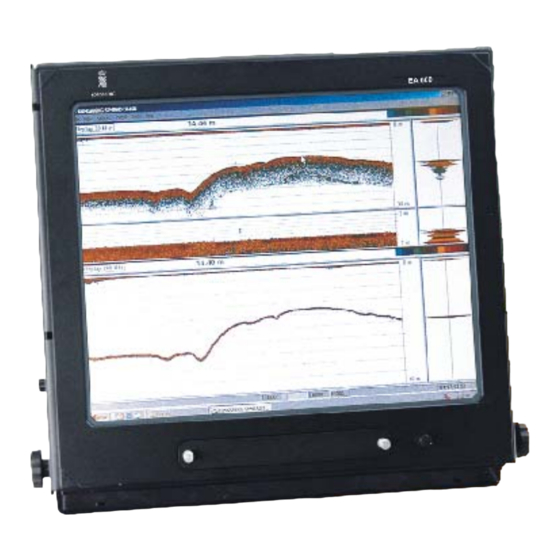
Introduction Operator Station The EA 600 is supplied with the HOS 192 Operator Station This is a 19-inch display with a built-in computer. Optionally, the smaller HOS 152 can be supplied. Earlier systems included the HOS 181 or HOS 151. -
Page 28: Ethernet Hub
Ethernet HUB When more than one General Purpose Transceiver is supplied, the EA 600 will be supplied with an Ethernet HUB. Several different switches are available. A standard commercial is HUB supplied with the echo sounder, unless a specific type is specified by the customer. -
Page 29: Hardware Installation
Hardware installation 2 HARDWARE INSTALLATION Introduction This chapter contains the necessary information for installation of the various units comprising the EA 600 echo sounder. Hardware items → Basic installation procedure (overview), page 20 → General Purpose Transceiver (GPT) installation, page 25 →... -
Page 30: Basic Procedure
EA 600 / Base version Basic procedure Purpose The basic installation procedure is presented here. Detailed technical information can be found in the next chapters. The applicable page references are made in the procedure. Parts configuration Check that you have received all parts required for the installation;... - Page 31 Hardware installation If only one GPT is used, you need a twisted pair cable with swapped receive and transmit wires. The cable is connected between the GPT and the echo sounder’s Operator Station. An Ethernet Hub is required if your system includes more than one General Purpose Transceiver.
-
Page 32: Parts And Configurations
EA 600 / Base version Parts and configurations Overview The EA 600 echo sounder is designed as a modular system. It supports a variety of configurations and frequency options. The EA 600 echo sounder is provided in several configurations. The basic configurations are: •... -
Page 33: Transceiver
GPT--S210(x)--H 210 kHz (x kW) GPT--S710(x)--H 710 kHz (x kW) ...where x identifies the output power: • EA 600: 1 to 2 (= 1 to 2 kW) Typical dual frequency configurations include: Identification Frequency and power GPT--S38(x)/S200(x)--H 38 kHz (x kW) & 200 kHz (x kW) GPT--S50(x)/S200(x)--H 50 kHz (x kW) &... -
Page 34: Display Unit
EA 600 / Base version • Other 3. party frequencies as 15 kHz, 33 kHz and 210 kHz are available and can be configured as single or dual combinations. Note Frequencies below 33 kHz for EA 400 has a max bottom range at 200 m. -
Page 35: General Purpose Transceiver (Gpt)
Hardware installation General Purpose Transceiver (GPT) Overview The GPT transceiver is a self-contained unit. It can be mounted anywhere onboard the vessel. It is recommended to mount the GPT as close to the transducer(s) as possible in order to minimise the electrical interference into the transducer cable. DSP-6X POWER General Purpose Transceiver... -
Page 36: Operator Station
EA 600 / Base version Operator Station A standard personal computer is used. Depending on the computer type (desktop integrated with LCD, tower or laptop), install the unit so that it is secure and able to withstand the shock, vibrations and movements experienced on a ship. -
Page 37: Printer
Hardware installation Printer Introduction Any Microsoft Windows® compatible printer may be connected to the EA 600 Processor Unit. The connection is made with a standard Centronics type parallel cable. Hardware installation Refer to the applicable printer documentation for hardware installation. Make sure that the printer is securely mounted to withstand the shock, vibrations and movements experienced on a ship. - Page 38 EA 600 / Base version On the third page, select HP in the manufacturers list, and HP DeskJet 970C in the printers list. Click Next to continue. - If a different printer make is installed, select the appropriate manufacturer and model. If the printer you have is not listed, refer to Software installation of unlisted printer.
-
Page 39: Software Installation Of Unlisted Printer
Hardware installation Software installation of unlisted printer If your new printer is not listed on the second installation page, observe the following procedure: On the second page, press the Have disk button. Insert the disk or CD ROM supplied with you printer, and identify the drive name for the installation program. -
Page 40: Transducer Installation
EA 600 / Base version 3 TRANSDUCER INSTALLATION Transducer location General A single answer to the question where to locate the transducer cannot be given. It depends very much on the vessel’s construction. However, there are some important guide lines. -
Page 41: Propeller Noise
Transducer installation layer is thin underneath the forward part of the vessel, and increases in thickness as it moves towards aft. If the sides of the hull are steep, some of the air bubbles in the boundary layer may escape to the sea surface along the vessel sides. It is our experience that a wide and flat bottom, with a rising angle less than around 13 degrees, is prone to giving air problems for the transducer. -
Page 42: Vessel Heave
EA 600 / Base version Bow thruster propellers are awful machines. When they are in operation, the noise and cavitation bubbles make the echo sounder useless, almost no matter where the transducer is installed. And when not in operation, the tunnel creates... -
Page 43: Summary
Transducer installation Summary Some of the above guide lines are conflicting, and each case has to be treated individually in order to find the best compromise. Generally the propeller noise is the dominant factor, and a recommended transducer location is in the fore part of the hull, with maximum distance from the bow equal to one third of the total length of the hull at the water line. -
Page 44: Ways Of Mounting The Transducer
EA 600 / Base version Ways of mounting the transducer Inclination of the transducer face Incline the transducer face approximately 2 degrees, so that the flowing water meets it directly. This assures laminar water flow. Mounting screws should not be extruding from the transducer, and the space around the screws could be filled with a compound or a locking ring. - Page 45 Transducer installation Figure 5 External mounting on wood or polyester hulls These transducers are mainly used on smaller vessels. A location approximately 0.5 m aside from the keel may be adequate for the passage of water between the keel and the transducer.
-
Page 46: Transducer Blister
EA 600 / Base version Transducer blister Other transducers are designed for installation into the hull or in a blister. In general, a blister installation is the recommended method. It brings the transducer below the boundary layer. A blister is illustrated below. - Page 47 Transducer installation Large diameter transducers must be fitted with a horizontal support bar. This bar can then be secured to the mounting ring using threaded rods. → Refer to figure 6. The transducer cable penetrates the hull in a stuffing tube. Leave an adequate loop of the cable behind the transducer for easy mounting or removal of the transducer.
-
Page 48: In A Box Keel
EA 600 / Base version In a box keel Vessels with a box keel may use this for transducer installation. The box keel is already the deepest part of the vessel. If the box keel is too narrow to accommodate the transducer, it can be widened, either symmetrically or to one side only. - Page 49 Transducer installation Hull Figure 10 Retractable unit hull unit with transducer Keel Transducer 857-164688 / E...
-
Page 50: Centre Board
EA 600 / Base version Centre board The use of a centre board with the purpose of stabilising the vessel is well known. A centre board is also a superior platform for transducers. Such instrument keels have been built, mainly on research vessels, with a length of 3 m, protruding also 3 m below the hull, see the figure below. -
Page 51: Flush Mounting In A Steel Tank
Transducer installation Flush mounting in a steel tank Flush mounting is used on very large vessels with a hull so deep that no air bubbles are found below the hull, and on vessels operating in shallow harbours or waters, where a protruding blister can not be accepted. -
Page 52: Behind A Protective Acoustic Window
Vessels operating in arctic waters need special attention on transducer installation. Floating blocks of ice may damage even a flush mounted transducer face. For this situation Kongsberg Maritime offers ‘’arctic tanks’’ in different sizes. The transducer shown in the figure below is mounted inside the tank behind a strong acoustic window which could be made of polycarbonate. -
Page 53: Inside The Hull
The loss varies with the distance between transducer face and the hull. The best result is obtained when the distance is half a wavelength. Consult Kongsberg Maritime for advice. In addition to the loss, the beam pattern is degraded, because a larger area of the hull is set into vibrations. - Page 54 EA 600 / Base version Echo Figure 15 Example sounder steel tube arrangement Steel tube Stuffing tube Rubber gasket Washers Packing nipple (CD1995) The tube should be unbroken and watertight from the transducer to above the water line. From there, openings or a junction box can be installed to facilitate drawing of the cable, or to add a cable extension.
- Page 55 Transducer installation Most Kongsberg Maritime transducers are delivered with 20 m cable. Excess cable can be cut off, or an extension cable can be added. This is possible because all Kongsberg Maritime transducers have a built-in transformer for tuning and matching to the cable impedance of 75 Ohms.
-
Page 56: Approved Anti-Fouling Paints
EA 600 / Base version Approved anti-fouling paints This is Kongsberg Maritime’s list of approved antifouling paints on polyurethane transducer housing. From Jotun Paints, Sandefjord Norway: • Antifouling Seamate HB 33 • Antifouling Seamate HB 66 • Antifouling Seamate HB 99 •... -
Page 57: Description And Maintenance
GPT description and maintenance 4 GENERAL PURPOSE TRANSCEIVER (GPT) DESCRIPTION AND MAINTENANCE Description and main functions Overview The GPT contains transmitter and receiver electronics. This chapter provides the following information: → Description and main functions, page 47. → GPT outline, page 48. →... -
Page 58: Gpt Drawing
EA 600 / Base version GPT drawing The basic GPT outline dimensions are shown in the diagram below, note that the illustration is not draw to scale. Unit body Width 284 mm Unit body Depth 246 mm (CD5167b/GIF) Unit body Height... -
Page 59: Circuit Boards And Modules
GPT description and maintenance Circuit boards and modules The GPT holds several circuit boards and two power supplies. All connections are made on the front panel. I/O card DSP-6x Power supply DC fuse General Purpose Transceiver POWER +12V - 12V Transducer Fuse 10A 115-230 VAC... -
Page 60: Gpt - Theory Of Operation
EA 600 / Base version GPT - Theory of operation Overview This chapter presents a functional description of the GPT. The GPT transceiver cabinet houses one or two TRX transmitter/receiver boards, a DSP signal processor board, an IO board handling various interface signals and a Power board. -
Page 61: Simplified Block Diagram
GPT description and maintenance Simplified block diagram The GPT holds several circuit boards and two power supplies. Block Diagram GPT Power boards Power pcb/Vicor DSP - 6x board I/O board 1 or 2 TRX board TRX1 TRX2 TRX3 TRX4 T R X 4 T R X 3 T R X 1 T R X 2... -
Page 62: Circuit Board Descriptions
EA 600 / Base version Circuit board descriptions Overview This chapter describes all the circuit boards and modules in the EA 600 GPT. A functional description with a block diagram is provided, as well as the facilities provided for maintenance. 857-164688 / E... -
Page 63: Digital Signal Processing Board, Dsp-6X
GPT description and maintenance Digital Signal Processing board, DSP-6x Purpose and description The DSP-6X is a general-purpose data acquisition, control and signal processing microcomputer board. It is targeted for high performance echo sounder applications. The board is remote controlled by a host via Ethernet under the TCP/IP/UDP protocol. - Page 64 EA 600 / Base version S1: indicate various error states S2: indicate various error states Below is a list of the different settings: • At power up or reset a flash sequence of 0,1,2,3,0 (S2 MSB, S1 LSB) means OK •...
-
Page 65: Trx Board
GPT description and maintenance TRX board Purpose and description The transmitter/receiver (TRX) board contains a full bridge 1 or 2 kW transmitter, a high precision receiver, a 12 bit AD converter and digital control circuitry. The transducer connector is located at the top of the board. Transmitter commands and sample data are digitally communicated via the address/data-bus at the bottom of the board. -
Page 66: I/O Board
EA 600 / Base version I/O board Purpose and description The I/O board is used to control the dual high voltage power supply residing on the POWER board. In addition it provides the external interface to sensors and input output signals. A PLD... -
Page 67: Gpt Power Supply
GPT description and maintenance GPT Power supply Purpose and description The GPT power module generates all internal voltages needed by the GPT transceiver. The power module consists of a printed circuit board with front plate and an external DC-DC switching converter. - Page 68 EA 600 / Base version How it works The converter operates at a switching frequency near 1 MHz, and its efficiency is approximately 80%. The mains converter section accepts input voltages from 95 to 265 Vac and alternation frequencies from 50 to 400 Hz.
-
Page 69: Maintenance On The Gpt
GPT description and maintenance Maintenance on the GPT The GPT transceiver is a small multi-configuration self-contained unit that can be mounted anywhere on board the vessel. Typically, it is mounted near the transducer in order to minimise electrical interference into the transducer cable. The GPT transceiver cabinet houses one or two TRX transmitter/receiver boards, a DSP signal processor board, an IO board handling various interface signals and a Power board. - Page 70 EA 600 / Base version The mains socket contains two 2 A fuses. Standard slow-acting types should be used. The Power board converts the 115-230 VAC input to a +12 VDC which is available via connectors at the front of the board. All other internal voltages inside the GPT are generated from this +12 VDC.
- Page 71 GPT description and maintenance Note In order to prevent electrical noise pickup along the transducer cable the screens must only be connected to chassis transducer plug! To chassis TD plug (CD 6761) Dual Frequency Side Scan 1+1 kW. This GPT configuration includes two transmitter/receiver boards.
- Page 72 EA 600 / Base version Pitch + Pitch - Roll + Roll - HeaveIn+ HeaveIn- Temp. In Hi Temp. AGND +12V dc Ground -12V dc Ground +5V dc Ground Not used Ground New line in Ground Event in Remote in...
- Page 73 GPT description and maintenance Ethernet TP Connector. The newer Twisted Pair interface is also provided; IEEE 802.3 compliant 10 Mbit/s Ethernet. This interface includes differential signals for transmit and receive. Auxiliary Connector. The I/O board contains a 25-pin female Delta connector handling various external interface signals. An analogue heave sensor can be connected to pins 3 and 16, 1 and 14 is for pitch and 2 and 15 is for roll.
- Page 74 EA 600 / Base version DSP6x board Status Lamps. S1 and S2 displays a two bit binary number; S2 displays bit 1 and S1 displays bit 0. Hence, S2 on and S1 off corresponds to the quantity 10 binary or 2 decimal.
-
Page 75: Replacement Procedures
Replacement procedures 5 REPLACEMENT PROCEDURES Introduction Overview This chapter presents the basic procedures for disassembly and reassembly of the replaceable parts in the EA 600 system. 857-164688 / E... -
Page 76: Tools Required
EA 600 / Base version Tools required A standard tool set is required to perform the removal and replacement of the modules. This tool set should contain the following tools: • Cabinet key (IP 55 cabinet) • Standard screwdrivers in different widths and lengths •... -
Page 77: General Purpose Transceiver (Gpt) Procedures
Replacement procedures General Purpose Transceiver (GPT) procedures Overview The Line Replaceable Units (LRUs) in the GPT are: • TRX transmitter and transceiver board(s) • DSP-6x • I/O card • Power supply • Vicor power Other devices: • AC mains fuse, 2A slow •... -
Page 78: Power Supply
EA 600 / Base version Power Supply Introduction How to open the GPT is described under the Disassembly procedures of the Circuit boards and modules. Disassembly procedure Switch off the circuit breaker. Unbolt the unit. It is mounted with four captive-bolts so they cannot fall out. -
Page 79: Cable Layout
Cable layout 6 CABLE LAYOUT Introduction This chapter describes the general installation requirements for the EA 600 system cables. These instructions must be used together with the applicable cable plan(s). Note All cable connections and installation must be made in accordance with the guidelines laid down by the vessel’s... -
Page 80: Cable Plans And Specifications
EA 600 / Base version Cable plans and specifications Configurations The system cables are identified in following cable plans. Each cable is identified with a cable number (Cx). Further information about the cable (connections and specifications) may be found on the referenced page(s). -
Page 81: Processing Unit
Cable layout Processing Unit Specifications The cables shown and specified here are those used when the EA 600 is implemented with a separate Processing Unit. Power C1008 C1006 supply AC power Ship's GND (Optional) C1009 C1001 (CD24215) AC power VGA cable... - Page 82 C1007 and C1017 available, one Ethernet line is used to communicate directly with the GPT, while the other connects the EA 600 to the computer. Both cables are terminated with RJ45 plugs, and can be supplied by the installation shipyard.
- Page 83 Cable layout C1015 / C1016 - USB These are two standard USB cables. Both are optional, and the cables are supplied by Kongsberg Maritime when applicable. → Cable details, page 116. Note that commercial “RS-232 to USB” converters may also be put to use if the number of available serial lines is too small.
-
Page 84: Hydrographic Operator Station
EA 600 / Base version Hydrographic Operator Station Specifications The cables shown and specified here are those used when the EA 600 Operator Station is implemented with a HOS 152 or HOS 192 Hydrographic Operator Station. C1008 AC power VGA (slave display) C1001... - Page 85 Ethernet network GLAN. Both cables are terminated with RJ45 plugs, and both must be supplied by the installation shipyard. One short LAN cable is supplied by Kongsberg Maritime for connection computer and GPT. Failure to use separate network adapters will cause a heavy traffic load on the common network.
- Page 86 25-pin connector, cable details, page 109. C1014, C1015, C1016 and C1018 - USB These are four standard USB cables. Both are optional, and the cables are supplied by Kongsberg Maritime when applicable. → Cable details, page 116. Note that commercial “RS-232 to USB” convertes may be put to use if the number of available serial lines is too small.
- Page 87 Cable layout Figure 28 Connector and switch on the operator station’s front 857-164688 / E...
-
Page 88: General Purpose Transceiver (Gpt)
General Purpose Transceiver (GPT) Specifications The cables shown and specified here are those used when the EA 600 is implemented with one or two stand-alone General Purpose Transceiver (GPT) units. The cable plan is shown on the next pages. Note that the 15-pin network connector on the GPT is not used. - Page 89 Transceiver (GPT) no.1 Transceiver (GPT) no.2 SIMRAD SIMRAD C1224 C1220 Ground AC Power C1324 C1320 Ground AC Power Junction Junction Box (1:1) Box (1:1) C1433 C1533 Transducers Transducers Figure 30 EA 600 cable plan - Dual GPT 857-164688 / E...
- Page 90 EA 600 / Base version Connectors The following connectors are located on the rear side of the General Purpose Transceiver (GPT) unit. Auxiliary connector Network Transducer connector connector 10A Fuse +12 Vdc sockets Use only with a 250V fuse Employer uniquement avec...
- Page 91 Cable layout C1221 - AC Power to Ethernet Hub/switch An Ethernet Hub or switch is required if you need to use more than one General Purpose Transceiver (GPT), or if you wish to connect the echo sounder system to an existing network. Any commercial 100 MHz Hub/switch may be used.
- Page 92 EA 600 / Base version C1229 / C1234 - Synchronization of GPT 1 and GPT 2 This cable is used to connect the GPT to an external system for synchronization purposes. The cable must be provided by the shipyard. →...
-
Page 93: Gpt Cabinet
Specifications The cables shown and specified here are those used when the EA 600 is implemented with a GPT Cabinet for IP55 protection. The cabinet may contain one or two General Purpose Transceiver (GPT) units and an Ethernet switch. All internal cabling in the cabinet is made by the manufacturer. - Page 94 Digital ground C1229 C1228 Synchronisation GPT 1 Remote on/off C1234 C1222 Synchronisation GPT 2 DC output Figure 32 EA 600 cable plan - GPT Cabinet C1225 - Digital ground Standard grounding cable, must be provided by the shipyard. 857-164688 / E...
- Page 95 Cable layout → Cable details, page 120. C1226 - New line annotation (trigger input) This input is referenced to digital ground. The cable must be provided by the shipyard. → Cable details, page 120. C1227 - Event annotation (trigger input) This input is referenced to digital ground.
- Page 96 EA 600 / Base version The transducer cables are provided by the manufacturer. The standard transducer cable supplied is 15 to 20 meters long. → Cable details, page 126. C1234 - Synchronisation of GPT2 This cable must be provided by the shipyard.
-
Page 97: External Interfaces
Cable layout External interfaces Overview • Navigation (GPS) interface (NMEA) • Annotation text input (NMEA) • Depth telegram output (NMEA) • Heave sensor input Navigation (GPS) GPS (Global Positioning System) receivers output NMEA 0183 telegrams containing geographical latitude and longitude. The defined communication parameters are: •... -
Page 98: Heave Sensor
• The $SDDPT telegram contains the depth below the transducer and the distance between the transducer and the waterline. The EA 600 can also output the EA 500/EK500 compatible depth telegrams; D1, D2 etc. Output for Atlas echo sounders are also provided. -
Page 99: External "Event" Triggering
Cable layout Open the Printer Setup dialogue box. Enter the selected printer. External “Event” triggering An external switch may be connected to the General Purpose Transceiver (GPT) to trigger Events manually. Alternatively, the trigger can be a negative pulse. External “New line number” triggering An external switch may be connected to the General Purpose Transceiver (GPT) to trigger “New line number”... -
Page 100: External Triggering
Slave operation. Master system When the EA 600 system is set up to operate as a Master in a system, the TrigOut signal from the GPT Auxiliary connector must be connected to the external trigger input on the other hydroacoustic system(s). -
Page 101: Slave System
Connect the ground wire to one of the Ground pins (18-22). Note If the EA 600 system comprises more than one GPT unit, the external trigger must be connected in parallel to every GPT. → The cable and connections to the GPT is shown on page 123. -
Page 102: Spare Parts
Overview This chapter contains an illustrated presentation of the spare parts available for the EA 600 single beam echo sounder. All the parts are not listed her, only those defined as Line Replaceable Units (LRU) to be changed by the on-board maintenance personnel. -
Page 103: Gpt Spare Parts
Spare parts GPT spare parts The line replaceable units in the EA 600 GPT are: • Circuit boards • Power supply The spare parts in the GPT are those circuit boards used in the chassis. I/O card DSP-6x Power supply... - Page 104 EA 600 / Base version Fig.33 382--200002 Power supply 26.09.02 Fig.33 382--200889 Vicor power supply 26.09.02 Commercial item 857-164688 / E...
-
Page 105: Drawing File
This chapter contains cable details and installation drawings. Installation drawings If required, certain drawings may be supplied on AutoCad format. To order, contact Kongsberg Maritime and refer to the drawing number in the bottom right corner of the frame. →... - Page 106 EA 600 / Base version DSP-6X POWER General Purpose Transceiver +12V -12V Fuse 10A Transducer 115-230 VAC Fuse 2A Cut-out 298 Utkapp 298 For panel mounting, use countersunk head screws: M5 machine screws, 4.8 mm plate screws or 5 mm wood screws.
- Page 107 Drawing file Available for service Adkomst for vedlikehold Mounting examples Monteringseksempler Hints for installation: - Remember the earth connection on the rear panel. - All other connections are made on the front panel. - Try to make the wiring simple. - Remember to make room for maintenance.
- Page 108 EA 600 / Base version 415 mm 400 mm 405 mm 342 mm ø 10.2 mm (4 holes) 834-215556 Page 1 of 1 GPT Cabinet, Outline dimensions (CD5979) Rev.A 857-164688 / E...
- Page 109 Drawing file Wiring acc. to T-568 B White To Display and Pair 1 Blue White Pair 2 Processor Unit Orange White Pair 3 Green White Pair 4 Brown Ship's cable 1 2 3 4 5 6 7 8 8-pin modular socket (Regulator) Ethernet HUB...
- Page 110 EA 600 / Base version ø8.5 EA Transducer Switch Unit 834-223074 Page 1 of 1 outline dimensions CD24104 Rev.A 857-164688 / E...
- Page 111 Drawing file EA Transducer Connection Unit 834-223080 Page 1 of 2 interconnection diagram CD24105 Rev.B 857-164688 / E...
- Page 112 EA 600 / Base version EA Transducer Connection Unit 834-223080 Page 2 of 2 interconnection diagram CD24105 Rev.B 857-164688 / E...
- Page 113 Drawing file ø8.5 EA Transducer Connection Unit 834-223046 Page 1 of 1 outline dimensions CD24103 Rev.A 857-164688 / E...
- Page 114 EA 600 / Base version Not to scale Integreated 15.1’’ Display computer Max. 60 Ø7x4 Cut-out Cut-out For best results use four screws (order number: 599-200984) and four nuts ( order number: 599-200986) when mounting the unit in panels with a thickness of 22 mm or less.
- Page 115 Drawing file 834-223084 Page 1 of 1 HOS 152 Dimensions and panel cut-out (Cd25002) Rev.A 857-164688 / E...
- Page 116 EA 600 / Base version Not to scale 18.1’’ Display Integreated computer Max. 60 Ø7x4 Cut-out For best results use four screws (order number: 599-200984) and four nuts ( order number: 599-200986) when mounting the unit in panels with a thickness of 16 mm or less.
- Page 117 Drawing file 834-223088 Page 1 of 1 HOS 192 Dimensions and panel cut-out (Cd25003) Rev.A 857-164688 / E...
- Page 118 EA 600 / Base version Top view HP KAYAK Front view HP KAYAK 834-215692 Page 1 of 1 HP Kayak outline (CD6007) Rev.A 857-164688 / E...
-
Page 119: Generic Rs-232 Serial Line (Dce)
Drawing file Generic RS-232 serial line (DCE) This cable described the pin configuration for an RS-232 interface. The Data Circuit terminating Equipment (DCE) end is shown. Shield Received data (Rx) 25-pin D-sub connector Transmitted data (Tx) Original and complete RS-232 signal definition shown. -
Page 120: Generic Rs-232 Serial Line
EA 600 / Base version Generic RS-232 Serial line This cable comprises a multi-purpose serial line. It provides interface with any peripheral unit. One end of the cable connects to the local unit (DTE) with a 9-pin ’D’ connector, while the other connects to the peripheral (DCE) as described in the peripheral unit’s documentation. -
Page 121: Standard Ac Power Cable
Drawing file Standard AC power cable This cable is a standard three-wire power cable. It is commercially available in standard lengths, or may be produced locally to suit the specific installation needs. The instrument end is terminated in a standard IEC female socket, while the other end is terminated in a plug suitable for the local standard. -
Page 122: Emc Ground
EA 600 / Base version EMC ground This cable is used to connect the system unit to the ship’s ground. Note that this cable must be as short as possible. Units's ground tag Ships' ground Ship's ground W311 / Rev B... -
Page 123: Battery
Drawing file Battery This cable is used to connect a battery to the system. Red plug and red socket is normally used for positive (+). Black plug and black socket is normally used for negative (-). Banana plugs and sockets Battery Battery W319 / Rev. -
Page 124: Ethernet With Rj45 Plugs (Screened)
EA 600 / Base version Ethernet with RJ45 plugs (screened) This cable contains the Ethernet connection. RJ45 plugs are used to terminate the cable. Note that these plugs must be screened to comply to EC rules. Pin 8 Pin 1... -
Page 125: Standard Vga Cable
Drawing file Standard VGA cable This is a standard display cable used to connect the video signals. The cable is normally physically fastened to the display unit, and it is provided with the plug(s) readily attached. 857-164688 / E... -
Page 126: Standard Usb Cable
EA 600 / Base version Standard USB cable This is a standard commercial USB cable terminated with A and B plugs in either ends. The cable can be used for a variety of external devices. The order number provided is for a 4.5 m cable. -
Page 127: Keyboard Cable
Drawing file Keyboard cable This is a standard keyboard cable. In most cases, the cable is physically connected to the keyboard. It is terminated in a plug suited to fit the computer. Several keyboard types are available for different languages and hardware platforms. -
Page 128: Mouse Or Pointing Device Cable
EA 600 / Base version Mouse or pointing device cable This is a standard mouse cable. It is physically connected to the mouse. It is terminated in a plug suited to fit the computer. Note On Unix work stations, the mouse is normally connected to the keyboard. -
Page 129: Printer Cable
Drawing file Printer cable This is a standard printer cable. It is terminated in the computer’s parallel port. The socket on the rear side of the computer is normally a 25-pin female D-connector. Parallel port 25-pin connector D-connector (IEEE 1284-A) Strobe Data 0 Data 1... -
Page 130: Gpt Cabinet Interface Cables
EA 600 / Base version GPT Cabinet interface cables These are the cables used to interface the GPT Cabinet. Note that Ethernet and transducer cables are described separately. Screen Spare Spare Spare Digital GND Digital GND +5VDC +12VDC -12VDC Trig in -(GPT 2) - Page 131 Drawing file Specifications for each of the cables (except AC power cables): Conductors N x 0.5 mm2 Screen Overall braided Voltage 60 V Max.diameter Set by the plugs Specifications for AC power cable: Conductors 3 x 2.5 mm2 Screen Separate conductor Voltage 750 V Max.diameter...
-
Page 132: Remote On/Off
EA 600 / Base version Remote on/off This cable is used to connect a remote on/off switch to the General Purpose Transceiver (GPT). The switch can be located in a separate box, or incorporated on a common switch panel. Reset and... -
Page 133: Gpt Remote Synchronisation
Drawing file GPT Remote synchronisation This cable is used to connect the General Purpose Transceiver (GPT) to an external system for synchronisation purposes. SIMRAD 25-pin D-sub connector TrigOut(+) Auxiliary TrigIn(+) connector (female) TrigOut(-) TrigIn(-) Several transceivers may be triggered from an external system by connecting the TrigIn pins in parallel. -
Page 134: Motion And Temperature Sensors
EA 600 / Base version Motion and temperature sensors This cable is used to connect the General Purpose Transceiver (GPT) to external motion and temperature sensors. SIMRAD GPT 25-pin D-sub connector Pitch(+) Roll(+) Heave(+) Pitch(-) Roll(-) Auxiliary connector Heave(-) (female) -
Page 135: New Event And Line Number
Drawing file New Event and Line number This cable is used to connect the General Purpose Transceiver (GPT) to two external buttons for generation of new “Events” and “Line numbers”. SIMRAD 25-pin D-sub connector New line number Auxiliary connector (female) New Event The cable screen is connected Use a small spring loaded button, or... -
Page 136: Transducer(S)
The cable between the junction box and the transceiver must then be supplied by Kongsberg Maritime, and this must be the same type as used on the transducer(s). - Page 137 2 x N mm2 Screen Overall braided Voltage 600 V Max.diameter The conductor diameter “N” depends on the chosen transducer. Normal value for single beam transducers is 1.5 mm . Special transducer cable is available from Kongsberg Maritime. 857-164688 / E...
- Page 138 2 x N mm2 Screen Overall braided Voltage 600 V Max.diameter The conductor diameter “N” depends on the chosen transducer. Normal value for single beam transducers is 1.5 mm . Special transducer cable is available from Kongsberg Maritime. 857-164688 / E...
- Page 139 3 x N mm2 or 2 x N mm2 Screen Overall braided Voltage 600 V Max.diameter The conductor diameter “N” depends on the chosen transducer. Normal value for single beam transducers is 1.5 mm . Special transducer cable is available from Kongsberg Maritime. 857-164688 / E...
- Page 140 2 x 2 x N mm2 Screen Overall braided Voltage 60 V Max.diameter The conductor diameter “N” depends on the chosen transducer. Normal value for single beam transducers is 1.5 mm . Special transducer cable is available from Kongsberg Maritime. 857-164688 / E...
- Page 141 4 x 2 x N mm2 Screen Overall braided Voltage 600 V Max.diameter The conductor diameter “N” depends on the chosen transducer. Normal value for single beam transducers is 1.5 mm . Special transducer cable is available from Kongsberg Maritime. 857-164688 / E...
- Page 142 2 x 2 x N mm2 Screen Overall braided Voltage 60 V Max.diameter The conductor diameter “N” depends on the chosen transducer. Normal value for single beam transducers is 1.5 mm . Special transducer cable is available from Kongsberg Maritime. 857-164688 / E...
- Page 143 Drawing file Cable colours on split beam transducers Note that the cables from the transducer may be supplied in different colours. The following colours may be used: Channel Shown in W802- -3 Alt.A Alt B 857-164688 / E...
- Page 144 EA 600 / Base version Upper plug case Plug fastening ring Contact body Retaining ring Outer screen and inner screen braid wire untaped and spread out under washer Outer screen together with inner screen. Drain wire, fold back over jacket and temporary fastened with tape.
-
Page 145: Appendices
Appendices 9 APPENDICES Overview This chapter holds the following appendices: → Equipment handling, page 136 → Basic cabling requirements, page 147 → Cable gland assembly procedure, page 150 857-164688 / E... -
Page 146: Equipment Handling
Unless otherwise stated in the accompanying documentation, electronic, electro-mechanical and mechanical units supplied by Kongsberg Maritime can be transported using all methods approved for delicate equipment; (by road, rail, air or sea). The units are to be transported in accordance with general or specific instructions for the appropriate unit(s), using pallets, transport cases, or carton boxes as appropriate. -
Page 147: Initial Preservation
Appendices Lifting A heavy crate will normally be marked with its weight, and the weights of other cartons or crates will normally be entered on the packing list. • Always check the weight of a crate before attempting to lift •... - Page 148 EA 600 / Base version The crates must not be placed on top of each other, unless specific markings permit this. The crates must not be placed directly on a dirt-floor. Do not open the crate for inspection unless special circumstances permit so.
-
Page 149: Inspection And Unpacking
• If any units are damaged, prepare an inspection report stating the condition of the unit and actions taken. Describe the damage and collect photographic evidence if possible. Send the inspection report to Kongsberg Maritime as soon as possible. • If the units are not damaged, check the humidity absorbing material. - Page 150 EA 600 / Base version General unpacking procedure Normal precautions for the handling, transportation and storage of fragile electronic equipment must be undertaken. Note If the unit is not to be prepared for immediate use, you may consider storing it unopened in its original packing material.
- Page 151 Appendices Electronic and electro-mechanical units Caution Beware of the dangers of Electro-Static Discharge (ESD) both to yourself and to the equipment, when handling electronic units and components. Refer to the precautions starting on page 145. Electronic and electro-mechanical units will normally be wrapped in a clear plastic bag.
-
Page 152: Storage
EA 600 / Base version Re-packing If the unit is not to be installed immediately, re-pack it in its original packing material to prevent damage in the intervening period. → Refer to the information on page 144. Storage Pre-installation storage The equipment should be stored in its original transportation crate until ready for installation. - Page 153 Appendices Cleaning cabinets If a cabinet has been exposed to salt atmosphere while it was in use, it must be thoroughly cleaned both internally and externally to prevent corrosion. • Wipe the cabinet externally using a damp cloth and a little detergent.
-
Page 154: Re-Packing
Cables Wipe clean all exposed cables, and check for damage. If a cable shows signs of wear or ageing, contact Kongsberg Maritime for advice. Internal batteries If the unit contains batteries, these may discharge slowly during storage. -
Page 155: Esd Precautions
Appendices • Small units must be protected from damp by being placed within a plastic bag at least 0.15 mm thick. An appropriate quantity of desiccant material should be placed inside this bag, and the bag sealed. The sealed unit must then be placed in an appropriate carton or crate, and supported in the container by appropriate shock-absorbing insulation (polystyrene foam chips etc.). -
Page 156: Temperature Protection
EA 600 / Base version Caution If, for any reason, it is necessary to move the circuit board or components from the conductive service mat, they must be placed in an approved anti-static transportation container (e.g. static shielding bag) before transportation. -
Page 157: Basic Cabling Requirements
Appendices Basic cabling requirements Cable trays All permanently installed cables associated with the system must be supported and protected along their entire lengths using conduits and/or cable trays. The only exception to this rule is over the final short distance (max. 0.5 metre) as the cables run into the cabinets/units to which they are connected. - Page 158 EA 600 / Base version Radio Frequency interference All cables that are to be permanently installed within 9 m (30 ft) of any source of Radio Frequency (RF) interference such as a transmitter aerial system or radio transmitters, must, unless shielded by a metal deck or bulkhead, be adequately screened by sheathing, braiding or other suitable material.
- Page 159 Appendices Cable connections All cable connections are shown on the applicable cable plan and interconnection diagrams. Where the cable plan shows cable connections outside an equipment box outline, the connections are to be made to a plug or socket which matches the plug or socket on that particular item of equipment.
-
Page 160: Cable Gland Assembly Procedure
There are many different types of cable gland on the market. This procedure describes the types used (now and previously) as standard in the units manufactured by Kongsberg Maritime. The cable glands are not supplied with the system. Even though the cabinets from Kongsberg Maritime may be prepared for specific types, the installation shipyard will be responsible for selecting cable gland types and installing them. -
Page 161: Securing And Terminating The Cables
Appendices Depending on whether the cable has already been installed in conduits, either. a (installed) measure the maximum length of cable required to reach from the final cable clip outside the cabinet to the terminal blocks inside the cabinet, add 20 cm, then remove the excess cable, b (loose cable) measure the maximum length of wire required to reach from the cable gland to the terminal... -
Page 162: Multi-Diameter Modules
EA 600 / Base version Multi-diameter modules Multi-diameter cable glands are now available from several sources, and these types are becoming increasingly popular due to ease of use. Only a brief description of the system will be presented here, further information with technical specifications and installation descriptions must be obtained from the manufacturer(s). - Page 163 Appendices Figure 36 Multi-diameter system - general procedure Once the cables are through, each cable is secured with a square module, which is adjusted to fit the cable’s outer diameter. When the required number of modules are installed, the assembly is tightened with a compression unit. This system is available with a large number of various modules and compression units, and it will also comply with screening and EMC requirements.
-
Page 164: Standard Type
EA 600 / Base version Standard type Ensure that all the cables to be connected are completely isolated from any power sources. - Switch off and remove the supply fuses from any units or systems into which the cables are already connected. - Page 165 Appendices Note The cable’s outer insulation will extend into the cable gland to a point approximately 5 mm outside the outer surface of the cabinet wall into which the cable gland is secured. Take care not to damage the screening, carefully remove the outer insulation from the required cable length.
-
Page 166: Additional Type
EA 600 / Base version Once all the system cables are connected and checked: Take the appropriate safety measures, then replace the fuses and apply power to the system. Perform a system test to ensure the installation has been conducted successfully. - Page 167 Appendices Slide the metal washers, the rubber gasket and the compression nut onto the cable in the order indicated in the figure. → Refer to figure 40. Bend the screen over the compression cone. Push the compression conne, the washers and the rubber sealing washer into the cable gland body.
- Page 168 EA 600 / Base version 857-164688 / E...
- Page 170 E 2006 Kongsberg Maritime...
Need help?
Do you have a question about the EA 600 and is the answer not in the manual?
Questions and answers