Kongsberg EK80 Reference Manual
Wide band scientific echo sounder
Hide thumbs
Also See for EK80:
- Installation manual (354 pages) ,
- Instruction manual (88 pages) ,
- Quick start manual (15 pages)
Table of Contents
Advertisement
Quick Links
Advertisement
Table of Contents
Troubleshooting

Subscribe to Our Youtube Channel
Related Manuals for Kongsberg EK80


Summary of Contents for Kongsberg EK80
- Page 1 REFERENCE MANUAL EK80 kongsberg.com/ek80...
- Page 2 PUBLIC Kongsberg EK80 Wide band scientific echo sounder Reference Manual Release 23.6.0 395234/J August 2023 © Kongsberg Maritime AS...
- Page 3 The information contained in this document remains the sole property of Kongsberg Maritime AS. No part of this document may be copied or reproduced in any form or by any means, and the information contained within it is not to be communicated to a third party, without the prior written consent of Kongsberg Maritime AS. Warning The equipment to which this manual applies must only be used for the purpose for which it was designed.
-
Page 4: Table Of Contents
Support information ......................34 GETTING STARTED ..............35 Starting normal operation ..................... 36 Turning on the EK80 system ..................36 Getting to know the user interface ................37 Checking transceiver and transducer settings ............. 39 Selecting Normal mode to start pinging..............41 Switching between ADCP and echo sounder operation.......... - Page 5 Information pane ......................74 Menu system........................ 78 Working with depth layers................... 79 Setting up the EK80 Wide band scientific echo sounder for the first time ......82 Setting up summary..................... 82 Installing the EK80 operating software............... 84 Turning on the EK80 system for Passive mode ............85 Obtaining and installing the software license..............
- Page 6 Reference Manual Selecting Advanced Sequencing mode ...............116 Verifying that the bottom is correctly detected ............117 Defining the ping (transmission) modes..............119 Transmitting single pings ..................120 Transmitting with fixed-time intervals ..............121 Switching between ADCP and echo sounder operation..........122 Opening the context-sensitive online help ..............123 Controlling the gain and range settings ................
- Page 7 Kongsberg EK80 Capturing the display presentation in video files..............161 Capturing the display presentation in a video file ............. 161 Selecting where to save the video files..............162 Setting up the echogram presentation ................. 163 Selecting which echogram type to use ..............163 Selecting echogram views on the bottom bar............
- Page 8 Reference Manual Creating a new depth layer ..................202 Modifying the properties of an existing depth layer ..........205 Deleting a depth layer....................206 Monitoring the numerical information in a depth layer ..........208 Exploring water velocities using ADCP ................210 Opening the ADCP (acoustic Doppler current profiler) information pane ....
- Page 9 Restoring the locations and sizes of the views ............258 Rearranging the tabs at the bottom of the EK80 presentation........259 Creating personalized views by adding a new tab to the bottom of the EK80 presentation......................260 Removing personalized presentations ............... 261 Defining settings related to user preferences and individual customizing......
- Page 10 Exporting sensor data to a peripheral system ............305 Synchronizing the EK80 by means of a serial port ........... 306 Synchronizing the EK80 system by means of the Auxiliary port ......309 Setting up the interface between the EK80 and the Kongsberg TD50.......311 Installing transducers and transceiver channels in the user interface .........
- Page 11 ........................345 Synchronization sequences..................345 Synchronizing the EK80 by means of a serial port ........... 346 Synchronizing the EK80 system by means of the Auxiliary port ......349 Selecting synchronization mode................351 Serial port synchronization signalling ............... 353 Auxiliary port synchronization signalling ..............353 Selecting synchronization port ..................
- Page 12 Reference Manual Measuring noise in passive operating mode.............. 397 Making a noise/speed curve to determine vessel noise ..........399 Collecting and checking noise data ................401 CALIBRATION PROCEDURES............ 405 USER INTERFACE..............406 User interface familiarization ..................... 407 Top bar ..........................409 Top bar overview.......................
- Page 13 Trawl Line description ....................498 Vertical Tick description.................... 499 White Line description ....................500 Biomass Line description ..................501 The EK80 menu system ...................... 503 Bottom bar description......................505 Replay bar description ......................506 Working with depth layers ....................507 Screen capture browser description ..................
- Page 14 Reference Manual FUNCTIONS AND DIALOG BOXES..........539 Main menu: functions and dialog boxes................540 User Settings dialog box.................... 540 Range function ......................543 Start Range function ....................544 Minimum Level function................... 546 Operation menu: functions and dialog boxes ..............549 Operation function.....................
- Page 15 Kongsberg EK80 Beam Direction function ................... 597 New Layer dialog box ....................598 Layer Properties dialog box ..................603 Delete Layer function ....................608 Bottom Detection dialog box ..................609 Single Target Detection dialog box ................611 Information Pane Options dialog box ............... 615 Combined View Settings ...................
- Page 16 Reference Manual Ensemble page......................680 Sequence page ......................681 Pages in the Installation dialog box ..................684 Transducer Installation page..................685 Transceiver pages ...................... 692 Transceiver Installation page..................693 Transceiver IP Address page ..................702 Sensor Installation page..................... 705 Sensor Configuration page ..................710 Synchronization page ....................
- Page 17 Kongsberg EK80 Sv(f) page ........................813 TS(f) page........................814 ADCP page........................ 814 External Sensors page ....................817 Pages in the Echogram dialog box..................819 Lines page........................819 Echogram page ......................822 Horizontal Axis page....................826 Pages in the ADCP View Settings dialog box ..............827 Horizontal Axis page....................
-
Page 18: About This Manual
EK80 system. Target audience This publication is intended for all users of the EK80 system. Due to the nature of the descriptions and the level of detail provided by this publication, it is well suited for those who are - or wish to be - expert users. - Page 19 Our website also provides information about other products from Kongsberg Maritime. License information The EK80 system is a licensed product. To obtain a license, contact your local dealer. Software version This EK80 Reference Manual complies with software version 23.6.0.
- Page 20 EK80 EK80 395234/J...
-
Page 21: Ek80
Unit. You must ALWAYS select on the top bar. Exit Note If you turn off the EK80 system by means of the on/off switch on the Processing Unit you can damage the software and the interface settings used to communicate with external devices. 395234/J... -
Page 22: System Description
Several post-processing alternatives are available for survey analysis and reporting. By means of a common and well documented RAW data format, EK80 data can be collected and integrated across a variety of acoustic platforms. - Page 23 Kongsberg EK80 Reference Manual The EK80 system can operate a large number of frequencies simultaneously ranging from 10 to 500 kHz. A wide selection of high quality accurate transducers is available. The EK80 uses Microsoft ® Windows ® operating system.
-
Page 24: System Diagram
EK80 System diagram The system diagram identifies the main components of a basic EK80 system. Only the main connections between the units are shown. Detailed interface capabilities and power cables are not shown. In this publication, the computer can also be referred to as the Processing Unit, and vice versa. - Page 25 (ADCP) instrument to measure water current or as a split-beam echo sounder. It can not operate these two functions simultaneously. The ADCP hardware can be added to an existing EK80 system. You can also use the EK80 system as an exclusive ADCP instrument.
- Page 26 Processing Unit Ethernet switch Power Supply Unit Kongsberg EC150-3C Transceiver Transducer(s) Related topics System description, page 21 Display description, page 26 Processing Unit description, page 27 Transceiver Unit description, page 28 Transducer description, page 31 Kongsberg EC150-3C, page 31 395234/J...
-
Page 27: Main System Units
The EC150-3C housing includes the required transceiver circuitry. Display description A display is a required part of the EK80 system. For best readability, the display must be protected from glare and have the correct height and angle. Any commercial display can be used with the EK80 system, provided that the chosen display meets the minimum requirements. -
Page 28: Processing Unit Description
System diagram, page 23 Processing Unit description The Processing Unit is the computer that controls the EK80 system. It is a vital part of the EK80 system. The Processing Unit contains the operational software, and offers the user interface that allows you to control the EK80. Furthermore, it offers a number of serial and Ethernet lines for communication with external devices. -
Page 29: Ethernet Switch Description
Internet connection, may result in serious problems. Such problems are not covered by the warranty. You can use one or two displays on your EK80 system. Place the displays next to each other, or place the second one in another location on the vessel. - Page 30 EK80 Wide Band Transceiver (WBT) The Wide Band Transceiver (WBT) comprises a rugged box providing all necessary transmitter and receiver electronics. The receiver is designed for low noise, and it can handle input signals spanning a very large instantaneous dynamic amplitude range. All targets are correctly measured.
- Page 31 Kongsberg EK80 Reference Manual The WBT Mini is contained in a splash-proof cabinet. The robust design allows long-term deployment in challenging environments. The WBT Mini requires an external power supply. WBT Tube The WBT Tube is a depth rated version of the highly efficient Wide Band Transceiver (WBT) used by marine research vessels all around the world.
-
Page 32: Transducer Description
EK80 Transducer description The EK80 Wide band scientific echo sounder can be used with all our single-beam and split-beam transducers. We can provide a wide range of efficient and accurate transducers for the EK80 system. A large number of operational frequencies is available. - Page 33 Kongsberg EK80 Reference Manual Note The EC150-3C is a dual purpose unit. It can be used either as an acoustic Doppler current profiler (ADCP) instrument to measure water current or as a split-beam echo sounder. It can not operate these two functions simultaneously.
-
Page 34: Network Security
This policy must include physical access by trained and trusted users. As an end user of the EK80 system, you are responsible for defining and implementing a security policy and providing the relevant network security applications. -
Page 35: Support Information
Kongsberg EK80 Reference Manual Support information If you need technical support for your EK80, you must contact your local dealer, or one of our support offices. A list of all our offices and dealers is available on our website. You can also contact our main support office in Norway. -
Page 36: Getting Started
Basic operation, page 47 User interface introduction, page 67 Setting up the EK80 Wide band scientific echo sounder for the first time, page 82 Setting up the EC150–3C for ADCP in EK80, page 98 Assembling a portable EK80 system, page 106... -
Page 37: Starting Normal Operation
Turning off the EK80 system, page 45 Turning on the EK80 system To use the EK80 system, you must first turn it on. You must turn on the display, the computer, the Processing Unit, and the echo sounders.After this you can start the EK80 software. -
Page 38: Getting To Know The User Interface
Main Operation The icon is flashing to indicate that even if the EK80 system is turned on, "pinging" is disabled. is set to Off to prevent transmission (pinging). This is for safety reasons. Ping... - Page 39 And more importantly, from the top bar you can see when data recording is active. Observe the information pane "buttons" on the top bar. The EK80 system offers several information panes to provide additional and detailed data from the presentations. The information panes are opened and closed from the top bar.
-
Page 40: Checking Transceiver And Transducer Settings
Context If you are using a EK80 that has been in use for some time, you can safely assume that the transceivers and transducers have been set up properly. However, the procedure may prove useful if you are an inexperienced user. Make sure that you do not change any important settings. - Page 41 This is the installation depth of the transducer; the vertical location of the transducer face relative to the water surface. In order to measure correct water depth, the EK80 needs to know the vertical distance between the vessel's water line and the acoustic face of each transducer.
-
Page 42: Selecting Normal Mode To Start Pinging
The EK80 system is now transmitting acoustic pulses ("pinging") into the water. Further requirements When the EK80 system starts, it is very important that it detects the bottom correctly. In most cases this will take place automatically. However, we have experienced that large... -
Page 43: Switching Between Adcp And Echo Sounder Operation
In these cases the sounder may display the bottom at 0.0 metres at the top of the fish school. In order to aid the EK80 system to locate the correct depth, you must adjust to bottom maximum and minimum ranges according to the actual bottom depth. -
Page 44: Verifying That The Bottom Is Correctly Detected
Transceiver page, page 791 Verifying that the bottom is correctly detected Locating the bottom (seafloor) is important for the EK80 system. The EK80 system needs this bottom lock to locate the correct depth, and to stay on this depth during operation, even if the depth changes continuously. -
Page 45: Checking And/Or Editing The Transceiver Parameters
Result If the EK80 system should lose bottom detection due to air in the water or other disturbances, it will try to relocate the depth within the minimum and maximum depths you have defined. -
Page 46: Turning Off The Ek80 System
Exit Context When you do not use the EK80 system, turn it off. If you are not using the EK80 system for a long period of time, turn off the transceiver.Use the on/off switch on the power supply, or disengage the circuit breakers. - Page 47 The Wide Band Transceiver (WBT) is not fitted with an on/off switch. You can leave the unit permanently turned on. If you are not using the EK80 system for a long period of time, turn off or disconnect the power supply.
-
Page 48: Basic Operation
Target strength calibration summary, page 63 Selecting which echogram type to use The EK80 system supports several different echogram types. Each echogram is shown in a separate view in the display presentation. To select which echogram types you wish to see in the display presentations, use the dialog box. - Page 49 Kongsberg EK80 Reference Manual • Pelagic: A Pelagic echogram is mainly used when you wish to look at the water column starting from any distance below the sea surface down towards the bottom, but without seeing the bottom contour. • Trawl: The Trawl echogram covers the vertical opening of the trawl with reference to the depth of the headrope.
-
Page 50: Selecting Which Velocity Measurement (Adcp) Views To Present
Getting started Selecting which velocity measurement (ADCP) views to present The EK80 system supports several different ADCP data measurements. Each type of ADCP measurement is shown in a separate view in the display presentation. To select which velocity measurement (ADCP) views you want to see, use the page. - Page 51 Kongsberg EK80 Reference Manual Procedure Open the menu. Active Select to open the dialog box. ADCP View Settings Select to open the page. View Selection Scroll the list of available views. Check the box for each view you would like to present.
-
Page 52: Adjusting The Minimum Level (Echo Sensitivity)
Adjusting the minimum level (echo sensitivity) On the EK80 you do not change the actual gain in the receiver, but the minimum level of the colour scale. When the numerical dB level is decreased, the weaker echoes will start to appear in the echogram. -
Page 53: Choosing The Depth Range And The Start Depth For The Echograms
Range Context setting defines how "deep" you wish the EK80 system to detect echoes. In other Range words, this is the vertical distance between the "top" and the "bottom" of the echogram. The setting specifies the "bottom" depth, while the setting specifies the "top"... - Page 54 Release the mouse button when requested value is shown. Select the middle of the button to open it. If you have a keyboard connected to the EK80 system, type the requested value. Locate the function.
-
Page 55: Choosing The Colours Used To Present The Echograms
Colour Setup box controls the presentation colours used by the EK80 system. This includes the palette ("skin"), the number of colours in use, and the colour scale when no Time Variable Gain (TVG) setting has been selected for the presentation. -
Page 56: Opening The Context-Sensitive Online Help
Basic operation, page 47 Opening the context-sensitive online help Installed on your EK80 system you will find a comprehensive context-sensitive online help system. Everything you can read in this publication can also be found in the online help. Help is also available from the various dialog boxes in the user interface. -
Page 57: Defining The File And Folder Settings For Raw Data Recording
Defining the file and folder settings for raw data recording You can record raw and processed echo data on the EK80 system. The data are saved on the hard disk, or on an external data storage device, according to the preferences you have defined. - Page 58 • Select to use the same recording range for all your active channels. Common • Select to allow the EK80 system to automatically find the required range Auto value. • Select to use the different recording ranges for your active channels.
-
Page 59: Defining The File And Folder Settings For Processed Data Recording
Defining the file and folder settings for processed data recording The EK80 system allows you to record processed data. The data are saved on the hard disk, or on an external data storage device, according to the preferences you have defined. You can also define the which file format to use. - Page 60 Getting started Select Output Observe that the dialog box opens. This dialog box contains a number of pages Output selected from the menu on the left side. In the dialog box, select Output File Setup On the page, define the relevant file and folder properties. File Setup On the left side of the dialog box, select...
-
Page 61: Recording Raw Data
Replay mode. This mode allows you to play back previously recorded Operation data. In Replay mode the EK80 system is not able to transmit ("ping"). For this reason, the EK80 system is inactive during playback. • A "history file" is recorded automatically and continuously. When the file is full it will start to overwrite the oldest data, thus creating a "ring buffer". -
Page 62: Recording Processed Data
Related topics Basic operation, page 47 Recording processed data function provided by the EK80 system allows you to save processed Record Processed data on a selected format. The data files can be copied or moved to an external storage device, or to another computer on the network. You can keep the recorded files for scientific studies, future references or for training purposes. - Page 63 Record Processed Operation This is only an export format. Processed data files can not be played back on the EK80 system. Note The data files will normally become very large. If you wish to record large amounts of data, make sure that you have enough space on your hard disk.
-
Page 64: Target Strength Calibration Summary
(TS) is lowered into the sound beam. The measured target strength is compared with the known theoretical target strength of the sphere, and the EK80 system is adjusted accordingly. We strongly recommend that calibration surveys are done at regular intervals. - Page 65 The circular cross-section is split into several slices. To successfully calibrate the EK80 system you need to place a number of target detections in each slice. The echoes must be distributed within the entire beam cross-section. In order to do this, the target sphere must be physically moved inside the beam during the calibration process.
- Page 66 Getting started Procedure Prepare the vessel or test setup for EK80 calibration. On the menu, set to Normal. Operation Operation In the dialog box, set up the operating parameters for the channel Normal Operation you wish to calibrate. Turn other channels to passive.
- Page 67 Kongsberg EK80 Reference Manual 15 Open the Numerical Pane view from the Top bar and check that the transducer gain match the calibration result. Further requirements Repeat the procedure for each channel you wish to calibrate. Repeat the procedure for each CW pulse duration you wish to calibrate.
-
Page 68: User Interface Introduction
Getting started User interface introduction Topics User interface familiarization, page 68 Echogram views, page 69 Velocity measurement (ADCP) views, page 72 Top bar description, page 73 Information pane, page 74 Menu system, page 78 Working with depth layers, page 79 395234/J... -
Page 69: User Interface Familiarization
The top bar shows you navigational information as well as buttons for key functions and information panes. The menu system on the right side gives you easy access to all the functionality offered by the EK80 system. Top bar The top bar is located at the top of the display presentation and stretches from the far left to the far right. -
Page 70: Echogram Views
User interface introduction, page 67 Echogram views The EK80 system supports several different echogram types. Each echogram is shown in a separate view in the display presentation. The tabs at the bottom of the display presentation allows you to choose which channels to open. - Page 71 • Trawl Trawl sensor systems (such as Kongsberg PI, PX and ITI) communicate headrope depth, and/or the distance from the headrope to the footrope (trawl opening), to the EK80 system at regular intervals. This information is required for the trawl echogram to be generated. The Trawl echogram covers the vertical opening of the trawl with reference to the depth of the headrope.
- Page 72 The number of tabs available on the bottom bar depends on how many channels your system has. Two tab "groups" allow you to select channels and views. This example shows a EK80 system with two channels. In this context, the term channel is used as a common term to identify the combination of transceiver, transducer and operating frequency.
-
Page 73: Velocity Measurement (Adcp) Views
Kongsberg EK80 Reference Manual Velocity measurement (ADCP) views The EK80 system supports several different ADCP data measurements. Each type of ADCP measurement is shown in a separate view in the display presentation. Echo sounder information and ADCP information are provided in separate views and cannot be mixed. -
Page 74: Top Bar Description
The bottom bar provides specific tabs to open selected views. When fitted with hardware for velocity measurements, the EK80 can be used in both normal echo sounder mode and in ADCP mode. The bottom bar provides separate tabs for velocity measurement (ADCP) and echogram views. -
Page 75: Information Pane
Each information pane is opened and closed from the top bar. Navigational information These fields are separate read-outs. They present information related to the navigation of the vessel and operation of the EK80 system. The information shown on the top bar must not be used for vessel navigation. Messages button By flashing, shows you that the EK80 system has issued a message. - Page 76 The algorithms use settings from the dialog Single Target Detection box. The information pane can only be opened when the EK80 system operates with FM ("chirp") transmissions. Biomass The Biomass information pane displays an index of the biomass in the current view.
- Page 77 (for example a school of fish) change with the operational frequency. This functionality allows you to identify the nature of the schools, and discriminate between them. The information pane can only be opened when the EK80 system operates with FM ("chirp") transmissions.
- Page 78 Getting started You can easily change the physical size and shape of each information pane. Click in its lower right corner, and drag to a new size. The function allows Transparency you to adjust how much you are able to see "through" the information panes you have opened.
-
Page 79: Menu System
Kongsberg EK80 Reference Manual Menu system To select operating parameters on the EK80 system, use the menu system. The menu system is by default located on the right side of the display presentation. The menus are organized in a tree structure with a main menu, a set of secondary menus, and several menu buttons. -
Page 80: Working With Depth Layers
In order to study these species, the EK80 supports a Layer function. By means of this function, you can create your own depth layers in the water column to improve the dynamic data required for analysis. - Page 81 You can create as many depth layers as you want on the EK80. By default, any layer you create will be applied to all echogram views simultaneously. The layers may overlap...
- Page 82 Getting started Note The information shown in your information panes only reflect the echo data from the currently "active" layer. If you wish your information panes to show data from the entire water column, you must either click "outside" the layer(s) in your echogram to deselect all of them. This will "activate"...
-
Page 83: Setting Up The Ek80 Wide Band Scientific Echo Sounder For The First Time
Adjusting the screen resolution, page 96 Setting up summary Before a new EK80 system can be put to use, it must be set up for operation. Prerequisites • The system units have all been installed according to the instructions in the Installation manual. - Page 84 Make sure that the Processing Unit is connected to the transceiver(s) using the Ethernet cable specified in the Installation manual. If you use more than one transceiver, a high capacity Ethernet switch is required. Note Start the EK80 program. On the page, install the software license(s). Software License On the page, install each transducer not automatically installed.
-
Page 85: Installing The Ek80 Operating Software
To obtain quantitative data, the EK80 must be calibrated. Related topics Setting up the EK80 Wide band scientific echo sounder for the first time, page 82 Installing the EK80 operating software If the Processing Unit is purchased from Kongsberg Maritime, the operational software is pre-installed and ready for use. -
Page 86: Turning On The Ek80 System For Passive Mode
Setting up the EK80 Wide band scientific echo sounder for the first time, page 82 Turning on the EK80 system for Passive mode To use the EK80 system, you must first turn it on. In this situation we do not want the EK80 system to transmit, so we will leave it in Passive mode. -
Page 87: Obtaining And Installing The Software License
To use the EK80 system with a transceiver you need a valid software license. Before you can use the EK80 system you must obtain a "license string" and install it on your computer. Without a license you will not be able to communicate with the transceiver. - Page 88 Note This information is only valid if your EK80 is meant to operate with one (or more) of the following transceivers: • Wide Band Transceiver (WBT) •...
-
Page 89: Defining The Ip Address On The Processing Unit Network Adapter For Communication With The Transceiver
, and type the license string into the dialog box. Type License String If you do not have a computer keyboard connected to your EK80 system, select the button to open an on-screen keyboard. If you have received the license string... - Page 90 Apply 11 Turn each transceiver off and on. This forces the EK80 system to assign new IP addresses within the selected IP range. Related topics Setting up the EK80 Wide band scientific echo sounder for the first time, page 82...
-
Page 91: Installing One Or More Transducers
Kongsberg EK80 Reference Manual Installing one or more transducers The transducers you want to use with the EK80 system must be "installed" as a part of the software configuration. Which transducers to use depends on the number of transceivers in your system, and the licenses you have for these. - Page 92 Insert the serial number. This serial number is very important, because you will need it as a reference identification when the EK80 system is calibrated. Transducers with built-in "intelligence" will automatically provide this serial number. Type the name you wish to use into the box.
- Page 93 Kongsberg EK80 Reference Manual 10 If relevant for your transducer installation, provide the rotation angles. Note These settings are intended for the installation of an ADCP transceiver or transducer for current profiling. The information is not used to adjust for installation misalignments, but will be included in the RAW files for post-processing purposes.
-
Page 94: Installing Transceiver Channels
Setting up the EK80 Wide band scientific echo sounder for the first time, page 82 Installing transceiver channels In order to use the EK80 system, the computer must be connected to one or more transceivers, and each of them must in turn be connected to one or more transducers. Each channel must be installed before it can be put to use. - Page 95 Select the correct address for the Ethernet adapter you are using. Select Apply This will make the EK80 search the network for available transceivers. Turn each transceiver off and on. The EK80 system automatically assigns an IP address to a transceiver that is turned off and on. Select Browse Make sure that the Ethernet communication between the units is operational.
- Page 96 When all channels have been installed, you can start normal operation. Caution You must never set the EK80 system to ping unless the transducer is submerged in water. Most transducers are damaged beyond repair if they transmit in open air. Prevent inadvertent use of the EK80 system whenever a transducer is not submerged.
-
Page 97: Adjusting The Screen Resolution
Unless you change the hardware (computer, graphic adapter or display), you will only need to do this once. Procedure On the computer, close the EK80 program. This procedure is made for the Microsoft ® Windows ®... - Page 98 If you are satisfied with the new resolution, select in the Keep changes acknowledge dialog box. Select [X] in the top right corner to close the dialog box. Windows Settings Related topics Setting up the EK80 Wide band scientific echo sounder for the first time, page 82 395234/J...
-
Page 99: Setting Up The Ec150-3C For Adcp In Ek80
Ethernet cable. If more than one transceiver or transducers are used, an Ethernet switch is added. On the EK80, the necessary IP address is generated automatically. However, we recommend that you manually define which IP Address and Subnet mask the Ethernet adapter in the Processing Unit shall use for this communication. - Page 100 This forces the EK80 system to assign new IP addresses within the selected IP range. Further requirements If you later need to change the IP address, always recycle the power to the EK80 before you start the EK80. Related topics Setting up the EC150–3C for ADCP in EK80, page 98...
-
Page 101: Installing An Adcp Transceiver As A Transceiver Channel
Kongsberg EK80 Reference Manual Installing an ADCP transceiver as a transceiver channel In order to use the ADCP transceiver, it must be connected to the EK80 Processing Unit with a high capacity Ethernet cable, and defined as a transceiver channel. In this context, the term channel is used as a common term to identify the combination of transceiver, transducer and operating frequency. - Page 102 Local IP Address • Select the correct address for the Ethernet adapter you are using. This will make the EK80 search the network for available transceivers. • Check that each transceiver has been turned on. • Make sure that the Ethernet communication between the units is operational.
-
Page 103: Defining The Ec150-3C Installation Parameters
EK80 software. Prerequisites The EC150-3C is installed according to the relevant installation instructions, and connected to the EK80 Processing Unit with a high capacity Ethernet cable. All units are turned on. Context The ADCP transceiver installation parameters are defined using the Transducer Installation page. - Page 104 Getting started If relevant for your transducer installation, provide the accurate physical location of the transducer with reference to the vessel’s coordinate system. Use the centre of the transducer face as reference, and define the offset values related to the Ship Origin. If available, the rotation angle used at the time of installation should be compensated for in all the offset values.
-
Page 105: Obtaining And Installing The Software License For Ec150-3C
In order to obtain a software license you must contact one of our dealers or distributors. You can also use the request form on our website, or contact our support department directly. Note This information is only valid if your EK80 is meant to operate with one (or more) of the following transceivers: • EC150-3C... - Page 106 , and type the license string into the dialog box. Type License String If you do not have a computer keyboard connected to your EK80 system, select the button to open an on-screen keyboard. If you have received the license string...
-
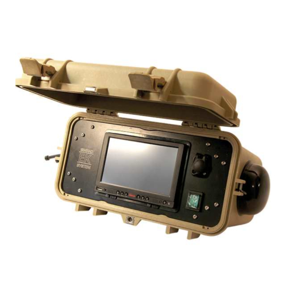
Page 107: Assembling A Portable Ek80 System
GPT Transducer plug connections, page 109 12-pin Amphenol plug , page 109 System diagram, portable The system diagram identifies the main components of a portable EK80 system. Only the main connections between the units are shown. The portable EK80 Wide band scientific echo sounder system consists of one transducer, one Wide Band Transceiver (WBT) and one computer. -
Page 108: Assembling A Portable System
Assembling a portable system does not require any special skills or tools. We will however suggest that initial unpacking and assembly take place in a workshop. The computer is not a standard part of the EK80 delivery. A suitable computer must be purchased locally. -
Page 109: Battery Power Cable (Wbt)
You can use this plug if you wish to operate the transceiver from a battery. The plug can be ordered from the manufacturer or purchased from Kongsberg Maritime. Use part number 390616. • : Switchcraft Conxall Manufacturer •... -
Page 110: Gpt Transducer Plug Connections
Used for specific transducer functionality Cable screen If you need more information about the transducer connections, refer to the documentation provided with the transducer, or to the EK80 Installation manual. Related topics Assembling a portable EK80 system, page 106 12-pin Amphenol plug The transducer socket on the transceiver allows you to connect one or more single or split beam transducers using a 12-pin Amphenol plug (97-24-19P). - Page 111 Kongsberg EK80 Reference Manual Disassemble the plug. Remove a few millimeters of the insulation on the individual cables. Fold the outer and inner screen backwards, and fasten them temporary with tape. Thread each wire through a heat-shrinkable tubing, solder the wire end...
-
Page 112: Operating Procedures
Operating procedures Operating procedures Topics Choosing operating mode and key transmit parameters, page 113 Controlling the gain and range settings, page 124 Defining the environmental settings, page 130 Recording and replaying raw echo data, page 135 Recording and exporting processed echo data, page 146 Saving and recalling screen captures, page 157 Capturing the display presentation in video files, page 161 Setting up the echogram presentation, page 163... - Page 113 Kongsberg EK80 Reference Manual Installing an ADCP transceiver in the user interface, page 330 Setting up the EK80 system for synchronized operation, page 343 Installing and maintaining software, page 357 Maintaining the EK80 system, page 369 Installing and troubleshooting Network Time Protocol (NTP), page 384...
-
Page 114: Choosing Operating Mode And Key Transmit Parameters
Opening the context-sensitive online help, page 123 Selecting Normal mode In order to transmit ("ping") you must set the EK80 system to Normal operating mode. Context function controls the operating mode of the EK80 system. You can set it to Operation Normal, Replay or Inactive. -
Page 115: Selecting Inactive Mode
In these cases the sounder may display the bottom at 0.0 metres at the top of the fish school. In order to aid the EK80 system to locate the correct depth, you must adjust to bottom maximum and minimum ranges according to the actual bottom depth. -
Page 116: Selecting Replay Mode
Choosing operating mode and key transmit parameters, page 113 Selecting Replay mode Replay mode allows you to play back previously recorded raw data. The EK80 system cannot operate normally while in Replay mode. Neither transmission nor reception takes place. Context All playback is controlled by the replay bar. -
Page 117: Selecting Advanced Sequencing Mode
Recording and replaying raw echo data, page 135 Operation function, page 549 Selecting Advanced Sequencing mode In order to use an advanced sequence you must set the EK80 to Advanced Sequencing operating mode. Prerequisites An advanced sequence has been created and saved previously. -
Page 118: Verifying That The Bottom Is Correctly Detected
Choosing operating mode and key transmit parameters, page 113 Verifying that the bottom is correctly detected Locating the bottom (seafloor) is important for the EK80 system. The EK80 system needs this bottom lock to locate the correct depth, and to stay on this depth during operation, even if the depth changes continuously. - Page 119 Result If the EK80 system should lose bottom detection due to air in the water or other disturbances, it will try to relocate the depth within the minimum and maximum depths you have defined.
-
Page 120: Defining The Ping (Transmission) Modes
Operating procedures Defining the ping (transmission) modes You can easily control how often the EK80 system shall transmit acoustic energy (a ping) into the water. You can disable the transmission altogether, set it to operate as fast as possible, or select a time interval. -
Page 121: Transmitting Single Pings
Choosing operating mode and key transmit parameters, page 113 Setting up the echogram presentation, page 163 Ping Mode function, page 561 Transmitting single pings You can set up the EK80 to transmit a single ping only when you select the button. Ping Context to control how often the EK80 system shall transmit its energy into the water. -
Page 122: Transmitting With Fixed-Time Intervals
Operating procedures Transmitting with fixed-time intervals You can set up the EK80 system to transmit pings with a fixed time interval. Context to control how often the EK80 system shall transmit its energy into the water. Ping Mode For normal use, choose Maximum. If you choose Maximum, the EK80 system will transmit (ping) continuously and as often as possible. -
Page 123: Switching Between Adcp And Echo Sounder Operation
(ADCP) instrument to measure water current or as a split-beam echo sounder. It can not operate these two functions simultaneously. Context This task is only applicable for a EK80 system fitted with relevant hardware for acoustic Doppler current profiler (ADCP) functionality. Procedure Open the menu. -
Page 124: Opening The Context-Sensitive Online Help
Operating procedures Opening the context-sensitive online help Installed on your EK80 system you will find a comprehensive context-sensitive online help system. Everything you can read in this publication can also be found in the online help. Help is also available from the various dialog boxes in the user interface. -
Page 125: Controlling The Gain And Range Settings
Adjusting the minimum level (echo sensitivity) On the EK80 you do not change the actual gain in the receiver, but the minimum level of the colour scale. When the numerical dB level is decreased, the weaker echoes will start to appear in the echogram. -
Page 126: Adjusting The Tvg (Time Variable Gain) Setting
Context The TVG (Time Variable Gain) compensation is designed to counteract the natural phenomena of geometric spread and absorption loss. In the EK80 system, the TVG compensation is made using digital signal processing software. You can select TVG using this function. You can also adjust the TVG setting in the Echogram dialog box. -
Page 127: Choosing Range And Start Range Values In A Surface-Related Echogram
The may be set to Auto, Range but for scientific purposes a fixed range is recommended. The Auto setting allows the EK80 to automatically determine the depth range based on bottom detection. 395234/J... - Page 128 Operating procedures Example in a surface-related echogram Start Range In a surface echogram, set the value to 0 metres. This will make Start Range the echogram start from the sea surface (provided that the transducer offset has been defined). Set to the current depth plus 20 metres.
-
Page 129: Choosing Range And Start Range Values In A Bottom-Related Echogram
Range value. Context setting defines how "deep" you wish the EK80 system to detect echoes. In other Range words, this is the vertical distance between the "top" and the "bottom" of the echogram. setting specifies the "bottom" depth, while the... - Page 130 Operating procedures Observe the menu. Main Its default location is on the right side of the display presentation. Locate the function. Start Range Choose a negative value for to place the start depth at the preferred distance Start Range over the sea bottom. The following methods can be used to adjust this setting: •...
-
Page 131: Defining The Environmental Settings
Specify the relevant environmental parameters. Specify the sound speed. If you select Calculated, the EK80 will calculate the sound speed based on the parameters you have provided. If you select Manual, you can provide your own value. To study the resulting absorption curve, observe the information at the bottom of the page. -
Page 132: Defining The Sound Speed Close To The Transducer
The sensor is often referred to as a sound velocity probe. If the sensor is not mounted, the sound speed information must be provided manually. The sensor is not a part of the EK80 system. This is a commercial item that can be purchased locally. -
Page 133: Loading A Sound Speed Profile
Setting up the input from a sound speed sensor If you have a sound speed sensor located close to the transducer face, you can import the information from this sensor. This will result in more accurate EK80 data. Prerequisites This procedure assumes that: •... - Page 134 Operating procedures • The EK80 system is turned on and operates normally. • The new sensor is physically connected to the EK80 system using a serial or network cable. The sensor is turned on and in normal operation. Neither tools nor instruments are required.
- Page 135 Kongsberg EK80 Reference Manual If you want to check that the peripheral system is transmitting data to the EK80 system, select Monitor dialog box provides one text box for incoming messages ( Port Monitor Rx Data and one for outgoing messages ( ).
-
Page 136: Recording And Replaying Raw Echo Data
Disabling the automatic echogram history recording, page 144 Defining the raw data recording parameters You can record raw and processed echo data on the EK80 system. The data are saved on the hard disk, or on an external data storage device, according to the preferences you have defined. - Page 137 • Select to use the same recording range for all your active channels. Common • Select to allow the EK80 system to automatically find the required range Auto value. • Select to use the different recording ranges for your active channels.
-
Page 138: Recording Raw Data
Record RAW Operation and then Replay mode. This mode allows you to play back previously recorded Operation data. In Replay mode the EK80 system is not able to transmit ("ping"). For this reason, the EK80 system is inactive during playback. 395234/J... - Page 139 This is only an Record Processed Operation export format. Processed data files can not be played back on the EK80 system. • For calibration purposes is recommended as the data format. This Complex Samples makes troubleshooting and quality assurance for calibration easier.
-
Page 140: Selecting Replay Mode
Operating procedures Selecting Replay mode Replay mode allows you to play back previously recorded raw data. The EK80 system cannot operate normally while in Replay mode. Neither transmission nor reception takes place. Context All playback is controlled by the replay bar. -
Page 141: Choosing Which Raw Data File(S) To Replay
When you record echo data the information is stored on the computer hard disk. Depending on your initial settings, the files can also be stored on an external storage device or a network disk. The echo data files can be retrieved and played back on the EK80 system. Context All playback is controlled by the replay bar. -
Page 142: Locating The Raw Data Files To Delete, Move Or Copy Them
Replay File dialog box, page 621 Locating the raw data files to delete, move or copy them Use the raw data recording functionality provided by the EK80 system to save echo data using the format. You can save the data to the hard disk, or onto an external storage *.raw... -
Page 143: Defining The Depth Range For Raw Data Recording
Recording and replaying raw echo data, page 135 Defining the depth range for raw data recording Before you start recording, you must specify the range you wish to use. The EK80 will only record the echo data retrieved between the selected setting and the total range. -
Page 144: Reducing The Raw Data File Sizes During Cw Recording
Select to allow the Range Auto EK80 system to automatically find the required range value. Select to use the different recording ranges for your active channels. Individual Limiting the recording range for high frequency channels is useful to reduce file size. -
Page 145: Disabling The Automatic Echogram History Recording
File Setup Select to use the default data format. Complex samples This is the data format that was first introduced with the EK80 system. The format stores the maximum amount of information, but requires a larger data storage capacity. Select to reduce the file sizes. - Page 146 Operating procedures Select Output Observe that the dialog box opens. This dialog box contains a number of pages Output selected from the menu on the left side. In the dialog box, select Output File Setup Under , deselect to disable the function. History History Logging Note...
-
Page 147: Recording And Exporting Processed Echo Data
Exporting sensor data to a peripheral system, page 155 Defining the processed data recording parameters The EK80 system allows you to record processed data. The data are saved on the hard disk, or on an external data storage device, according to the preferences you have defined. You can also define the which file format to use. - Page 148 Operating procedures Select Output Observe that the dialog box opens. This dialog box contains a number of pages Output selected from the menu on the left side. Select to open the page. File Setup Define the output directory for the recorded files. In order to change the output directory, both Record RAW Record Processed...
-
Page 149: Defining Recording Formats For Adcp Netcdf Outputs
Kongsberg EK80 Reference Manual Defining recording formats for ADCP netCDF outputs The EK80 system allows you to record processed data. The data are saved on the hard disk, or on an external data storage device, according to the preferences you have defined. You can also define the which file format to use. - Page 150 "top" and the "bottom" of the detection area. The EK80 system will only export data retrieved between the sea surface and the selected depth. The depth range is selected in metres.
-
Page 151: Recording Processed Data
Replay mode. This mode allows you to play back previously recorded Operation data. In Replay mode the EK80 system is not able to transmit ("ping"). For this reason, the EK80 system is inactive during playback. • A "history file" is recorded automatically and continuously. When the file is full it will start to overwrite the oldest data, thus creating a "ring buffer". - Page 152 Operating procedures Note The data files will normally become very large. If you wish to record large amounts of data, make sure that you have enough space on your hard disk. Unless your computer is equipped with a very large disk, we recommend that you save the data to an external storage device. You can record both RAW and processed data using the Record RAW Record Processed...
-
Page 153: Locating The Processed Data Files To Delete, Move Or Copy Them
You can also connect the Processing Unit to a network, and copy the files to a server. Context Processed data files can not be played back on the EK80 system. Procedure Prepare a data storage device. -
Page 154: Setting Up Depth Output To An External System
• The EK80 system is turned on and operates normally. Neither tools nor instruments are required. Context The EK80 system can export the information on several datagram formats. You can export several formats simultaneously, as each of them is handled independently. Procedure Connect the peripheral system to an available communication port on your computer. - Page 155 Kongsberg EK80 Reference Manual On the left side of the dialog box, select Output Depth Output Observe that the page opens. Depth Output Select to open the page. Processed Data to Output Select which depth datagram to export. Select the communication port you want to use.
-
Page 156: Exporting Sensor Data To A Peripheral System
The information provided to the EK80 system from various sensors can also be useful for other systems on board. The EK80 system allows you to export the same sensor data that was originally imported. This can "reuse" the same information on other systems. The Relay page is used to set up and control this export functionality. - Page 157 10 If you want to check the data flow on the selected port, select Monitor In order to see this data traffic, your EK80 system must be active and transmitting information to the peripheral system. dialog box provides one text box for incoming messages (...
-
Page 158: Saving And Recalling Screen Captures
Accessing the screen capture images to delete, move or copy them, page 159 Saving a screen capture While using the EK80 system you may wish to make a screen capture to save an instantaneous copy of the current presentation. Each screen capture you make is saved in format on the Processing Unit hard disk. -
Page 159: Recalling Single Echogram Screen Capture Images
Kongsberg EK80 Reference Manual Note The data files will normally become very large. If you wish to record large amounts of data, make sure that you have enough space on your hard disk. Unless your computer is equipped with a very large disk, we recommend that you save the data to an external storage device. -
Page 160: Accessing The Screen Capture Images To Delete, Move Or Copy Them
Operating procedures Procedure Observe the tab at the bottom of the display presentation. Screen Captures Select the tab to open the screen capture browser. Screen Captures Double-click the image you wish to enlarge. Select to close the image. Return to Browser To resume normal operation, select any other tab on the bottom bar. - Page 161 Kongsberg EK80 Reference Manual In the browser, select to open the operating system folder. Open Image Folder Use the functionality provided by the operating system to delete the files, or to copy or move them to the storage device. Close the file manager utility.
-
Page 162: Capturing The Display Presentation In Video Files
Operating procedures Capturing the display presentation in video files Topics Capturing the display presentation in a video file, page 161 Selecting where to save the video files, page 162 Capturing the display presentation in a video file function allows you to record and save the echo presentation as a Screen Recording video file. -
Page 163: Selecting Where To Save The Video Files
Kongsberg EK80 Reference Manual Select on the top bar one more time to stop the recording. Screen Recording Recording will automatically stop after 60 minutes. Selecting where to save the video files function allows you to record and save the echo presentation as a Screen Recording video file. -
Page 164: Setting Up The Echogram Presentation
Monitoring the survey operations from a client computer, page 183 Selecting which echogram type to use The EK80 system supports several different echogram types. Each echogram is shown in a separate view in the display presentation. To select which echogram types you wish to see in the display presentations, use the dialog box. - Page 165 Kongsberg EK80 Reference Manual • Surface: A Surface echogram is mainly used when you wish to look at the entire water column starting from the sea surface and down to the sea bottom. • Bottom: A Bottom echogram is mainly used when you want to examine the echoes from fish close to the sea bottom.
-
Page 166: Selecting Echogram Views On The Bottom Bar
The number of tabs available on the bottom bar depends on how many channels your system has. Two tab "groups" allow you to select channels and views. This example shows a EK80 system with two channels. In this context, the term channel is used as a common term to identify the combination of transceiver, transducer and operating frequency. -
Page 167: Changing The Size Of The Echogram Views
Lines and markers, page 494 Changing the size of the echogram views You can modify the size of each individual echogram view in the EK80 presentation. Context The physical size of each echogram or other view can be changed individually. The content in a view that changes size will automatically be adjusted to take full advantage of the space available. -
Page 168: Defining The Ping (Transmission) Modes
Lines and markers, page 494 Defining the ping (transmission) modes You can easily control how often the EK80 system shall transmit acoustic energy (a ping) into the water. You can disable the transmission altogether, set it to operate as fast as possible, or select a time interval. -
Page 169: Choosing The Colours Used To Present The Echograms
Select either side of the button to choose a value. Select the middle of the button to open it. If you have a keyboard connected to the EK80 system, type the requested value. You can also change the value by selecting - and holding - the middle of the button, and move the cursor sideways. - Page 170 Operating procedures By default you have 64 or 12 colours available to present the echoes, and a selection of palettes. The colour scale can be retrieved any time by selecting on the top bar. Colour Scale The chosen colours are shown on the bottom bar at the bottom of the display presentation. If you choose to use many colours, the resolution of the display presentation is greatly improved.
-
Page 171: Adjusting The Tvg In The Echogram Dialog Box
That is why we normally refer to these factors as the two-way transmission loss. The TVG (Time Variable Gain) compensation is designed to counteract the natural phenomena of geometric spread and absorption loss. In the EK80 system, the TVG compensation is made using digital signal processing software. -
Page 172: Selecting The Horizontal Scale In The Echograms
Operating procedures Procedure Click in the echogram view you want to change. The active view is identified with a thicker border. Open the menu. Active Select Echogram Observe that the dialog box opens. Echogram In the dialog box, select the tab to open the page. - Page 173 Kongsberg EK80 Reference Manual • : The horizontal scale is based on the number of transmissions (“pings”) made. Ping Select to specify that the number of horizontal pixels shall define the number View Size of displayed horizontal pings using one ping per pixel.
-
Page 174: Adding Scale Labels To The Echograms
The distance shown in the bottom right corner of the echogram is then 0 nautical miles (starting point). This is a visual enhancement. The choice you make has no effect on the overall performance of the EK80 system. Procedure Click once in the view that you wish to change. -
Page 175: Adding Horizontal Depth Lines To The Echograms
Kongsberg EK80 Reference Manual Related topics Setting up the echogram presentation, page 163 Echogram views, page 465 Lines and markers, page 494 Horizontal Axis page, page 826 Adding horizontal depth lines to the echograms When enabled, equidistant horizontal scale lines are drawn inside the view in the current foreground colour;... -
Page 176: Monitoring The Biomass In The Echogram
The biomass line shows you the integrated biomass for the pings within the selected calculation interval.This is a visual enhancement. The choice you make has no effect on the overall performance of the EK80 system. You can also measure the biomass in the Biomass information pane. The Biomass information pane displays an index of the biomass in the current view. -
Page 177: Enhancing The Bottom Contour In The Echograms
Kongsberg EK80 Reference Manual Close the dialog box. Related topics Setting up the echogram presentation, page 163 Echogram views, page 465 Lines and markers, page 494 Lines page, page 819 Biomass information pane description, page 441 Enhancing the bottom contour in the echograms Certain visual enhancements may be applied to make it easier to identify the bottom. -
Page 178: Adding Vertical Marker Lines To The Echogram
Note This is a visual enhancement. The choice you make has no effect on the overall performance of the EK80 system. Procedure Click once in the relevant view. The view is activated. It is identified with a thick border. -
Page 179: Adding Automatic Trawl Lines To The Echogram Presentation
Trawl sensor systems (such as Kongsberg PI, PX and ITI) communicate headrope depth, and/or the distance from the headrope to the footrope (trawl opening), to the EK80 system at regular intervals. The information can be used to draw the upper and/or lower trawl lines in the echogram. -
Page 180: Adding Manual Trawl Lines To The Echogram Presentation
Lines page, page 819 Adding manual trawl lines to the echogram presentation When you use a trawl, the EK80 can draw the upper and lower trawl lines in the echogram. Context A Simrad ITI (Integrated Trawl Instrumentation) system can be connected to the EK80 system. -
Page 181: Adding Comments And Annotations To The Echograms
Kongsberg EK80 Reference Manual If another trawl or catch monitoring system is used, and this system does not provide the trawl opening and/or trawl distance automatically, the values must be entered manually. Procedure Open the menu. Setup On the menu, select... - Page 182 Operating procedures or simply for keeping track of time or distance. The page is located in the Annotations dialog box. Installation page in the dialog box allows you to enable or disable annotations in Lines Echogram the echograms. Annotations can only be added to views while in Normal operational mode. When you save raw data, the annotations you have defined are stored as annotation datagrams.
-
Page 183: Adding A Single Text Comment To The Echogram
Type any text into the box. The size of the box will adjust to the length of your text. If you do not have a computer keyboard connected to your EK80 system, select the button to open an on-screen keyboard. -
Page 184: Monitoring The Survey Operations From A Client Computer
The communication between the EK80 Client application and the EK80 can be made using the vessel’s local area network. In this context the EK80 Processing Unit is regarded as the "server". The computer that runs the EK80 client application is the "client". - Page 185 Kongsberg EK80 Reference Manual Related topics Setting up the echogram presentation, page 163 Echogram views, page 465 Lines and markers, page 494 Client Server Configuration page, page 725 395234/J...
-
Page 186: Using The Information Panes To Collect Data From The Echoes
Context The information panes provided by the EK80 system can be placed anywhere on top of the views in the presentation. In order not to loose information, the panes have been designed so you can see through them. -
Page 187: Retrieving The Latest Echogram History
Select the right side of the button to increase the value. Select the middle of the button to open it. If you have a keyboard connected to the EK80 system, type the requested value. Related topics Defining settings related to user preferences and individual customizing, page 262... -
Page 188: Disabling The Automatic Echogram History Recording
Operating procedures Procedure Click in the view you want to activate. The data in the information pane is only valid for the selected channel. The active view is identified with a thicker border. On the top bar, select History In order to show you the recorded echograms, the echogram presentation is split in two. -
Page 189: Changing The Colour Scale In The Echo Presentations
The colour scales are designed to reflect how strong the echoes are. The echo strength is measured in decibels (dB). In the basic colour scale with 12 colours, each colour represents a 3 dB step. This means that the entire scale covers 36 dB. The dynamic range of the EK80 system is much larger. The... - Page 190 The chosen transparency percentage is used on all open information panes. Investigate the information provided by the information pane. The EK80 system has a dynamic range of 140 dB. This means that the EK80 system can receive both very strong and very weak echoes. Naturally, we can not present all these echoes on the display simultaneously, as this would create a mess of colours.
-
Page 191: Opening The Depth Information Pane To Read The Current Depth
Kongsberg EK80 Reference Manual Opening the Depth information pane to read the current depth You can easily read the current water depth in the Depth information pane. Context The Depth information pane provides the water depth in the current echogram view. If you have several echogram views open, you can place one pane in each view. -
Page 192: Investigating The Bottom Characteristics
Operating procedures Selecting in the Depth information pane opens the page in the Setup Bottom Detection dialog box. The purpose of the settings is to Information Pane Options Bottom Detection define the upper and lower depth limits most likely to be used during normal operation. Select in the top right corner to close the information pane. -
Page 193: Changing The Calculation Parameters For The Ts Histogram Information Pane
Setup Select to open the dialog box. Calculation Interval Adjust the setting to fit your requirements. • Select to allow the EK80 export to make the calculations based on the echo Distance data collected during a sailed distance. 395234/J... -
Page 194: Investigating The Biomass
It is possible to convert the biomass index to weight (for example in metric tons). Based on practical use of the EK80 system in different fisheries, you will soon be able to estimate the weight when you know the type of fish and their sizes. -
Page 195: Changing The Calculation Parameters For The Biomass Information Pane
The chosen transparency percentage is used on all open information panes. Investigate the information provided by the information pane. The EK80 system records all the targets from the smallest plankton to the largest whale. The biomass value is an indicator to how much fish you currently have in the beam. -
Page 196: Creating A Sv(F) Information Pane With Echo Data From Multiple Channels
Combined View Settings Prerequisites The dialog box can only be opened if you have more than one channel in your EK80 presentation. In this context, the term channel is used as a common term to identify the combination of transceiver, transducer and operating frequency. - Page 197 Kongsberg EK80 Reference Manual Context Combined View Settings dialog box lists all your current channels. When activated, a dedicated view is created to hold the information pane and one echogram. Procedure Open the menu. Active Select Combined View to open the Settings dialog box.
-
Page 198: Monitoring The Numerical Information In A Depth Layer
Operating procedures Monitoring the numerical information in a depth layer The Numerical information pane is the best tool for controlling your depth layers. All layers are listed, even those that may be located outside your current echogram presentation. The different layers can easily be activated by clicking the list of numerical data. Context Once you create your own layer, all calculated values... - Page 199 Kongsberg EK80 Reference Manual Note The layers are a key function of the EK80. During normal operation, make sure that you are aware of the layer(s) that you have established, and that the requested layer is activated to feed information to the information panes.
-
Page 200: Using The Zoom Information Pane To Study Details In The Echogram
Operating procedures Using the Zoom information pane to study details in the echogram If you need to magnify a part of the echogram to study details, you can use the Zoom information pane. Context The Zoom information pane allows you to magnify a chosen area of the current echogram. Once the Zoom information pane is opened, the zoomed area is shown as a dotted rectangle in the view. -
Page 201: Monitoring The Supply Voltage
This is very useful if you operate your EK80 from a battery. Context If you operate your EK80 from a battery, it is very useful to keep an eye on the supply voltage. The EK80 software measures this supply voltage in the transceiver, and the result is automatically returned to the Transceiver Power Supply information pane. - Page 202 10%. The function is located on the menu. Transparency Display Select in the top right corner to close the information pane. Close Related topics Maintaining the EK80 system, page 369 Transceiver Power Supply information pane description, page 457 395234/J...
-
Page 203: Working With Depth Layers In The Echogram Views
In order to study these species, the EK80 supports a Layer function. By means of this function, you can create your own depth layers in the water column to improve the dynamic data required for analysis. - Page 204 Operating procedures Procedure Open the menu. Active Select New Layer Observe that the dialog box opens. New Layer Select layer type. • : The range settings for the layer are referenced to the surface. The layer Surface is downwards limited by the detected bottom depth if this value is shallower than 395234/J...
- Page 205 Kongsberg EK80 Reference Manual the specified lower range limit for the layer. "Pings" without a bottom detection are ignored in the calculations. • : The range settings for the layer are referenced to the surface. The layer is Pelagic not downwards limited by the detected bottom depth.
-
Page 206: Modifying The Properties Of An Existing Depth Layer
Operating procedures Modifying the properties of an existing depth layer You can create as many depth layers as you want on the EK80. Once a depth layer has been made you can change its properties using the dialog box. Layer Properties Context When a layer is established, it is drawn with two horizontal lines in the echograms. -
Page 207: Deleting A Depth Layer
Deleting a depth layer You can create as many depth layers as you want on the EK80. The active layer is shown with red border lines. A single layer can be deleted if you do not need it any longer. - Page 208 Operating procedures The Numerical information pane is the best tool for controlling your depth layers. All layers are listed, even those that may be located outside your current echogram presentation. The different layers can easily be activated by clicking the list of numerical data. Procedure Select an "active"...
-
Page 209: Monitoring The Numerical Information In A Depth Layer
Kongsberg EK80 Reference Manual Monitoring the numerical information in a depth layer The Numerical information pane is the best tool for controlling your depth layers. All layers are listed, even those that may be located outside your current echogram presentation. The different layers can easily be activated by clicking the list of numerical data. - Page 210 Operating procedures Note The layers are a key function of the EK80. During normal operation, make sure that you are aware of the layer(s) that you have established, and that the requested layer is activated to feed information to the information panes.
-
Page 211: Exploring Water Velocities Using Adcp
Kongsberg EK80 Reference Manual Exploring water velocities using ADCP These tasks are only applicable for a EK80 system fitted with relevant hardware for acoustic Doppler current profiler (ADCP) functionality. Note The EC150-3C is a dual purpose unit. It can be used either as an acoustic Doppler current profiler (ADCP) instrument to measure water current or as a split-beam echo sounder. - Page 212 Operating procedures The vertical velocity presentation is optional. The presentation can be enabled or disabled on the page. The page is located in the dialog box. ADCP ADCP Information Pane Options Each measurement of the water current velocity is presented as a vector drawn as an arrow. The length of the arrow indicates the velocity of the water.
-
Page 213: Identifying The Vessel Heading In The Adcp Information Pane
Kongsberg EK80 Reference Manual Click the bottom right corner of the information pane, and drag to requested size. To close the information pane, select it one more time on the top bar. You can also select in the top right corner of the pane. -
Page 214: Selecting Compass Orientation For Horizontal Water Velocities
Prerequisites This information pane is available only when ADCP functionality is activated. Context This is a visual enhancement. The choice you make has no effect on the overall performance of the EK80 system. Procedure Open the page. ADCP Open the menu. -
Page 215: Controlling The Scale In The Compass Rose Presentation
Kongsberg EK80 Reference Manual Open the page. ADCP Choose the required setting. • Select to place the vessel with its bow up at all times. The presentation of Bow Up the velocities, regardless of any relativity, will adapt to this setting. -
Page 216: Setting The Velocity Vectors To True Or Relative Bearing
Open the page. ADCP Select an appropriate value for the Maximum Speed Select if you want the EK80 system to provide automatic scaling. Auto Velocity can be measured in different units. Choose the unit of measurement on the page. Units Select to save your choice. - Page 217 Kongsberg EK80 Reference Manual Context This is a visual enhancement. The choice you make has no effect on the overall performance of the EK80 system. Procedure Open the page. ADCP Open the menu. Active Select Information Pane Options You can also open the...
-
Page 218: Setting The Compass Rose Presentation To True Or Relative Bearing
The "compass rose" presentation will be applied with either cardinal or vessel relative directions. Note This is a visual enhancement. The choice you make has no effect on the overall performance of the EK80 system. Procedure Open the page. ADCP Open the menu. -
Page 219: Providing Vertical Velocity In The Adcp Information Pane
Kongsberg EK80 Reference Manual You can also open the dialog box by selecting Information Pane Options Setup in selected information panes. Open the page. ADCP Choose the appropriate settings for Compass • Select to set up the presentation relative to the cardinal directions Geographical (north. -
Page 220: Changing The Speed Range Display For Vertical Current Velocity
Operating procedures Note This is a visual enhancement. The choice you make has no effect on the overall performance of the EK80 system. Procedure Open the menu. Active Select Information Pane Options You can also open the dialog box by selecting... - Page 221 Kongsberg EK80 Reference Manual Note This is a visual enhancement. The choice you make has no effect on the overall performance of the EK80 system. Procedure Open the menu. Active Select Information Pane Options You can also open the dialog box by selecting...
-
Page 222: Adjusting The Adcp Quality Parameters
Operating procedures Adjusting the ADCP quality parameters These tasks are only applicable for a EK80 system fitted with relevant hardware for acoustic Doppler current profiler (ADCP) functionality. Note The EC150-3C is a dual purpose unit. It can be used either as an acoustic Doppler current profiler (ADCP) instrument to measure water current or as a split-beam echo sounder. - Page 223 Kongsberg EK80 Reference Manual If the correlation for any of the beams is smaller than the selected threshold value, that measurement is removed from the data. The correlation decreases with distance from the transducer. Of you set the Correlation threshold to 0 (zero) you will disable the filter.
-
Page 224: Improving Adcp Data Quality Using An Error Velocity Threshold Limit
Error Velocity relation to the scientific survey and the water conditions in the area. Note This is a visual enhancement. The choice you make has no effect on the overall performance of the EK80 system. Procedure Open the menu. Active... -
Page 225: Improving Adcp Data Quality With A Correlation Threshold Value
Kongsberg EK80 Reference Manual Improving ADCP data quality with a correlation threshold value Correlation is a measure of quality for velocities measured in the ADCP beams. High correlation indicates a low level of noise for the signals and a high quality for the velocity estimates. -
Page 226: Improving Adcp Data Quality With A Percent Good Threshold Value
Averaged velocities, ADCP data, with percent good below this limit are not shown in the velocity views. Note This is a visual enhancement. The choice you make has no effect on the overall performance of the EK80 system. Procedure Open the menu. - Page 227 Kongsberg EK80 Reference Manual Related topics Adjusting the ADCP quality parameters, page 221 Acoustic Doppler current profiler, page 855 ADCP Editing dialog box, page 617 395234/J...
-
Page 228: Setting Up The Adcp Presentation
Operating procedures Setting up the ADCP presentation These tasks are only applicable for a EK80 system fitted with relevant hardware for acoustic Doppler current profiler (ADCP) functionality. Note The EC150-3C is a dual purpose unit. It can be used either as an acoustic Doppler current profiler (ADCP) instrument to measure water current or as a split-beam echo sounder. - Page 229 Kongsberg EK80 Reference Manual Vessel Velocity The Vessel Velocity views display water velocities relative to the vessel. The views display water velocity in fore/aft and port/starboard direction as well as down towards the seafloor. Vessel speed is displayed separately. Geo Velocity The Geo Velocity views display water velocity relative to earth coordinates, i.e.
-
Page 230: Selecting Velocity Measurement (Adcp) Views Using The Bottom Bar
Operating procedures Check the box for each view you would like to present. Select view orientation. Select to examine data over a certain period of time or distance. Horizontal Horizontal orientation mode arranges the views adjacent to each other horizontally. This is a useful presentation mode if you want to see ADCP data over a longer period of time or distance. -
Page 231: Changing The Size Of The Individual Velocity Measurement (Adcp) Views
The views are organized in presentation modes. Which presentation mode to use is selected with the tabs at the bottom of the EK80 presentation. The phrase presentation mode is used to describe the combination of views that are shown when the mode is selected at the bottom of the display presentation. -
Page 232: Placing Velocity Measurement (Adcp) Views In A Separate Window
Operating procedures function provided by the EK80 system allows you to rearrange the Docking Views physical positions of the views, and to change their sizes. Once the function is Docking Views activated, the various views are placed in named windows, and docking positions for these windows are shown. - Page 233 Kongsberg EK80 Reference Manual Context Using more than one window to present information is useful for a number of reasons. Separate windows on several display monitors (or on a single large display) provide a great overview when you want to display a lot of information. If you want to present the same information with different settings, use two (or more) windows to provide the views.
-
Page 234: Adjusting The Colours In The Velocity Measurement (Adcp) Views
Adjusting the colours in the velocity measurement (ADCP) views The velocity measurement (ADCP) views provided by the EK80 system present the data using colours. This information is shown using either a bipolar representation or a gradient single colour representation. The colour and/or the saturation of a colour indicates the magnitude of the ADCP data. -
Page 235: Reducing The Random Errors In Adcp Measurements
Kongsberg EK80 Reference Manual Related topics Setting up the ADCP presentation, page 227 ADCP Colour Span function, page 591 Reducing the random errors in ADCP measurements There will always be random noise in water velocity estimates. The random noise can be reduced by using the averaging the velocity estimates over a fixed number of pings. -
Page 236: Selecting The Horizontal Scale In The Adcp Views
Operating procedures Selecting the horizontal scale in the ADCP views The horizontal scale controls how fast the ADCP data move from right towards left across the EK80 presentation You can change the horizontal scale on the page in Horizontal Axis dialog box. -
Page 237: Adding Scale Labels To The Adcp Views
0 nautical miles (starting point). This is a visual enhancement. The choice you make has no effect on the overall performance of the EK80 system. Procedure Click once in the view that you wish to change. -
Page 238: Enhancing The Bottom Contour In Adcp Views
You can use the white and the bottom lines simultaneously. Select to disable the line. Normal You can use the white and the bottom lines simultaneously. Note This is a visual enhancement. The choice you make has no effect on the overall performance of the EK80 system. 395234/J... -
Page 239: Setting The Drawing Range For The Adcp Views
Kongsberg EK80 Reference Manual Procedure Click once in the view that you wish to change. The view is activated. It is identified with a thick border. Open the menu. Active Select to open the dialog box. ADCP View Settings On the left side of the dialog box, select to open the page. - Page 240 Operating procedures hit the sea floor can be significant. Water velocity calculations are performed according to the range specified. • : Drawing range is specified by the number of samples available. The drawing range Full in the ADCP views will be the range of the ADCP transducer. This is limited by view range and recording range set in the user interface.
-
Page 241: Adding Vertical Marker Lines To The Adcp Views
Kongsberg EK80 Reference Manual Adding vertical marker lines to the ADCP views You can add short vertical marker lines to you ADCP presentation. These lines are used to measure time or distance. Context The following options are available: • : No vertical markers are shown. -
Page 242: Adding Comments And Annotations To Adcp Views
Operating procedures Adding comments and annotations to ADCP views When you study ADCP data it can often be useful to add personal comments to it to identify specific occurrences at specific time intervals or distances. Several different annotation types may be added. The annotations are shown on the ADCP view if this feature has been enabled in the dialog box. -
Page 243: Adding A Single Text Comment To An Adcp View
Type any text into the box. The size of the box will adjust to the length of your text. If you do not have a computer keyboard connected to your EK80 system, select the button to open an on-screen keyboard. -
Page 244: Working With Advanced Sequences
• You are familiar with the objective of the survey and how the echo sounder works. • The EK80 is running in Normal or Inactive operating mode. • All transducers used in an advanced sequence must be installed in the EK80. Context Advanced sequencing opens a world of possibilities. - Page 245 Note When you provide a name, you can save your setup. It is not possible to copy and share defined sequences between different EK80 systems. EK80 parameter values included in the sequence definitions are specific for each EK80 installation. Select the ensembles to include in the advanced sequence.
-
Page 246: Editing An Advanced Sequence
• An advanced sequence has been created and saved. • The EK80 is running in Normal or Inactive operating mode. • All transducers used in an advanced sequence must be installed in the EK80. Context An advanced sequence in the EK80is defined by ping, ping groups, ensembles and sequences which are repeated a fixed number of times. -
Page 247: Creating An Advanced Sequence - Example
• You are familiar with the objective of the survey and how the echo sounder works. • The EK80 is running in Normal or Inactive operating mode. • All transducers used in an advanced sequence must be installed in the EK80. Context This is an example where you create an advanced sequence consisting of ping configurations, ping groups and ensembles. - Page 248 Operating procedures Procedure Select Advanced Sequencing is located in the menu. Advanced Sequencing Setup Create two ping configurations, one for passive mode and one for active mode. Select in the page. Ping Type a name for the ping configuration. Enter the parameters for the ping configuration. Select to save the ping configuration.
-
Page 249: Uploading And Activating An Advanced Sequence
Context Caution You must never set the EK80 system to ping unless the transducer is submerged in water. Most transducers are damaged beyond repair if they transmit in open air. Prevent inadvertent use of the EK80 system whenever a transducer is not submerged. -
Page 250: Deactivating An Advanced Sequence
Operating procedures function enables or disables the transmissions into the water. Ping Ping Mode parameters are defined in the advanced sequence. Ping Interval Result Your advanced sequence has been activated. Related topics Working with advanced sequences, page 243 Pages in the Advanced Sequencing dialog box, page 670 Select Sequence function, page 559 Deactivating an advanced sequence The advanced sequence can be deactivated at any time. -
Page 251: Working With Pings, Ping Groups And Ensembles
Prerequisites • The EK80 is running in Normal or Inactive operating mode. • All transducers used in an advanced sequence must be installed in the EK80. Context A ping defines the properties of a transmission (ping) from a specific transducer. You can define multiple numbers of pings and combine these into ping groups for the specific transducer. -
Page 252: Creating A Ping Group
• One or more ping must have been saved previously. • The EK80 is running in Normal or Inactive operating mode. • All transducers used in an advanced sequence must be installed in the EK80. Context A ping group defines the properties of each transmission (ping) for each transducer. You can define multiple ping groups for each advanced sequence Each ping group is defined with a name that you choose. - Page 253 The EK80 system transmits (pings) with a fixed time interval. Ping Interval permits you to choose the time (in milliseconds) between each transmission (ping). If you choose Maximum, the EK80 system will transmit (ping) continuously and as often as possible. Select a ping to include in the ping group.
-
Page 254: Creating Ensembles
• One or more ping groups must have been saved previously. • The EK80 is running in Normal or Inactive operating mode. • All transducers used in an advanced sequence must be installed in the EK80. Context An ensemble is a collection of one or more ping groups. The intention of an ensemble is to perform repeating sets of different configurations. - Page 255 Kongsberg EK80 Reference Manual Click on the button next to Include Available Ping Groups The selected ping group will appear in the . Details Current Ensemble Ping Groups of the ping group and pings will appear at the bottom of the field.Click...
-
Page 256: Setting Up Presentation Modes And Views
Restoring the locations and sizes of the views, page 258 Rearranging the tabs at the bottom of the EK80 presentation, page 259 Creating personalized views by adding a new tab to the bottom of the EK80 presentation, page 260 Removing personalized presentations, page 261... -
Page 257: Rearranging The Layout Of The Echo Presentations
The information from each channel is shown in a separate view. The function Docking Views provided by the EK80 system allows you to rearrange the physical positions of the views, and to change their sizes. Context The physical location and size of each view can be changed individually. The content in a view that changes size will automatically be adjusted to take full advantage of the space available. -
Page 258: Moving A View To Another Display
The frame of the selected view will change colour to indicate that it has been selected. Press the mouse button, and keep it depressed to drag the selected view to another position in the EK80 presentation. The docking positions show you where to drag and drop the selected view. Any view can be selected, and then repositioned as indicated by the docking positions. -
Page 259: Restoring The Locations And Sizes Of The Views
User Settings Context function provided by the EK80 system allows you to rearrange the Docking Views physical positions of the views, and to change their sizes. When a complete reorganisation of the view positions and sizes have been completed, you may wish to restore the presentation to what it was before you changed it. -
Page 260: Rearranging The Tabs At The Bottom Of The Ek80 Presentation
Each of these appears as a tab on the bottom bar. Select a mode in the list. Select any of the two arrows to position the tab at the bottom of the EK80 presentation. Select to save the selected setting and close the dialog box. -
Page 261: Creating Personalized Views By Adding A New Tab To The Bottom Of The Ek80 Presentation
Presentation Modes Type a name for the new mode. Select Select any of the two arrows to position the tab at the bottom of the EK80 presentation. Select to save the selected setting and close the dialog box. -
Page 262: Removing Personalized Presentations
Context The views are organized in presentation modes. Which presentation mode to use is selected with the tabs at the bottom of the EK80 presentation. The phrase presentation mode is used to describe the combination of views that are shown when the mode is selected at the bottom of the display presentation. -
Page 263: Defining Settings Related To User Preferences And Individual Customizing
Kongsberg EK80 Reference Manual Defining settings related to user preferences and individual customizing Topics Reducing the light emitted from the display presentation, page 262 Increasing the visibility of the information panes, page 263 Enabling Coordinated Universal Time (UTC) on the bottom bar, page 264... -
Page 264: Increasing The Visibility Of The Information Panes
Context The information panes provided by the EK80 system can be placed anywhere on top of the views in the presentation. In order not to loose information, the panes have been designed so you can see through them. -
Page 265: Enabling Coordinated Universal Time (Utc) On The Bottom Bar
EK80 system uses local time. Prerequisites To enable UTC time, your EK80 system must be set up to accept the NMEA ZDA datagram. The NMEA ZDA datagram contains the universal time code (UTC), day, month, year and local time zone. -
Page 266: Selecting The Information To Appear On The Top Bar
Operating procedures Related topics Defining settings related to user preferences and individual customizing, page 262 Display Options dialog box, page 572 General page, page 660 Bottom bar description, page 505 Selecting the information to appear on the top bar The top bar can contain various information. You can choose which information elements to appear at the top of the display presentation. -
Page 267: Selecting Which Tooltips To Appear In The User Interface
Changing the colour palette ("skin") used in the display presentations Depending on the ambient light, it is possible to change the colours the EK80 system uses in its display presentation. This can help you see the information better. The function Palette allows you to choose which colour theme ("skin") to be used by the EK80 system. -
Page 268: Selecting Menu Language
Colour Setup dialog box, page 572 Selecting menu language You may prefer to use the EK80 system with the user interface in your own language. The function allows you to select the language to be used in the display presentations, Language menus and dialog boxes. -
Page 269: Selecting Measurement Units
Defining settings related to user preferences and individual customizing, page 262 Language function, page 586 Selecting measurement units The EK80 system is prepared to work with several international standards for units of measurements. From the page you control which units of measurements are used. -
Page 270: Saving, Retrieving And Handling User Settings
Choosing factory default settings, page 273 Saving the current user settings When you have spent some time working with the EK80 system, you are probably using specific settings that you know are efficient for your purpose. It is a good idea to save these settings. -
Page 271: Choosing Previously Saved User Settings
Choosing previously saved user settings User settings that either you or any of your colleagues have saved can easily be retrieved and put to use. This shortens down the time it takes to get started with the EK80 system. Context dialog box is used to store your favourite settings. -
Page 272: Renaming Existing User Settings
Select Rename A small dialog box opens to accept the new name. Type a name. If you do not have a computer keyboard connected to your EK80 system, select the button to open an on-screen keyboard. Keyboard Select to save the chosen name. -
Page 273: Deleting User Settings That Are No Longer Used
Kongsberg EK80 Reference Manual Related topics Saving, retrieving and handling user settings, page 269 Operating procedures, page 111 User Settings dialog box, page 540 Deleting user settings that are no longer used When you save the user settings, the files you have created are shown on the Saved Settings list. -
Page 274: Choosing Factory Default Settings
Operating procedures Choosing factory default settings Sometimes it may be useful to reset the EK80 system to work with a set of known user settings. A set of "factory settings" is provided for this purpose. The factory settings may be put to use if you are uncertain of which values to use. They offer the "best practice"... -
Page 275: Adjusting The Transceiver Parameters
You can change the parameters. Prerequisites This procedure assumes that the EK80 system is turned on and operates normally. The dialog box is only available when the EK80 system operates in Normal Normal Operation mode. -
Page 276: Selecting Passive Transceiver Mode
This mode is useful for test purposes, and when you want to measure the ambient background noise in the sea. It can be useful to run the EK80 system in Passive mode to discriminate between target echoes (present only in Active mode) and noise (present in both Active and Passive modes). -
Page 277: Adjusting The Output Power
Transceiver page, page 791 Adjusting the output power You are permitted to adjust the output power of the EK80 system. You can not increase the power to beyond the transducer’s capacity, but you may reduce it for better performance in shallow water, or if you are struggling with reverberation. -
Page 278: Adjusting The Pulse Duration
The pulse duration can be selected according to the current depth and what kind of fish you are looking for. The deeper you wish to see, the longer pulse duration should be selected. Remember that in the EK80 system, the pulse duration and the bandwidth are mutually dependant. -
Page 279: Defining The Frequency Sweep (Chirp) Within Each Transmission
Transceiver page, page 791 Defining the frequency sweep (chirp) within each transmission The EK80 system supports wideband transmissions using frequency sweeps. This is often referred to as "chirp", and means that the transmission frequency changes from a "start" frequency to an "end" frequency within the transmission. In order to use the frequency sweep ("chirp") functionality, you must use frequency modulated pulses. -
Page 280: Defining The Pulse Type For The Ek80 Transmissions
Extras menu, page 534 Normal Operation dialog box, page 552 Processor page, page 787 Transceiver page, page 791 Defining the pulse type for the EK80 transmissions function allows you to select the "shape" of the transmitted pulses ("pings"). Pulse Type Context The abbreviation "CW"... -
Page 281: Increasing The Detection Of Small Targets Masked By Stronger Echoes
Pulse Duration Remember that in the EK80 system, the pulse duration and the bandwidth are mutually dependant. For CW (Continuous Wave) transmissions: • Long pulses provides longer detection range. They make the EK80 system less sensitive for noise, but offer lower range resolution. -
Page 282: Switching Between Adcp And Echo Sounder Operation
(ADCP) instrument to measure water current or as a split-beam echo sounder. It can not operate these two functions simultaneously. Context This task is only applicable for a EK80 system fitted with relevant hardware for acoustic Doppler current profiler (ADCP) functionality. Procedure Open the menu. -
Page 283: Adjusting The Specific Transceiver Parameters For Adcp Operation
Note This task is only applicable for a EK80 system fitted with relevant hardware for acoustic Doppler current profiler (ADCP) functionality. Procedure Open the menu. -
Page 284: Measuring The Noise In Passive Mode
Transceiver page, page 791 Measuring the noise in passive mode You can create as many depth layers as you want on the EK80. Each of the depth layers can be used to measure the background (ambient) noise in the water column. - Page 285 Kongsberg EK80 Reference Manual Open the menu. Operation Select Normal Operation For the relevant transceiver channel, set to Passive. Mode Select to save the selected setting and close the dialog box. Create a new layer Open the menu. Active Select New Layer to Pelagic.
-
Page 286: Interfacing Peripheral Equipment
Sensor Installation Sensor Configuration priority, so that the information from the "most reliable" sensor is used by the EK80 system. You can also define manual values in case a sensor is unserviceable, or not installed. Prerequisites The new sensor is physically connected to the EK80 system using a serial or network cable. - Page 287 Kongsberg EK80 Reference Manual relevant communication parameters. Once the communication has been established and the sensor is connected, you must define the datagram priority and finalize the configuration. Note Just making changes and selecting at the bottom of the page will not install anything.
-
Page 288: Defining The Serial And Ethernet (Lan) Port Parameters
For any sensor interface to work, the communication parameters must be set up correctly. The EK80 software automatically scans the Processing Unit to locate and identify the available communication ports. Once the software has established a list of valid interfaces, you can set up and control the communication parameters. -
Page 289: Setting Up The Input From A Navigation System (Gps)
Network) or serial port). You can type a custom name to identify the sensor import. In the list of valid datagram formats, select the format(s) to be accepted by the EK80 system. For each relevant sensor you must insert the offset values that define the its physical location relative to the vessel’s coordinate system. - Page 290 You cannot make any changes here. To change the communication parameters, use page. I/O Setup If you want to check that the peripheral system is transmitting data to the EK80 system, select Monitor dialog box provides one text box for incoming messages (...
- Page 291 These offset values are all required to allow the EK80 system to give you as accurate information as possible. The degree of accuracy offered by the EK80 system is directly related to the accuracy of the information you enter on the page.
-
Page 292: Configuring The Sensor Priority
Sensor Configuration from the "most reliable" sensor is used by the EK80 system. You can also define manual values in case a sensor is unserviceable, or not installed. - Page 293 Kongsberg EK80 Reference Manual Procedure Open the menu. Setup On the menu, select Setup Installation Observe that the dialog box opens. This dialog box contains a number of Installation pages selected from the menu on the left side. On the left side of the...
-
Page 294: Setting Up A Serial Or Lan (Ethernet) Port For Annotation Input
You must specify which communication port to use (LAN (Local Area Network) or serial port). You can type a custom name to identify the sensor import. In the list of valid datagram formats, select the format(s) to be accepted by the EK80 system. Note Just making changes and selecting at the bottom of the page will not install anything. - Page 295 I/O Setup I/O Setup Installation Output boxes. If you want to check that the peripheral system is transmitting data to the EK80 system, select Monitor dialog box provides one text box for incoming messages ( Port Monitor Rx Data and one for outgoing messages ( ).
-
Page 296: Connecting A Catch Monitoring System To A Serial Or Lan (Ethernet) Port
Network) or serial port). You can type a custom name to identify the sensor import. In the list of valid datagram formats, select the format(s) to be accepted by the EK80 system. For each relevant sensor you must insert the offset values that define the its physical location relative to the vessel’s coordinate system. - Page 297 I/O Setup I/O Setup Installation Output boxes. If you want to check that the peripheral system is transmitting data to the EK80 system, select Monitor dialog box provides one text box for incoming messages ( Port Monitor Rx Data and one for outgoing messages ( ).
-
Page 298: Connecting A Trawl System To A Serial Or Lan (Ethernet) Port
Connecting a trawl system to a serial or LAN (Ethernet) port A trawl system can be connected to the EK80 system. The connection is made using a serial or LAN (Ethernet) port on the Processing Unit. For any sensor interface to work, the communication parameters must be set up correctly. - Page 299 I/O Setup I/O Setup Installation Output boxes. If you want to check that the peripheral system is transmitting data to the EK80 system, select Monitor dialog box provides one text box for incoming messages ( Port Monitor Rx Data and one for outgoing messages ( ).
-
Page 300: Setting Up The Input From A Motion Sensor
Context The motion sensor measures the roll and pitch movements of the vessel. The information provided by the motion sensor is used by the EK80 system to stabilize the beams. Note ADCP operations cannot take place without input from a motion sensor. The input must be provided on the KM Binary datagram format. - Page 301 Kongsberg EK80 Reference Manual If you want to check that the peripheral system is transmitting data to the EK80 system, select Monitor dialog box provides one text box for incoming messages ( Port Monitor Rx Data and one for outgoing messages ( ).
-
Page 302: Setting Up The Input From A Sound Speed Sensor
• The interface port is set up with the correct communication parameters. • The EK80 system is turned on and operates normally. • The new sensor is physically connected to the EK80 system using a serial or network cable. The sensor is turned on and in normal operation. - Page 303 You cannot make any changes here. To change the communication parameters, use page. I/O Setup If you want to check that the peripheral system is transmitting data to the EK80 system, select Monitor dialog box provides one text box for incoming messages (...
-
Page 304: Setting Up Depth Output To An External System
• The EK80 system is turned on and operates normally. Neither tools nor instruments are required. Context The EK80 system can export the information on several datagram formats. You can export several formats simultaneously, as each of them is handled independently. Procedure Connect the peripheral system to an available communication port on your computer. - Page 305 Kongsberg EK80 Reference Manual On the left side of the dialog box, select Output Depth Output Observe that the page opens. Depth Output Select to open the page. Processed Data to Output Select which depth datagram to export. Select the communication port you want to use.
-
Page 306: Exporting Sensor Data To A Peripheral System
The information provided to the EK80 system from various sensors can also be useful for other systems on board. The EK80 system allows you to export the same sensor data that was originally imported. This can "reuse" the same information on other systems. The Relay page is used to set up and control this export functionality. -
Page 307: Synchronizing The Ek80 By Means Of A Serial Port
Synchronizing the EK80 by means of a serial port If you want to use the EK80 system as a master or slave in a synchronized system, you must set it up for such operation. To do this, you must select which communication port to use for the synchronization interface, and you must select the requested synchronization mode. - Page 308 • One of the acoustic systems is set up as "master", and controls the transmissions on the other systems. The EK80 system offers functionality for remote transmit synchronization. It can be set up to operate in either Master or Slave mode.
- Page 309 • Master Master mode is used if the EK80 system shall operate as the controlling unit in a synchronized system. Any peripheral hydroacoustic system(s) are only permitted to transmit when enabled by the EK80 system. The EK80 system operates using the current settings for ping interval.
-
Page 310: Synchronizing The Ek80 System By Means Of The Auxiliary Port
® shielded plug. The connections are made on pins 2, 3 and 5. The connector is seen from the solder side. The plug can be ordered from the manufacturer or purchased from Kongsberg Maritime. Use part number 387563. • : Switchcraft Conxall Manufacturer •... - Page 311 Individual synchronization of a single Wide Band Transceiver (WBT) is not supported. If you use more than one computer in your EK80 system, the synchronization inputs to the Auxiliary ports can not be used. This functionality is not supported.
-
Page 312: Setting Up The Interface Between The Ek80 And The Kongsberg Td50
Setting up the interface between the EK80 and the Kongsberg TD50 The EK80 can be set up to communicate with the Kongsberg TD50 3D Visualization Software. In this context, the EK80 is regarded as the "source system". The interface between the EK80 and the TD50 computer uses a high-speed Ethernet connection. The relevant IP addresses must be defined on both computers. - Page 313 Kongsberg EK80 Reference Manual Provide relevant application information. The default values for cannot be altered. Name Description At the bottom of the page, select to save your settings. Apply Select to close the dialog box. Related topics Interfacing peripheral equipment, page 285...
-
Page 314: Installing Transducers And Transceiver Channels In The User Interface
Ethernet switch is required. On the computer, define the IP address and Subnet mask for the Ethernet port used to communicate with the transceiver(s). The EK80 system automatically assigns an IP address to a transceiver that is turned off and on. - Page 315 10 At the bottom of the page, select to save your settings. Apply 11 Turn each transceiver off and on. This forces the EK80 system to assign new IP addresses within the selected IP range. Related topics Installing and maintaining software, page 357 395234/J...
-
Page 316: Installing One Or More Transducers
Operating procedures Installing one or more transducers The transducers you want to use with the EK80 system must be "installed" as a part of the software configuration. Which transducers to use depends on the number of transceivers in your system, and the licenses you have for these. Unless you replace a broken transducer, or add a new one, you only need to do this once. - Page 317 Insert the serial number. This serial number is very important, because you will need it as a reference identification when the EK80 system is calibrated. Transducers with built-in "intelligence" will automatically provide this serial number. Type the name you wish to use into the box.
- Page 318 Operating procedures 10 If relevant for your transducer installation, provide the rotation angles. Note These settings are intended for the installation of an ADCP transceiver or transducer for current profiling. The information is not used to adjust for installation misalignments, but will be included in the RAW files for post-processing purposes. Use the dimensional survey report to find relevant rotation angle information.
-
Page 319: Installing Towed Body Transducers
Installing transducers and transceiver channels in the user interface, page 313 Installing towed body transducers The transducers you want to use with the EK80 system must be "installed" as a part of the software configuration. Transducer(s) mounted in a towed body are supported. Which transducers to use depends on the number of transceivers in your system, and the licenses you have for these. - Page 320 Operating procedures If you cannot find your transducer in the list, contact you dealer, agent or Kongsberg Maritime to upgrade the relevant software component. Note Just making changes and selecting at the bottom of the page will not install anything.
- Page 321 Kongsberg EK80 Reference Manual 12 Set up the interface to the depth sensor in the towed body. On the left side of the dialog box, select Installation I/O Setup Set up the relevant serial or Ethernet (LAN) communication parameters. At the bottom of the page, select to save your settings.
-
Page 322: Installing The Transducer On A Drop Keel
Operating procedures Installing the transducer on a drop keel The transducers you want to use with the EK80 system must be "installed" as a part of the software configuration. Transducer(s) in the drop keel are supported. Which transducers to use depends on the number of transceivers in your system, and the licenses you have for these. - Page 323 Insert the serial number. This serial number is very important, because you will need it as a reference identification when the EK80 system is calibrated. Transducers with built-in "intelligence" will automatically provide this serial number. Type the name you wish to use into the box.
-
Page 324: Installing Transceiver Channels
There is no "undo" functionality. Installing transceiver channels To use the EK80 system, the Processing Unit must be connected to one or more transceivers. Each of these transceivers must in turn be connected to one or more transducers. Each channel must be installed before it can be put to use. - Page 325 Context parameters control the installation and disconnection of Transceiver Installation transceivers. Every time the page is opened, the EK80 system software automatically searches the network for available transceivers. The list in the upper part on the page shows you an overview of the Transceiver Installation transceivers and channels that are currently available.
- Page 326 Select the correct address for the Ethernet adapter you are using. Select Apply This will make the EK80 search the network for available transceivers. Turn each transceiver off and on. The EK80 system automatically assigns an IP address to a transceiver that is turned off and on. Select Browse Make sure that the Ethernet communication between the units is operational.
-
Page 327: Installing Multiplexed Transceiver Channels
Kongsberg EK80 Reference Manual Installing multiplexed transceiver channels In order to use the EK80 system, the computer must be connected to one or more transceivers, and each of them must in turn be connected to one or more transducers. Each channel must be installed before it can be put to use. - Page 328 Select the correct address for the Ethernet adapter you are using. Select Apply This will make the EK80 search the network for available transceivers. Turn each transceiver off and on. The EK80 system automatically assigns an IP address to a transceiver that is turned off and on. Select Browse Make sure that the Ethernet communication between the units is operational.
-
Page 329: Disconnecting Transceiver Channels
Installing transducers and transceiver channels in the user interface, page 313 Disconnecting transceiver channels In order to use the EK80 system, the computer must be connected to one or more transceivers, and each of them must in turn be connected to one or more transducers. A transceiver channel can be disconnected from the computer. - Page 330 Operating procedures • : This channel cannot be used. Lost • : This channel is vacant and ready for use. Available Note When you work in the dialog box, you must always select to save the Installation Apply changes made on a page. You must do this before you continue working on a different page. Procedure Open the menu.
-
Page 331: Installing An Adcp Transceiver In The User Interface
Adjusting the specific transceiver parameters for ADCP operation, page 341 Summary of procedures Before the ADCP transceiver can be put to use it must be installed in the EK80 user interface. Prerequisites A compatible motion sensor is installed. In order to operate correctly, the EK80 system requires input from a motion sensor. - Page 332 Operating procedures Time synchronization using NTP servers for the ADCP transceiver and the EK80 Processing Unit is established. Context If you use more than one transceiver, a high capacity Ethernet switch is required. Unless specifically listed in a contract or purchase order, the Ethernet switch is not a part of the EK80 scope of supply.
-
Page 333: Obtaining And Installing The Software License For Ec150-3C
To operate the EK80 with ADCP functionality you need a valid software license. Before you can use the EK80 system you must obtain a "license string" and install it on your computer. Without a license you will not be able to communicate with the ADCP hardware. - Page 334 In order to obtain a software license you must contact one of our dealers or distributors. You can also use the request form on our website, or contact our support department directly. Note This information is only valid if your EK80 is meant to operate with one (or more) of the following transceivers: • EC150-3C Procedure Obtain the necessary information about your transceiver(s) and transducer(s).
-
Page 335: Defining The Ip Address On The Processing Unit Network Adapter For Communication With The Ec150-3C
Ethernet cable. If more than one transceiver or transducers are used, an Ethernet switch is added. On the EK80, the necessary IP address is generated automatically. However, we recommend that you manually define which IP Address and Subnet mask the Ethernet adapter in the Processing Unit shall use for this communication. - Page 336 This forces the EK80 system to assign new IP addresses within the selected IP range. Further requirements If you later need to change the IP address, always recycle the power to the EK80 before you start the EK80. Related topics Setting up the EC150–3C for ADCP in EK80, page 98...
-
Page 337: Installing An Adcp Transceiver As A Transceiver Channel
Kongsberg EK80 Reference Manual Installing an ADCP transceiver as a transceiver channel In order to use the ADCP transceiver, it must be connected to the EK80 Processing Unit with a high capacity Ethernet cable, and defined as a transceiver channel. In this context, the term channel is used as a common term to identify the combination of transceiver, transducer and operating frequency. - Page 338 Local IP Address • Select the correct address for the Ethernet adapter you are using. This will make the EK80 search the network for available transceivers. • Check that each transceiver has been turned on. • Make sure that the Ethernet communication between the units is operational.
-
Page 339: Defining The Ec150-3C Installation Parameters
EK80 software. Prerequisites The EC150-3C is installed according to the relevant installation instructions, and connected to the EK80 Processing Unit with a high capacity Ethernet cable. All units are turned on. Context The ADCP transceiver installation parameters are defined using the Transducer Installation page. - Page 340 Operating procedures If relevant for your transducer installation, provide the accurate physical location of the transducer with reference to the vessel’s coordinate system. Use the centre of the transducer face as reference, and define the offset values related to the Ship Origin. If available, the rotation angle used at the time of installation should be compensated for in all the offset values.
-
Page 341: Switching Between Adcp And Echo Sounder Operation
(ADCP) instrument to measure water current or as a split-beam echo sounder. It can not operate these two functions simultaneously. Context This task is only applicable for a EK80 system fitted with relevant hardware for acoustic Doppler current profiler (ADCP) functionality. Procedure Open the menu. -
Page 342: Adjusting The Specific Transceiver Parameters For Adcp Operation
Note This task is only applicable for a EK80 system fitted with relevant hardware for acoustic Doppler current profiler (ADCP) functionality. Procedure Open the menu. - Page 343 Kongsberg EK80 Reference Manual Select a suitable value for Max(imum) Current Speed Select a value based on the expected water currents in your survey area. If you are uncertain, choose a value above the expected water current, and reduce it based on experience.
-
Page 344: Setting Up The Ek80 System For Synchronized Operation
— April 2016 The Kongsberg EK80 may be set up to be synchronized with other hydroacoustic instruments. Synchronization is necessary to prevent several hydroacoustic systems from transmitting simultaneously. Individual transmission is often a necessity to prevent interference. -
Page 345: Synchronization Modes
Setting up the EK80 system for synchronized operation, page 343 Synchronization modes The purpose of the synchronization modes are to set up the EK80 system to operate alone, or as a "master" or "slave" in a synchronized system. Whenever more than one hydroacoustic system is installed on a vessel, interference may occur. -
Page 346: Synchronization Using Clear To Send (Cts) And Request To Send (Rts) Signals
Free running or Wait for slave modes. Slave mode When the EK80 system is set up in Slave mode, it must receive a trigger signal from a peripheral system every time it shall be permitted to transmit. This trigger signal is... -
Page 347: Synchronizing The Ek80 By Means Of A Serial Port
Synchronizing the EK80 by means of a serial port If you want to use the EK80 system as a master or slave in a synchronized system, you must set it up for such operation. To do this, you must select which communication port to use for the synchronization interface, and you must select the requested synchronization mode. - Page 348 • One of the acoustic systems is set up as "master", and controls the transmissions on the other systems. The EK80 system offers functionality for remote transmit synchronization. It can be set up to operate in either Master or Slave mode.
- Page 349 • Master Master mode is used if the EK80 system shall operate as the controlling unit in a synchronized system. Any peripheral hydroacoustic system(s) are only permitted to transmit when enabled by the EK80 system. The EK80 system operates using the current settings for ping interval.
-
Page 350: Synchronizing The Ek80 System By Means Of The Auxiliary Port
® shielded plug. The connections are made on pins 2, 3 and 5. The connector is seen from the solder side. The plug can be ordered from the manufacturer or purchased from Kongsberg Maritime. Use part number 387563. • : Switchcraft Conxall Manufacturer •... - Page 351 Individual synchronization of a single Wide Band Transceiver (WBT) is not supported. If you use more than one computer in your EK80 system, the synchronization inputs to the Auxiliary ports can not be used. This functionality is not supported.
-
Page 352: Selecting Synchronization Mode
Selecting synchronization mode If you want to use the EK80 system as a master or slave in a synchronized system, you must set it up for such operation. To do this, you must select which communication port to use for the synchronization interface, and you must select the requested synchronization mode. - Page 353 • Master Master mode is used if the EK80 system shall operate as the controlling unit in a synchronized system. Any peripheral hydroacoustic system(s) are only permitted to transmit when enabled by the EK80 system. The EK80 system operates using the current settings for ping interval.
-
Page 354: Serial Port Synchronization Signalling
Logical representation Transmit/receive period Related topics Setting up the EK80 system for synchronized operation, page 343 Auxiliary port synchronization signalling The auxiliary port offers a synchronization interface for applications where it's critical that the time delay between the synchronization input and the transmission is at a minimum. The downside is that you can only synchronize the WBT that you are connected with. - Page 355 Kongsberg EK80 Reference Manual When transmit synchronization on the Auxiliary socket is enabled, the transmission is delayed until a trigger pulse is detected on the input.The input trigger pulse must be a low-to-high transition. "Low" level must be less that 0.7 V, while "High" must be above 2.8 V. "High" level must not exceed 15 V!Once the trigger pulse is detected, the WBT will initiate transmission.
- Page 356 : +3.3 V Power supply : 100kΩ Resistor The current must not exceed 200 mA. Synchronization Tx status Pin : The current Resistor must not exceed 200 User Interface Related topics Setting up the EK80 system for synchronized operation, page 343 395234/J...
-
Page 357: Selecting Synchronization Port
Selecting synchronization port If you want to use the EK80 system as a master or slave in a synchronized system, you must set it up for such operation. To do this, you must select which communication port to use for the synchronization interface, and you must select the requested synchronization mode. -
Page 358: Installing And Maintaining Software
If you want to use your own computer, you must install the software yourself. Context One or more valid software licenses are required to operate the EK80 system. The software licenses are installed after the software installation. The page is provided Software License for this purpose. -
Page 359: Obtaining And Installing The Software License
To use the EK80 system with a transceiver you need a valid software license. Before you can use the EK80 system you must obtain a "license string" and install it on your computer. Without a license you will not be able to communicate with the transceiver. - Page 360 Note This information is only valid if your EK80 is meant to operate with one (or more) of the following transceivers: • Wide Band Transceiver (WBT) •...
-
Page 361: Defining The Ip Address On The Processing Unit Network Adapter For Communication With The Transceiver
, and type the license string into the dialog box. Type License String If you do not have a computer keyboard connected to your EK80 system, select the button to open an on-screen keyboard. If you have received the license string... - Page 362 10 At the bottom of the page, select to save your settings. Apply 11 Turn each transceiver off and on. This forces the EK80 system to assign new IP addresses within the selected IP range. Related topics Installing and maintaining software, page 357 395234/J...
-
Page 363: Upgrading The Ek80 Operating Software
Kongsberg EK80 Reference Manual Upgrading the EK80 operating software When a new software version is released for the EK80 system it must be installed on your computer. Prerequisites In order to upgrade the software you need the relevant file set on a suitable media. If the software is provided on a CD or a DVD, and your computer is not fitted with a suitable drive, copy the files to a USB flash drive. -
Page 364: Moving The Software License From One Computer To Another
Without a license you will not be able to communicate with the transceiver. The software license for the EK80 system is not linked to the physical computer. If necessary, you can therefore easily move the software from one computer to another. -
Page 365: Removing The Ek80 Operating Software
Removing the EK80 operating software If you wish to replace your Processing Unit with a new model, or simply do not wish to use the EK80 system any longer, you can remove the software. Prerequisites This procedure is made for the Microsoft ®... - Page 366 Operating procedures Context Removal of the software is done using functionality provided by the operating system. Procedure Turn on the computer. In the bottom-left corner of your desktop, select the Windows ® button. Start On the right-hand side of the menu, select Start Control Panel...
-
Page 367: Checking The Current Software Version
About identifies the current software version with its release date. The version described in this publication is 23.6.0. If you wish to find the latest software version for the EK80 system, check our website. • www.kongsberg.com/ek80sw Procedure Open the menu. - Page 368 Operating procedures Context When the EK80 system is turned on for normal use, the software checks that the software version for the EK80 system matches the software version in the Wide Band Transceiver (WBT). If there is a mismatch, an error message will be provided.
- Page 369 If you have more than one transceiver, repeat the download process for the next one. When the software has been downloaded, close all dialog boxes, and resume with normal operation. Further requirements If the download process fails repeatedly, contact your dealer or Kongsberg support. Related topics Installing and maintaining software, page 357 395234/J...
-
Page 370: Maintaining The Ek80 System
Context If you are using a EK80 that has been in use for some time, you can safely assume that the transceivers and transducers have been set up properly. However, the procedure may prove useful if you are an inexperienced user. Make sure that you do not change any important settings. - Page 371 This is the installation depth of the transducer; the vertical location of the transducer face relative to the water surface. In order to measure correct water depth, the EK80 needs to know the vertical distance between the vessel's water line and the acoustic face of each transducer.
-
Page 372: Monitoring The Supply Voltage
This is very useful if you operate your EK80 from a battery. Context If you operate your EK80 from a battery, it is very useful to keep an eye on the supply voltage. The EK80 software measures this supply voltage in the transceiver, and the result is automatically returned to the Transceiver Power Supply information pane. - Page 373 • If the supply voltage drops to any value between 10 and 11.5 Vdc the transceiver will still work, but the EK80 will give you a message to say that the supply voltage is low. • If the supply voltage drops to below 10 Vdc, the transceiver will stop. The EK80 will then notify you with another message.
-
Page 374: Updating The Online Help System
Operating procedures Updating the online help system Installed on your EK80 system you will find a comprehensive context-sensitive online help system. The help system is updated periodically. You can then update your EK80 system with the new online help. Prerequisites In order to update the online help system, you need a USB flash drive. -
Page 375: Adding Online Help In A New Language
Maintaining the EK80 system, page 369 Adding online help in a new language Installed on your EK80 system you will find a comprehensive context-sensitive online help system. The help system may be provided in a new language. You can then update your EK80 system with the new online help. - Page 376 Unpack the ZIP file, and place all the files in a folder named HTML Copy the folder to a USB flash drive. HTML Turn on the EK80 system. Close the EK80 program. Open a file manager utility. On the computer keyboard, press to open the file manager.
-
Page 377: Accessing And Retrieving Message Log Files
Maintaining the EK80 system, page 369 Accessing and retrieving message log files The EK80 system uses messages as a part of the built-in diagnostic system. The messages offer information about the operational status of the EK80 system. Whenever the EK80 system issues a message, it is shown in the dialog box. -
Page 378: Checking The Transducer By Means Of The Diagnostics Functionality
Checking the transducer by means of the Diagnostics functionality The EK80 system can be set up to work with one or more transceivers. Each transceiver is assigned one or more transducers. By means of the page you can check the Transducer impedance of each transducer during normal operation. - Page 379 • If you measure 0Ω (short), you can assume that either the transducer impedance transformer or the cable has shorted. You may also have a problem with salt water penetration. Select to close the dialog box. Related topics Maintaining the EK80 system, page 369 395234/J...
-
Page 380: Inspecting And Cleaning The Transducer Face
Operating procedures Inspecting and cleaning the transducer face Marine growth (biological fouling) on the transducer face reduces the performance. For this reason, it is important to keep the transducer face clean. Every time your vessel is in dry dock, you must remove the marine growth. At the same time, you must inspect the transducer closely for physical damage. -
Page 381: Painting The Transducer Face
Check for dents, scratches, holes or other damage to the surface. If you find suspicious damage, take high resolution photos that show the damage. Contact your dealer or the Kongsberg support organization for advice. If necessary, apply anti-fouling paint as described in the dedicated procedure. - Page 382 The use of anti-fouling paint will reduce the acoustical performance of the transducer. The properties of the transducer face combined with the thickness of the anti-fouling paint can also affect the overall performance. Kongsberg Maritime cannot be held responsible for any negative consequences of the anti-fouling paint.
-
Page 383: Rules For Transducer Handling
The contractor or shipyard must keep a daily paint log recording all relevant information from the surface treatment. Related topics Maintaining the EK80 system, page 369 Rules for transducer handling To secure long life and accurate results, the transducer must be handled correctly. - Page 384 The use of anti-fouling paint will reduce the acoustical performance of the transducer. The properties of the transducer face combined with the thickness of the anti-fouling paint can also affect the overall performance. Kongsberg Maritime cannot be held responsible for any negative consequences of the anti-fouling paint.
-
Page 385: Installing And Troubleshooting Network Time Protocol (Ntp)
Processing Unit is connected to acoustic Doppler current profiling (ADCP) hardware. The EK80 requires synchronized reception of the KM Binary datagram. The NTP application ensures that the EK80 and the ADCP hardware are synchronized to the vessel’s master clock. Note The screen captures are taken from software version 4.2.8. - Page 386 Operating procedures Procedure Open a web browser. Type the following URL in the address field: https://www.meinbergglobal.com/english/sw/ntp.htm Download and install the latest release of the NTP application. "NTP for Windows XP and newer, with IPv6 support" Example: ntp-4.2.8p14-win32-setup.exe Select for license agreement. I agree 395234/J...
- Page 387 Kongsberg EK80 Reference Manual Keep the suggested Destination Folder Installation Location Select to continue. Next Select Installation Components Select the following options by checking the check boxes: • NTP Dameon • NTP Tools 395234/J...
- Page 388 Operating procedures • NTP Documentation • Create Start menu Select to continue. Next Select configuration file settings. Select the following options by checking the check boxes: • Location of configuration file C:\Program Files (x86)NTP\etc\ntp.conf • Create an initial configuration file with the following settings •...
- Page 389 Kongsberg EK80 Reference Manual Select for not reviewing the generated config file. Select service settings in the page. Setting up NTP service Select the following options by checking the check boxes: • SYSTEM account • Start NTP service automatically •...
-
Page 390: Installing Network Time Protocol (Ntp) Monitor
Operating procedures 10 Select to close the wizard. Finish Related topics Installing and troubleshooting Network Time Protocol (NTP), page 384 Installing Network Time Protocol (NTP) monitor The NTP Server Monitor is a software utility that runs on any Windows platform, workstation or server. - Page 391 Kongsberg EK80 Reference Manual • Extract the NTP related application log entries and display them separately in a table. • Display the current status of the running NTP service. • The user can configure external NTP server, which are also queried by the NTP time server displayed.
- Page 392 Operating procedures Select Destination Folder C:\Program Files(x86)\meinberg\ntp_time_server_monitor Select to continue. Next Type the name of the Program Manager Group Meinberg Select to continue. Next 395234/J...
- Page 393 Kongsberg EK80 Reference Manual Start the installation by selecting Next Select to close the wizard. Finish 395234/J...
- Page 394 NTP Configuration File • The master clock is found at IP address 10.124.45.200 (example). • The NTP server will also update the EK80 Processing Unit clock. • In some cases a motion reference unit (MRU) providing the KM Binary datagram does not act as the vessel’s master clock. You must then follow the instructions of the MRU manufacturer to synchronize the MRU to the Ship Master clock.
-
Page 395: Troubleshooting The Network Time Protocol (Ntp) Service
The Network Time Protocol (NTP) service may in some cases malfunction, or even stop. Context The EK80 installation program adds a firewall rule to allow for NTP communication. If the EK80 issues messages related to missing time synchronization between a motion reference unit (MRU) and/or ADCP hardware synchronization, the problem is most likely related to the firewall. -
Page 396: Noise Measurements At Sea
Normal Operation dialog box lists all the transmission parameters.The Normal Operation Normal dialog box is only available when the EK80 system operates in Normal mode. Operation Set the transmission parameters for noise measurements. :LFM (Linear Frequency Modulation) transmissions Pulse Type... - Page 397 Kongsberg EK80 Reference Manual : 2.048 ms Pulse Duration : Maximum power Power : Fast Ramping Transducers not providing LFM transmissions, setup usin CW mode with the following parameter settings. : CW (Continuous Wave) transmissions Pulse Type Mode Passive : 1.024 ms...
-
Page 398: Measuring Noise In Passive Operating Mode
Low noise is a key factor for high quality and reliable measurements. The performance of the EK80 system will always be limited by different noise sources. The noise is measured while the EK80 system operates in Passive mode with the transmit pulses disabled. - Page 399 For the relevant transceiver channel, set to Passive. Mode Select to save the selected setting and close the dialog box. Note If you set to Passive, your EK80 system will no longer provide any information Mode in the echogram(s). Open the menu. Setup Select to open the dialog box.
-
Page 400: Making A Noise/Speed Curve To Determine Vessel Noise
Noise measurements at sea, page 395 Making a noise/speed curve to determine vessel noise The performance of the EK80 system will always be limited by different noise sources. During this test, noise measurements are done for different vessel speeds. The weather and sea conditions for the noise measurements will be those at the time of the test. - Page 401 Kongsberg EK80 Reference Manual If you record all the raw data during the noise test, you can repeat the test later using the replay file. Procedure Create a noise/speed table for noise estimate results. Enter wind state, sea state and water depth.
-
Page 402: Collecting And Checking Noise Data
Measuring noise with a transducer connected Measuring noise with a transducer connected includes all the source of noise the system will experience. Prerequisites • The EK80 must be correctly setup for noise measurements. Set up the EK80 for noise measurements, page 395 395234/J... - Page 403 Kongsberg EK80 Reference Manual Context The noise sources are all present in these measurements.This may be acoustic noise and electrical noise.The electrical noise experienced may originate from noise in the transducer cable, noise which affects the WBT and electrical noise occurring in the cabling to the WBT from power supply.
- Page 404 Prerequisites • The EK80 must be correctly setup for noise measurements. Set up the EK80 for noise measurements, page 395 Context The external noise affecting the WBT and electrical noise related to cabling from the power supply of the WBT will be the main sources of error in this setup.
- Page 405 Kongsberg EK80 Reference Manual Open the dialog box from the menu. Diagnostics Setup Select to open the page. Noise Read and record the value for 10 pings. Noise Estimate The value will vary from ping to ping. Calculate the average noise estimate from the values of the10 ping.
-
Page 406: Calibration Procedures
Calibration is the best way to check and verify both the operational performance of the EK80 and the quality of the installation. EK80 can perform TS and ADCP calibrations.To access to the calibration procedures, refer to the relevant Instruction Manuals. -
Page 407: User Interface
Information panes, page 425 Echogram views, page 465 Velocity measurement (ADCP) views, page 478 Lines and markers, page 494 The EK80 menu system, page 503 Bottom bar description, page 505 Replay bar description, page 506 Working with depth layers, page 507... -
Page 408: User Interface Familiarization
The top bar shows you navigational information as well as buttons for key functions and information panes. The menu system on the right side gives you easy access to all the functionality offered by the EK80 system. Top bar The top bar is located at the top of the display presentation and stretches from the far left to the far right. - Page 409 Information panes The EK80 system offers several information panes to provide additional and detailed data from the presentations. The information panes are opened and closed from the top bar. You can change the appearance of the information panes to suit your preferences.
-
Page 410: Top Bar
User interface Top bar Topics Top bar overview, page 409 Logo and product name, page 410 Menu, page 411 Screen Recording, page 411 Screen Capture, page 412 Record indicator description, page 412 Event, page 413 Information panes overview, page 414 Navigational information, page 416 Messages, page 423 Help button description, page 423... -
Page 411: Logo And Product Name
Each information pane is opened and closed from the top bar. Navigational information These fields are separate read-outs. They present information related to the navigation of the vessel and operation of the EK80 system. The information shown on the top bar must not be used for vessel navigation. Messages button By flashing, shows you that the EK80 system has issued a message. -
Page 412: Menu
User interface Menu is located on the left side of the top bar. This is an "on/off" function. Menu Description Unless you need to make frequent changes to the operating parameters, you may want to hide the menu from the display presentation. This gives you more space for echo information. -
Page 413: Screen Capture
Saving and recalling screen captures, page 157 Record indicator description A key function of the EK80 system is its ability to record echo data. Use the raw data recording functionality provided by the EK80 system to save echo data using the *.raw... -
Page 414: Event
User interface have been defined, you can start recording by clicking the red circle on the button, and stop it by clicking the left rectangle. is located on the menu. Record RAW Operation You can record both RAW and processed data using the Record RAW Record Processed functions. -
Page 415: Information Panes Overview
Kongsberg EK80 Reference Manual Information panes overview The EK80 system offers several information panes to provide additional and detailed data from the presentations. The information panes are opened and closed from the top bar. Before you open an information pane, you must first click in an echogram view to make it "active". - Page 416 The algorithms use settings from the dialog Single Target Detection box. The information pane can only be opened when the EK80 system operates with FM ("chirp") transmissions. Biomass The Biomass information pane displays an index of the biomass in the current view.
-
Page 417: Navigational Information
Display Description These fields are separate read-outs. They present information related to the navigation of the vessel and operation of the EK80 system. Note The information shown on the top bar must not be used for vessel navigation. The following colours are used to indicate the quality of the information: •... - Page 418 Options Display Description If a positioning sensor (GPS) is connected to the EK80 system, the top bar can show you the vessel's geographical position in longitude and latitude. Note The information shown on the top bar must not be used for vessel navigation.
- Page 419 Display Description If a heading sensor (gyro compass) is connected to the EK80 system, the top bar may show you the vessel's current heading. Note The information shown on the top bar must not be used for vessel navigation.
- Page 420 Display Description If a suitable sensor is connected to the EK80 system, the top bar may show you the current temperature. The function is offered to allow you to monitor the water temperature, but it will display any temperature reading that is made by the sensor.
- Page 421 Kongsberg EK80 Reference Manual Description If a relevant sensor is connected to the EK80 system, the top bar will show you the vessel's sailed distance. The distance is by default shown in nautical miles. You can change the unit of measurement on the page.
- Page 422 Options Display Description If a suitable motion reference unit (MRU) sensor is connected to the EK80 system, the top bar can show you the vessel's current movements. The roll and pitch information is always shown in degrees. Related topics...
- Page 423 Kongsberg EK80 Reference Manual By default, the depth is shown in metres. You can change the unit of measurement on the page. The page is located in the dialog box. Units Units Installation Related topics Navigational information, page 416 Top bar, page 409...
-
Page 424: Messages
User interface Messages is located on the right side of the top bar. Messages Description A new message is flagged with on the top bar. It is flashing to draw your attention. Messages The colour of the triangle reflects the severity of the most serious message. •... -
Page 425: Operating System Functions
Minimize Use this function to minimize the size of the application window. The application is only shown as a button on the operating system taskbar. Select the EK80 button on the operating system taskbar to restore the application window. Maximize / Normalize Use this function to change the size of the application window. -
Page 426: Information Panes
User interface Information panes Topics Recording information pane description, page 425 History information pane description, page 427 Colour Scale information pane description, page 429 Depth information pane description, page 431 Bottom Hardness information pane description, page 433 TS Histogram information pane description, page 434 Target Position information pane, page 436 TS(f) information pane description, page 438 Biomass information pane description, page 441... - Page 427 Kongsberg EK80 Reference Manual Description The Recording information pane shows an overview of the recording in progress. The indicator Record shows you when recording is active. The indicator is red when recording is in progress. This information pane can be enlarged to make a more visible indicator of the recording status..
-
Page 428: History Information Pane Description
User interface Reset Size You may have manually changed the physical size of the information pane. To reset the information pane to its default size, select the button in its top right corner. Reset size Setup Select to open the dialog box. - Page 429 Kongsberg EK80 Reference Manual The History view This image is fixed, even if the echogram is scrolling sideways on the right hand side. The active echogram presentation The active scope view presentation Click this button and drag it sideways to scroll through the...
-
Page 430: Colour Scale Information Pane Description
• Colour Setup dialog box controls the presentation colours used by the EK80 system. Colour Setup This includes the palette ("skin"), the number of colours in use, and the colour scale when no Time Variable Gain (TVG) setting has been selected for the presentation. - Page 431 Kongsberg EK80 Reference Manual 12 Colours Sonar Colours Smooth ES Grayscale BI500 Colours scale is based on the standard 12-colour scale. Additional colours Smooth Echosounder have been added between them to make smoother colour transitions. Before you open an information pane, you must first click in an echogram view to make it "active".
-
Page 432: Depth Information Pane Description
User interface Related topics Information panes, page 425 Increasing the visibility of the information panes, page 263 Changing the colour scale in the echo presentations, page 188 Transparency function, page 571 Colour Scale page, page 809 Depth information pane description The Depth information pane provides the water depth in the current echogram view. - Page 433 Kongsberg EK80 Reference Manual Before you open an information pane, you must first click in an echogram view to make it "active". By doing this you select the channel. In most cases, the data in the information pane is only valid for the selected channel. In this context, the term channel is used as a common term to identify the combination of transceiver, transducer and operating frequency.
-
Page 434: Bottom Hardness Information Pane Description
User interface Bottom Hardness information pane description The Bottom Hardness information pane shows you the current bottom reflectivity. This indicates what type of bottom you have under your keel. The value is calculated using the bottom echo strength in the current ping. How to open To open the Bottom Hardness information pane, click in the chosen view to activate it, then select the... -
Page 435: Ts Histogram Information Pane Description
Kongsberg EK80 Reference Manual You can easily change the physical size and shape of each information pane. Click in its lower right corner, and drag to a new size. To reset the information pane to its default size, select the button in its top right corner. - Page 436 User interface How to open To open the TS Histogram information pane, click in the chosen view to activate on the top bar. To close the information pane, select it, then select TS Histogram it one more time on the top bar. You can also select in the top right corner of Close the pane.
-
Page 437: Target Position Information Pane
Kongsberg EK80 Reference Manual Select this button to close the information pane. The pane closes immediately. If you wish to reopen it, simply click the button on the top bar one more time. Reset Size You may have manually changed the physical size of the information pane. To reset the information pane to its default size, select the button in its top right corner. - Page 438 User interface Description Each coloured circle in the information pane identifies a single fish. You can observe how these move through the beam. The colours used are the same as the colours used in the colour scale, and these indicate the echo strength from each fish.
-
Page 439: Ts(F) Information Pane Description
Kongsberg EK80 Reference Manual Reset Size You may have manually changed the physical size of the information pane. To reset the information pane to its default size, select the button in its top right corner. Reset size Setup Select to open the dialog box. - Page 440 User interface In order to study individual targets, we recommend that you confine the targets to a dedicated layer to isolate the interesting echoes. The layer would then for example "highlight" single targets within the layer. Without this layer the default background layer will be used, but it may often offer too much data from other echoes.
- Page 441 Kongsberg EK80 Reference Manual function allows you to adjust how much you are able to see "through" the Transparency information panes you have opened. You can adjust the setting from 0% (no transparency) to 90% (almost full transparency) in steps of 10%.
-
Page 442: Biomass Information Pane Description
It is possible to convert the biomass index to weight (for example in metric tons). However, this is a complicated process that includes mathematical equations and scientific data.Based on practical use of the EK80 system on different species and habitats, you will soon be able to estimate the weight based on experience. - Page 443 Kongsberg EK80 Reference Manual Note If you have other echo sounders or sonars running asynchronous with the EK80 system, these other systems may cause interference. The EK80 system may detect and measure the transmit pulses from other hydroacoustic systems, and these pulses have an effect on the biomass calculations.
-
Page 444: Sv(F) Information Pane Description
User interface Reset Size You may have manually changed the physical size of the information pane. To reset the information pane to its default size, select the button in its top right corner. Reset size Setup Select to open the dialog box. - Page 445 Kongsberg EK80 Reference Manual Description The Sv(f) information pane is a plot. It shows the how echo strength for a group of targets (for example a school of fish) changes with the operational frequency. The pane allows you to identify the nature of the schools, and discriminate between them.
-
Page 446: Numerical Information Pane Description
User interface Select this button to close the information pane. The pane closes immediately. If you wish to reopen it, simply click the button on the top bar one more time. Reset Size You may have manually changed the physical size of the information pane. To reset the information pane to its default size, select the button in its top right corner. - Page 447 Kongsberg EK80 Reference Manual Description The information in the Numerical information pane is organized in collapsible lists. Each list can be opened or closed using the small triangle on the left side. • :The list contains Transducer list Transducer information related to the transducer in use on the relevant channel.
- Page 448 User interface You can easily change the physical size and shape of each information pane. Click in its lower right corner, and drag to a new size. To reset the information pane to its default size, select the button in its top right corner. Reset size function allows you to adjust how much you are able to see "through"...
- Page 449 (in degrees) for different operating frequencies. • is the area Sa correction backscattering strength. The value reflects the corrections made after the EK80 calibration. • : These are the beamwidths in the alongship and athwartship directions. Beamwidth •...
- Page 450 Extras • : The information from the transducer on the EK80 system is a Sample Interval continuous flow of analogue data. In signal processing, sampling is the reduction of this continuous signal to a discrete signal. We convert a sound wave (which is an analogue continuous-time signal) to a sequence of samples (which is a discrete-time signal).
- Page 451 : The phrase ping rate is used to describe the parameter that controls how often Ping rate the EK80 system can or shall transmit acoustic energy (a "ping") into the water. The ping rate is normally limited by the maximum range settings. It also depends on hardware limitations.
- Page 452 The salinity value you provide is an important parameter used to calculate the sound speed and the absorption curve. • : This is the sound speed Sound Speed calculated by the EK80. Related topics Numerical information pane description, page 445 Information panes, page 425 395234/J...
- Page 453 Kongsberg EK80 Reference Manual Background layer list list contains acoustic data related to the default background layer. Background Layer This layer covers the entire water column defined by the range setting on the menu. Main Description The following information is provided in the list.
- Page 454 User interface Layer list list contains acoustic data related to a specific layer. This layer covers the range Layer you defined in the dialog box. When the layer is "active" the data is shown New Layer with red colour. Description The following information is provided in the Layer list.
-
Page 455: Zoom Information Pane Description
Kongsberg EK80 Reference Manual When the option has been Noise Spectrum activated for the depth layer, a dedicated plot is shown at the bottom of the numerical data list. This option is by default "off". option displays the current Noise Spectrum background noise in the echogram view. - Page 456 User interface Description Once the Zoom information pane is opened, the zoomed area is shown as a dotted rectangle in the view. You can change the size of the zoomed area, and you can move the rectangle anywhere inside the active view. •...
- Page 457 Kongsberg EK80 Reference Manual Details Area Pinned to Vessel to control the behaviour of the zoom function. When the Area Pinned To Vessel rectangular zoomed area is established, it can either follow the echoes while it moves towards the left, or it can stay put.
-
Page 458: Transceiver Power Supply Information Pane Description
• If the supply voltage drops to any value between 10 and 11.5 Vdc the transceiver will still work, but the EK80 will give you a message to say that the supply voltage is low. • If the supply voltage drops to below 10 Vdc, the transceiver will stop. The EK80 will then notify you with another message. -
Page 459: Adcp Information Pane
Kongsberg EK80 Reference Manual function allows you to adjust how much you are able to see "through" the Transparency information panes you have opened. You can adjust the setting from 0% (no transparency) to 90% (almost full transparency) in steps of 10%. - Page 460 User interface Description The ADCP (acoustic Doppler current profiler) information pane displays the velocities of the water currents in the horizontal and vertical directions. The horizontal velocity is shown on the left side of the information pane. The vertical velocity is shown on the right side of the information pane.
- Page 461 Kongsberg EK80 Reference Manual Water velocity The measurement presents the estimated velocity of the water current within the active layer. The measurement is shown as a coloured arrow. The length of the arrow indicates the velocity of the water. The tip of the arrow indicates the direction.
- Page 462 Adapting the maximum speed range to the maximum velocity value provides a better visualisation of the velocity and the changes in the velocity. Select if you want the EK80 system to provide automatic scaling. Auto Velocity can be measured in different units. Choose the unit of measurement on the page.
- Page 463 Kongsberg EK80 Reference Manual Transparency function allows you to adjust how much you are able to see "through" the Transparency information panes you have opened. You can adjust the setting from 0% (no transparency) to 90% (almost full transparency) in steps of 10%.
-
Page 464: External Sensors Information Pane
External Sensors information pane The External Sensors information pane presents data from different kind of sensors connected to the EK80 system. This includes information not only from the navigation sensors, but also from sensors such as motion and temperature. The purpose of the information pane is to present the sensor data with larger numbers. - Page 465 Kongsberg EK80 Reference Manual Details Close Select this button to close the information pane. The pane closes immediately. If you wish to reopen it, simply click the button on the top bar one more time. Reset Size You may have manually changed the physical size of the information pane. To reset the information pane to its default size, select the button in its top right corner.
-
Page 466: Echogram Views
The number of tabs available on the bottom bar depends on how many channels your system has. Two tab "groups" allow you to select channels and views. This example shows a EK80 system with two channels. In this context, the term channel is used as a common term to identify the combination of transceiver, transducer and operating frequency. - Page 467 Kongsberg EK80 Reference Manual drag the border to create a smaller or larger rectangle. Note that the size of the other views are changed accordingly! Selecting individual echogram channels Each channel is shown with a dedicated tab. The channel is identified with the name of the transducer in use.
-
Page 468: Surface Echogram Description
User interface Surface echogram description A Surface echogram is mainly used when you wish to look at the entire water column starting from the sea surface and down to the sea bottom. Since this echogram is referenced to the sea surface, the sea bottom contour will vary with the actual depth. You can select the start range (the depth from which the echogram starts) and the vertical range (the vertical "length"... - Page 469 Kongsberg EK80 Reference Manual This is the start depth of the echogram In a Surface echogram you may wish to start the echogram from the surface, and will then set the to 0 (zero). You will then see the transmit Start Range pulse as a strong echo at the top of the echogram.
-
Page 470: Bottom Echogram Description
User interface The labels can be changed on the page in the dialog box. Horizontal Axis Echogram This is the lower end of the chosen depth range This depth is normally a few meters below the bottom contour, depending on the chosen range. - Page 471 Kongsberg EK80 Reference Manual Note The echogram is only drawn for pings that have a successful bottom detection. Since the Bottom echogram is referenced to the bottom, the value must be Start Range negative. If you wish to start your echogram from 10 meters above the bottom, you must set the to –10 m.
- Page 472 User interface Transducer identification This text identifies the transducer - and thus also the channel - used to create the echogram. In this context, the term channel is used as a common term to identify the combination of transceiver, transducer and operating frequency. This is the scope view The Scope view is used to indicate how strong each echo is.
-
Page 473: Pelagic Echogram Description
Pelagic echograms are useful when you work in deeper waters. The reduced range and the fact that you do not need to wait for the bottom echo means that the ping rate is increased. The software algorithms in the EK80 system are designed to work without the bottom detection reference. - Page 474 User interface This is the start depth of the echogram In a Pelagic echogram you may wish to start the echogram from a certain distance below the surface, and will then set the to a relatively large Start Range numerical value. Echoes These are echoes from fish or other objects in the water column.
-
Page 475: Trawl Echogram Description
Trawl sensor systems (such as Kongsberg PI, PX and ITI) communicate headrope depth, and/or the distance from the headrope to the footrope (trawl opening), to the EK80 system at regular intervals. The information can be used to draw the upper and/or lower trawl lines in the echogram. - Page 476 User interface Note The Trawl echogram is only drawn when trawl position information is available. The distance from the headrope to the footrope (trawl opening) can be manually set on the page. This is useful for trawl sensor systems that do not measure the trawl opening, or Trawl when the measured distance is unreliable.
- Page 477 Trawl sensor systems (such as Kongsberg PI, PX and ITI) communicate headrope depth, and/or the distance from the headrope to the footrope (trawl opening), to the EK80 system at regular intervals. The information can be used to draw the upper and/or lower trawl lines in the echogram.
- Page 478 User interface This is the bottom (seabed) The bottom is shown with a strong contour. Since the echogram is referenced to the sea surface, the bottom will vary with the actual depth. Different bottom conditions will have a visual effect on how the bottom echo is drawn. A hard bottom (rock) will give you a stronger echo - and thus a darker colour - than a soft bottom (mud or silt).
-
Page 479: Velocity Measurement (Adcp) Views
The bottom bar provides specific tabs to open selected views. When fitted with hardware for velocity measurements, the EK80 can be used in both normal echo sounder mode and in ADCP mode. The bottom bar provides separate tabs for velocity measurement (ADCP) and echogram views. - Page 480 User interface Supported velocity measurements (ADCP) Vessel Velocity The Vessel Velocity views display water velocities relative to the vessel. The views display water velocity in fore/aft and port/starboard direction as well as down towards the seafloor. Vessel speed is displayed separately. Geo Velocity The Geo Velocity views display water velocity relative to earth coordinates, i.e.
-
Page 481: Beam Velocity Views
Kongsberg EK80 Reference Manual Setting lines and markers in ADCP views page in the dialog box controls the horizontal and vertical lines Lines ADCP View Settings used in the ADCP views. The dialog box is located on the menu. ADCP View Settings... - Page 482 User interface Description The Beam Velocity views presents the velocity of the water along the direction of each acoustic beam. The travelling time of the sound waves gives you an estimate of the distance. The frequency shift of the echo is proportional to the water velocity along the acoustic path. The beams are used to create a profile of the water velocities in the beam direction.
-
Page 483: Vessel Velocity Views
Kongsberg EK80 Reference Manual Move the cursor across the view to obtain numerical information from the ADCP presentation. By default, the information is related to the exact position of the cursor. Related topics Setting up the ADCP presentation, page 227... - Page 484 User interface – Red colour indicates water velocity in the fore direction. • The Vessel Starboard Velocity view presents the velocity of the water current added to vessel velocity in the starboard/port direction of the vessel. – Blue colour indicates water velocity towards the port direction. –...
-
Page 485: Geo Velocity Views
Kongsberg EK80 Reference Manual The colour scale for speed is gradient. High speed is displayed using deeper reds and lower speed is displayed using lighter reds. Move the cursor across the view to obtain numerical information from the ADCP presentation. By default, the information is related to the exact position of the cursor. - Page 486 User interface Description The Geo Velocity views display water velocity relative to earth coordinates, i.e. water current velocity. The geo velocities are estimated from the vessel velocities which again are estimated from the beam velocities. The velocity impact of the movement of the vessel is removed from these data.
-
Page 487: Backscatter Views
Kongsberg EK80 Reference Manual Move the cursor across the view to obtain numerical information from the ADCP presentation. By default, the information is related to the exact position of the cursor. The colour scale for speed is gradient. High speed is displayed using deeper reds and lower speed is displayed using lighter reds. - Page 488 User interface Description The ADCP is designed to measure currents, but it can also be a useful tool for investigating the distribution and abundance of zooplankton in the water. The intensity of the backscattered soundwaves for each depth cell is a “snapshot” of the echo intensity at a distance of two-thirds the way along the depth cell.
-
Page 489: Correlation Views
Kongsberg EK80 Reference Manual Aft Starboard Fore Port Details The colour scale for ADCP is by default a Backscatter scale. To change the colour scale, Smooth Echo sounder use the dialog box. Colour Setup Move the cursor across the view to obtain numerical information from the ADCP presentation. - Page 490 User interface Description The Correlation views display a visualisation the dependence or likeness between the transmitted pulse and the received echo. By default, the vertical axis presents the depth in metres. The horizontal axis is shown with time stamps. By default the ADCP views cover the entire screen and display information horizontally.
-
Page 491: Error Velocity View
Kongsberg EK80 Reference Manual Details The colour scale for ADCP is by default a Backscatter scale. To change the colour scale, Smooth Echo sounder use the dialog box. Colour Setup Move the cursor across the view to obtain numerical information from the ADCP presentation. - Page 492 User interface Description Error velocity is the difference between two estimates of the vertical velocity. Errors occur mainly due to inhomogeneities in the water, or malfunctioning equipment. Error velocity will show the magnitude of the errors, not the source.It is an important means to evaluate the data quality.It is calculated using beam velocity data.
-
Page 493: Percent Good View
Kongsberg EK80 Reference Manual Move the cursor across the view to obtain numerical information from the ADCP presentation. By default, the information is related to the exact position of the cursor. Related topics Setting up the ADCP presentation, page 227... - Page 494 User interface Details The colour scale for the Percent Good view is gradient using a single colour. Good data is represented by a deeper red colour, less good data is represented by lighter reds or white. Move the cursor across the view to obtain numerical information from the ADCP presentation.
-
Page 495: Lines And Markers
Kongsberg EK80 Reference Manual Lines and markers Annotation markers description Annotation markers may be added to the echogram to identify special echoes or special events. Annotations can also be added to your ADCP views. How to open To activate the annotation markers, click in the echogram view to make it active. -
Page 496: Bottom Line Description
The bottom line appears as thin line that follows the bottom contour. The line is drawn in the current foreground colour. You can use the white and the bottom lines simultaneously. This is a visual enhancement. The choice you make has no effect on the overall performance of the EK80 system. 395234/J... -
Page 497: Labels Description
Kongsberg EK80 Reference Manual Related topics Lines and markers, page 494 Setting up the ADCP presentation, page 227 Setting up the echogram presentation, page 163 Labels description Small labels are shown in the bottom left and right corners of the view. These labels can contain time or distance to identify the horizontal axis of the echogram. -
Page 498: Scale Lines Description
ADCP View dialog box. Settings This is a visual enhancement. The choice you make has no effect on the overall performance of the EK80 system. Related topics Lines and markers, page 494 Setting up the ADCP presentation, page 227 Setting up the echogram presentation, page 163... -
Page 499: Trawl Line Description
Trawl sensor systems (such as Kongsberg PI, PX and ITI) communicate headrope depth, and/or the distance from the headrope to the footrope (trawl opening), to the EK80 system at regular intervals. The information can be used to draw the upper and/or lower trawl lines in the echogram. -
Page 500: Vertical Tick Description
: A short vertical line is drawn in the upper part of the echogram once every Distance specified number of nautical miles. This is a visual enhancement. The choice you make has no effect on the overall performance of the EK80 system. 395234/J... -
Page 501: White Line Description
Kongsberg EK80 Reference Manual Related topics Lines and markers, page 494 Setting up the ADCP presentation, page 227 Setting up the echogram presentation, page 163 White Line description A white line can be added to your echogram to enhance the visual bottom detection. It appears as thick line in the current background colour (normally white) that follows the bottom contour. -
Page 502: Biomass Line Description
The EK80 system records all the targets from the smallest plankton to the largest whale. The biomass value is an indicator to how much fish you currently have in the beam. Every single fish will emit an echo, and the sum of all these registered echoes are presented as a number. - Page 503 Kongsberg EK80 Reference Manual You can also measure the biomass in the Biomass information pane. The Biomass information pane displays an index of the biomass in the current view. The biomass index is value, or Nautical area scattering coefficient (NASC), measured with unit m...
-
Page 504: The Ek80 Menu System
User interface The EK80 menu system To select operating parameters on the EK80 system, use the menu system. The menu system is by default located on the right side of the display presentation. The menus are organized in a tree structure with a main menu, a set of secondary menus, and several menu buttons. - Page 505 Kongsberg EK80 Reference Manual Unless you need to make frequent changes to the operating parameters, you may want to hide the menu from the display presentation. This gives you more space for echo information. To hide the menu, select on the top bar. To retrieve the...
-
Page 506: Bottom Bar Description
User interface Bottom bar description The bottom bar is located at the bottom of the display presentation and stretches from the left side to the right side. The tabs on the bottom bar allow you to choose channel and presentation mode. A dedicated tab provides a special view for you to see the screen captures you have made. -
Page 507: Replay Bar Description
Kongsberg EK80 Reference Manual Screen Captures While using the EK80 system you may wish to make a screen capture to save an instantaneous copy of the current presentation. Each screen capture you make is saved format on the computer hard disk. -
Page 508: Working With Depth Layers
In order to study these species, the EK80 supports a Layer function. By means of this function, you can create your own depth layers in the water column to improve the dynamic data required for analysis. - Page 509 You can create as many depth layers as you want on the EK80. By default, any layer you create will be applied to all echogram views simultaneously. The layers may overlap...
- Page 510 User interface • In the echogram, you can click between the layer lines in the echogram view to select ("activate") it. The active layer is shown with red border lines. Note The information shown in your information panes only reflect the echo data from the currently "active"...
-
Page 511: Screen Capture Browser Description
Kongsberg EK80 Reference Manual Screen capture browser description The EK80 system provides a built-in screen capture function to create snapshots of the echogram presentation. The EK80 system also provides a dedicated browser to view the saved images. How to open To open the screen capture browser, select the tab on the bottom bar. -
Page 512: Context-Sensitive Online Help
Saving and recalling screen captures, page 157 Context-sensitive online help Installed on your EK80 system you will find a comprehensive context-sensitive online help system. Everything you can read in this publication can also be found in the online help. The context-sensitive online help is provided using a WebHelp installation using HTML format. -
Page 513: Menu System
Kongsberg EK80 Reference Manual Menu system Topics About the menus and menu buttons, page 513 Using the “smart” menu buttons, page 514 Main menu, page 516 Operation menu, page 517 Display menu, page 520 Setup menu, page 522 Active menu, page 528... -
Page 514: About The Menus And Menu Buttons
It offers the most common Main functions for efficient use of the EK80 system. Unless you hide the entire menu system, the menu is visible at all times, even if you close the secondary menus. -
Page 515: Using The "Smart" Menu Buttons
Kongsberg EK80 Reference Manual Using the “smart” menu buttons Each menu provided by the EK80 system contains several menu buttons. Each button shows the purpose of the button. Some of them also display the current setting. Depending on the properties of each individual button, several methods can be used to change settings. - Page 516 Menu system Choosing a setting with the keyboard Place the cursor on the button. Select the button to open the text field. Type a numerical value. If the value exceeds the permitted range, the frame turns red. Type a new value within the accepted range.
-
Page 517: Main Menu
Range by the EK80 system. The range is defined from a selected start range, and down to a value beneath the current bottom depth. The value selected and shown is by default only applied to your active echogram. -
Page 518: Operation Menu
• Minimum Level The purpose of the function is to adjust the echo sensitivity in the EK80 Minimum Level presentations. It controls how weak or strong an echo needs to be to be shown in the echograms. The setting is by default only applied to currently selected echogram. There are two minimum level buttons, one for each TVG setting (20 log R and 40 log R). - Page 519 Functions and dialog boxes • Operation function controls the operating mode of the EK80 system. You can set it Operation to Normal, Replay or Inactive. To activate the Advanced Sequencing operating mode an operational sequence must have been created previously.
- Page 520 Record Processed function, page 566 • Output A key function of the EK80 system is its ability to export data. The purpose of the Output dialog box is to collect all functionality related to data output in one easily accessible location.
-
Page 521: Display Menu
Processed Data to File page, page 651 – Relay Output The EK80 system allows you to export the same sensor data that was originally imported. This can "reuse" the same information on other systems. The Relay Output page is used to set up and control this export functionality. - Page 522 Menu system If you do not need to use the menu system, you can hide it. This allows more space for the echo presentation. Use the on the top bar to hide or show the menu. Menu When the menu system is hidden, it appears temporarily on the left or right-hand side of the screen if you move the cursor to that position.
-
Page 523: Setup Menu
Docking Views EK80 system allows you to rearrange the physical positions of the views, and to change their sizes. You may add presentations, populate the presentations with windows and display these on different screens for better overview. Each presentation will create a new tab on the bottom bare, for easy access. - Page 524 • Advanced Sequencing dialog box offers a planning and programming tool for Advanced Sequencing compound EK80 operation. In the dialog box you can create, edit Advanced Sequencing and remove defined advanced sequences and all elements included in these sequences. An advanced sequence includes ping, ping groups and ensembles.
- Page 525 Kongsberg EK80 Reference Manual Advanced Sequencing dialog box, page 583 • Installation Before you use the EK80 system you must set it up to communicate with the relevant peripherals. This includes the transducer(s). Use the dialog box to set up all Installation interfaces with external devices, and to set up basic parameters related to installation and operation.
- Page 526 – Trawl When you use a trawl, the EK80 can draw the upper and lower trawl lines in the echogram. In order to this, the EK80 needs to know the relevant trawl parameters. If your trawl system is connected to the EK80, these parameters are automatically available.
- Page 527 Annotations page, page 719 – Remote Control The EK80 can be set up to operate as a "sensor" in a larger scientific system. Everything the EK80 do is then remotely controlled from another computer on the local area network (LAN). The...
- Page 528 EK80 system functionality. Software License page, page 727 • Language You may prefer to use the EK80 system with the user interface in your own language. A selection of languages is provided. The function allows you to select the Language language to be used in the display presentations, menus and dialog boxes.
-
Page 529: Active Menu
Kongsberg EK80 Reference Manual Active menu menu offers parameters related to current views and data presentations provided Active by the EK80 system. menu for echo sounder mode Active menu for ADCP mode. Active (ES mode). How to open Select the icon. - Page 530 Menu system If you do not need to use the menu system, you can hide it. This allows more space for the echo presentation. Use the on the top bar to hide or show the menu. When the menu system is hidden, it Menu appears temporarily on the left or right-hand side of the screen if you move the cursor to that position.
- Page 531 The purpose of the function is to turn the echogram presentation up-side Beam Direction down. This is typically used if the EK80 transducers are located on the seabed, or on the bottom of a fish cage, facing upwards. Beam Direction function, page 597 •...
- Page 532 The following pages are provided: – Bottom Detection Locating the bottom (seafloor) is important for the EK80 system. The purpose of the settings is to define the upper and lower depth limits most likely to Bottom Detection be used during normal operation. You can also modify the setting for Bottom Backstep to change the bottom detection relative to the bottom echo.
- Page 533 Kongsberg EK80 Reference Manual The colour scales are designed to reflect how strong the echoes are. The echo strength is measured in decibels (dB). Each colour in the scale represents an increase (or decrease) in the echo strength. In the basic colour scale with 12 colours, each colour represents a 3 dB step.
- Page 534 Menu system The External Sensors information pane presents data from different kind of sensors connected to the EK80 system. Use the page to select which sensor External Sensors data to display in the Sensors information pane. • Combined View Settings The Sv(f) information pane shows you the volume backscatter as a function of the frequency.
-
Page 535: Extras Menu
Additional information is added about the currently "active" layer. In this context, the phrase layer is used to describe the depth layers that may be defined for the EK80 echograms. Each layer is defined by its upper and lower depth limit. - Page 536 The phrase ping rate is used to describe the parameter that controls how often the EK80 system can or shall transmit acoustic energy (a "ping") into the water. The ping rate is normally limited by the maximum range settings. It also depends on hardware limitations.
- Page 537 By comparing these measurements, the EK80 system calculates a noise estimate. If you set the EK80 system to Passive mode, all echoes from the transmissions are removed from the equations. This gives you with better information about the actual noise.
- Page 538 ADCP operations cannot take place without input from a motion sensor. The input must be provided on the KM Binary datagram format. KM Binary is a proprietary datagram format created by Kongsberg Maritime for general use. This format has very high resolution on timing and sensor parameters.
- Page 539 Kongsberg EK80 Reference Manual parameters can accessed from two places in the user interface. Calculation Interval • The page is opened in the dialog box. Information Pane Options • The dialog box is opened using the button on the menu.
-
Page 540: Functions And Dialog Boxes
Functions and dialog boxes Functions and dialog boxes Topics Main menu: functions and dialog boxes, page 540 Operation menu: functions and dialog boxes, page 549 Display menu: functions and dialog boxes, page 570 Setup menu: functions and dialog boxes, page 577 Active menu: functions and dialog boxes, page 590 Secondary functions and dialog boxes, page 621 Pages in the Output dialog box, page 639... -
Page 541: Main Menu: Functions And Dialog Boxes
It offers the most common Main functions for efficient use of the EK80 system. Unless you hide the entire menu system, the menu is visible at all times, even if you close the secondary menus. - Page 542 Details Factory Settings Sometimes it may be useful to reset the EK80 system to work with a set of known user settings. A set of "factory settings" is provided for this purpose. These factory settings contain all the default values. They are provided with the EK80 system.
- Page 543 Rename the new name. Note The factory settings cannot be renamed. If you do not have a computer keyboard connected to your EK80 system, select the button to open an on-screen keyboard. Keyboard Delete When you save the user settings, the files you have created are shown on the Saved list.
-
Page 544: Range Function
Main Description setting defines how "deep" you wish the EK80 system to detect echoes. In other Range words, this is the vertical distance between the "top" and the "bottom" of the echogram. setting specifies the "bottom" depth, while the... -
Page 545: Start Range Function
Start Range Select either side of the button to choose a value. Select the middle of the button to open it. If you have a keyboard connected to the EK80 system, type the requested value. Auto By selecting... - Page 546 To select which echogram types you wish to see in the display presentations, use the dialog box. Echogram If you do not have a computer keyboard connected to your EK80 system, select the button to open an on-screen keyboard. Without a keyboard, select a predefined Keyboard value.
-
Page 547: Minimum Level Function
Observation range versus operational frequency, page 842 Minimum Level function The purpose of the function is to adjust the echo sensitivity in the EK80 Minimum Level presentations. It controls how weak or strong an echo needs to be to be shown in the echograms. - Page 548 Select either side of the button to choose a value. Select the middle of the button to open it. If you have a keyboard connected to the EK80 system, type the requested value. You can also change the value by selecting - and holding - the middle of the button, and move the cursor sideways.
- Page 549 Kongsberg EK80 Reference Manual Related topics Controlling the gain and range settings, page 124 Setup menu: functions and dialog boxes, page 577 Functions and dialog boxes, page 539 395234/J...
-
Page 550: Operation Menu: Functions And Dialog Boxes
Record Processed function, page 566 Output dialog box, page 569 Operation function function controls the operating mode of the EK80 system. You can set it Operation to Normal, Replay or Inactive. To activate the Advanced Sequencing operating mode an operational sequence must have been created previously. - Page 551 The EK80 system offers several operating modes. • Inactive mode is provided to pause the operation temporarily. • Normal mode allows the EK80 system to transmit ("ping") through the water, and to receive the echoes. • The Replay mode allows you to play back previously recorded data.
- Page 552 Normal Operation Replay This mode allows you to play back previously recorded data. In Replay mode the EK80 system is not able to transmit ("ping"). For this reason, the EK80 system is inactive during playback. Do not confuse with the automatic functionality.
-
Page 553: Normal Operation Dialog Box
Normal Operation current transceiver parameters. It also allows you to change these parameters to match your current operating requirements. Prerequisites dialog box is only available when the EK80 system operates in Normal Operation Normal mode. How to open This dialog box is opened from the menu. - Page 554 The EK80 system supports wideband transmissions using frequency sweeps. This is often referred to as "chirp", and means that the transmission frequency changes from a "start"...
- Page 555 Kongsberg EK80 Reference Manual Details Channel This column identifies the channel. In this context, the term channel is used as a common term to identify the combination of transceiver, transducer and operating frequency. The text string provides the following information: •...
- Page 556 Passive In Passive mode, the EK80 system will only receive and compute the signals detected by the transducer(s). This mode is useful for test purposes, and when you want to measure the ambient background noise in the sea. It can be useful...
- Page 557 This functionality is not available for ADCP operation. Power You are permitted to adjust the output power of the EK80 system. You can not increase the power to beyond the transducer’s capacity, but you may reduce it for better performance in shallow water, or if you are struggling with reverberation.
- Page 558 Sequential pinging use on the EK80 system. When activated, each individual transceiver will transmit ("ping") in sequence, one by one. When not activated, all transceivers will "ping" simultaneously.
- Page 559 Kongsberg EK80 Reference Manual The current setting of this parameter is also shown in the dialog box. You Diagnostics open the dialog box from the menu. Diagnostics Setup This functionality is not available for ADCP operation. Max(imum) Current Speed controls the pulse duration and the processing functionality Maximum Current Speed for ADCP operation.
-
Page 560: Select Sequence Function
Functions and dialog boxes Related topics Adjusting the transceiver parameters, page 274 Processor page, page 787 Transceiver page, page 791 Extras menu, page 534 About ramping, page 839 Acoustic Doppler current profiler, page 855 Operation menu: functions and dialog boxes, page 549 Functions and dialog boxes, page 539 Select Sequence function function enables you to upload one of the predefined sequences of pings. -
Page 561: Ping Function
Once pinging is On, use to choose how often the EK80 system shall transmit. Ping Mode Details The EK80 "pings" (transmits) energy into the water. The ping mode if controlled by settings. Ping Mode Ping Interval The EK80 does not "ping". No transmissions take place. When... -
Page 562: Ping Mode Function
• If you choose Interval, you must define the time between each ping with the Ping Interval function. • If you choose Maximum, the EK80 system will transmit (ping) continuously and as often as possible. Note For scientific operations, choose Interval, and select a... -
Page 563: Ping Interval Function
Kongsberg EK80 Reference Manual Details Single Ping This option allows the EK80 system to transmit single pings. The EK80 system transmits (pings) only when you click the ping symbol on the Transmission Mode button. Interval The EK80 system transmits (pings) with a fixed time interval. -
Page 564: Record Raw Function
To change the setting, move the cursor to either side of the button. Select the left side of the button to decrease the value. Select the right side of the button to increase the value. Select the middle of the button to open it.If you have a keyboard connected to the EK80 system, type the requested value. - Page 565 Replay mode. This mode allows you to play back previously recorded Operation data. In Replay mode the EK80 system is not able to transmit ("ping"). For this reason, the EK80 system is inactive during playback. • A "history file" is recorded automatically and continuously. When the file is full it will start to overwrite the oldest data, thus creating a "ring buffer".
- Page 566 This is only an Record Processed Operation export format. Processed data files can not be played back on the EK80 system. • For calibration purposes is recommended as the data format. This Complex Samples makes troubleshooting and quality assurance for calibration easier.
-
Page 567: Record Processed Function
Operation Description You can set up the EK80 system to record the processed echo information on the internal hard disk, or to other recordable media. These files may be kept for future references. button allows you to start and stop recording, split the current Record Processed recording file (if it gets too large), and set up the file output parameters. - Page 568 • ZMQ Beam Velocity The EK80 provides the ZMQ Beam Velocity datagram to transfer ADCP data to the UHDAS processing software. University of Hawaii Data Acquisition System (UHDAS) 395234/J...
- Page 569 (https://www.atlas-elektronik.com) to provide the current depth from two channels. • Simrad PSIMDHB The proprietary Simrad PSIMDHB datagram format is created by Kongsberg Maritime to contain the calculated bottom hardness and biomass information. • The NMEA VBW datagram contains water- and ground-referenced vessel speed data.
-
Page 570: Output Dialog Box
File Setup page, page 639 Output dialog box A key function of the EK80 system is its ability to export data. The purpose of the Output dialog box is to collect all functionality related to data output in one easily accessible location. -
Page 571: Display Menu: Functions And Dialog Boxes
Kongsberg EK80 Reference Manual Display menu: functions and dialog boxes menu provides basic functions related to the screen behaviour and presentation Display of data. How to open Select the icon. Display The icon is located under the menu. Select the icon Main one more time to close the menu. -
Page 572: Transparency Function
Select the right side of the button to increase the value. Select the middle of the button to open it. If you have a keyboard connected to the EK80 system, type the requested value. -
Page 573: Display Options Dialog Box
Kongsberg EK80 Reference Manual Display Options dialog box dialog box is used to specify the basic settings for the EK80 Display Options presentation. The pages in the dialog box are described in a separate structure. How to open This dialog box is opened from the menu. - Page 574 Functions and dialog boxes • The function is used to select the overall colour theme ("skin") used in the display Palette presentation. • Under , choose how many colours you wish to use in the presentation, Echo Colours and which colour scale to use. The chosen colours are shown on the bottom bar at the bottom of the display presentation.
-
Page 575: Docking Views Function
Palette Select a palette to suit the ambient light conditions and your personal preferences. The choice you make has no effect on the overall performance of the EK80 system. The following options are available: • Day Black: Select this palette for use on the bridge during dusk and dawn. - Page 576 Presentation Modes The views are organized in presentation modes. Which presentation mode to use is selected with the tabs at the bottom of the EK80 presentation. The phrase presentation mode is used to describe the combination of views that are shown when the mode is selected at the bottom of the display presentation.
- Page 577 Kongsberg EK80 Reference Manual Select to open the dialog box. Select which channel to place in the Add Window new window. In this context, the term channel is used as a common term to identify the combination of transceiver, transducer and operating frequency.
-
Page 578: Setup Menu: Functions And Dialog Boxes
Functions and dialog boxes Setup menu: functions and dialog boxes menu provides basic functions related to the installation parameters and the Setup communication with peripheral systems. How to open Select the icon. Setup The icon is located under the menu. Select the icon Main one more time to close the menu. -
Page 579: Manual Annotation Dialog Box
Type any text into the box. The size of the box will adjust to the length of your text. If you do not have a computer keyboard connected to your EK80 system, select the button to open an on-screen keyboard. -
Page 580: Calibration Function
The circular cross-section is split into several slices. To successfully calibrate the EK80 system you need to place a number of target detections in each slice. The echoes must be distributed within the entire beam cross-section. In order to do this, the target sphere must be physically moved inside the beam during the calibration process. - Page 581 The number of sphere detections should be approximately the same for each slice, and in total not more than 100 for the whole beam cross-section. Any adjustments to the EK80 system files are done automatically. No gain adjustments are required.
-
Page 582: Calculation Interval Dialog Box
Functions and dialog boxes Note Velocity measurement calibration is always done using previously recorded raw data. It is very important that you choose the correct channel for calibration as the calibration process differs greatly between velocity measurements and target strength measurements. The velocity measurement channels are by default named ADCP. - Page 583 Apply to All Layers Check this box to apply the current setting to all the depth layers on your EK80 system. In this context, the phrase layer is used to describe the depth layers that may be defined for the EK80 echograms.
-
Page 584: Advanced Sequencing Dialog Box
To select a ping configuration in an advanced sequence you will need to include it in a ping group. Note Only transducers which are installed in the EK80 can be used for ping configuration. 395234/J... - Page 585 Note An advanced sequence can be uploaded when in Advanced Sequencing or Inactive operating mode.It is not possible to copy and share defined sequences between different EK80 systems. EK80 parameter values included in the sequence definitions are specific for each EK80 installation.
-
Page 586: Installation Dialog Box
Ensemble page, page 680 Sequence page, page 681 Installation dialog box Before you use the EK80 system you must set it up to communicate with the relevant peripherals. This includes the transducer(s). Use the dialog box to set up all... -
Page 587: Language Function
Client Server Configuration page, page 725 Software License page, page 727 Language function You may prefer to use the EK80 system with the user interface in your own language. A selection of languages is provided. The function allows you to select the language Language to be used in the display presentations, menus and dialog boxes. -
Page 588: Diagnostics Dialog Box
Functions and dialog boxes, page 539 Diagnostics dialog box The EK80 is a computerized echo sounder. There are hardly any analogue circuitry, and the possibility of traditional troubleshooting is limited. In order to rectify this, a built-in software application is available to offer test and maintenance functionality. The... -
Page 589: About Dialog Box
Diagnostics The functionality offered by the dialog box is not required for normal use of the EK80 system. The dialog box does not permit you to change any operational settings. - Page 590 Functions and dialog boxes Related topics Setup menu: functions and dialog boxes, page 577 Functions and dialog boxes, page 539 395234/J...
-
Page 591: Active Menu: Functions And Dialog Boxes
Kongsberg EK80 Reference Manual Active menu: functions and dialog boxes menu offers parameters related to current views and data presentations provided Active by the EK80 system. menu for ADCP mode. menu for echo sounder mode (ES Active Active mode). How to open Select the icon. -
Page 592: Adcp Colour Span Function
Functions and dialog boxes Note Before you can change the settings related to a view, you must click inside the view to activate it. The changes you make are by default only valid for the active view. Several of the functions offer . - Page 593 If the opposite is the case, it will also reduce the quality of the information. The velocity measurement (ADCP) views provided by the EK80 system present the data using colours. This information is shown using either a bipolar representation or a gradient single colour representation.
-
Page 594: Ping Average Function
Functions and dialog boxes Ping Average function The acoustic Doppler current profiler (ADCP) works by transmitting constant frequency pings into the water. The velocity of the water current is calculated by measuring the time it takes for the echoes to be returned and the changes in the frequency caused by the Doppler effect. -
Page 595: Tvg (Time Variable Gain) Functiontvg (Time Variable Gain) Function
Active The EK80 transmits high energy sound wave pulses into the sea. A flat bottom reflects the transmitted wave as if it was a mirror. The propagating energy is spread over a larger and larger area as it travels down to the bottom and up again. The energy is spread over a four times larger area every time the travel distance doubles. - Page 596 Functions and dialog boxes When a sound pulse is travelling from the transducer through the water it will undergo geometrical spreading. A large school of fish reflects sound waves similarly. This type of spreading is referred to as square-law or 20 log TVG (Time Variable Gain) spreading. When a school of fish covers the whole acoustic beam cross section, the received echo will increase with range simply because the acoustic beam cross section increases with range.
-
Page 597: Echogram Dialog Box
Kongsberg EK80 Reference Manual Note Before you can change a setting related to a echogram, you must click inside the echogram to activate it. The setting is by default only applied to currently selected echogram. Apply to All Select this box to use the chosen setting on all the echograms of the same type. -
Page 598: Beam Direction Function
The EK80 transducers can also be placed at the seabed in open water - or in a river - for long-term monitoring of the ecosystem. Due to the fact that several transceivers and transducers can be used simultaneously, you can for example establish an acoustic "fence"... -
Page 599: New Layer Dialog Box
Kongsberg EK80 Reference Manual Upwards The echogram presentation on the EK80 is turned up-side down. The sea surface is still at the top of the echogram. However, the transducers are located at the bottom, and the beams are pointed from the bottom of the presentation and upwards towards the surface. - Page 600 In order to study these species, the EK80 supports a Layer function. By means of this function, you can create your own depth layers in the water column to improve the dynamic data required for analysis.
- Page 601 Kongsberg EK80 Reference Manual Once a depth layer has been made you can change its properties using the Layer Properties dialog box. If you only wish to change the range settings, you can also click and drag the line(s) in the echogram view.
- Page 602 Integration • Bottom Margin When you set up the EK80 to measure and calculate echoes from the water column, the bottom echo must be avoided. The strength of this echo will greatly influence the other acoustic measurements. Use the option to define a vertical Bottom Margin depth segment above the detected bottom echo.
- Page 603 Layer • Sv Bin Overlap When the EK80 calculates the volume backscatter, it divides the total vertical range of the depth layer to "segments". These segments are stacked on top of each other. The segments may overlap, and the option controls (in %) Sv Bin Overlap how much they overlap.
-
Page 604: Layer Properties Dialog Box
Functions and dialog boxes twice because of the overlap. At the same time, the computing requirements are acceptable, and the resulting data is accurate. option is not available when the option is disabled. Sv Bin Overlap Sv(f) Related topics Layer Properties dialog box, page 603 Delete Layer function, page 608 Active menu: functions and dialog boxes, page 590 Functions and dialog boxes, page 539... - Page 605 In order to study these species, the EK80 supports a Layer function. By means of this function, you can create your own depth layers in the water column to improve the dynamic data required for analysis.
- Page 606 Functions and dialog boxes To create a new layer, use the dialog box. New Layer To delete a layer, select it in the echogram or in the Numerical information field (layer data shown with red text), and then click Delete Layer The Numerical information pane is the best tool for controlling your depth layers.
- Page 607 Integration • Bottom Margin When you set up the EK80 to measure and calculate echoes from the water column, the bottom echo must be avoided. The strength of this echo will greatly influence the other acoustic measurements. Use the option to define a vertical Bottom Margin depth segment above the detected bottom echo.
- Page 608 Layer • Sv Bin Overlap When the EK80 calculates the volume backscatter, it divides the total vertical range of the depth layer to "segments". These segments are stacked on top of each other. The segments may overlap, and the option controls (in %) Sv Bin Overlap how much they overlap.
-
Page 609: Delete Layer Function
Kongsberg EK80 Reference Manual twice because of the overlap. At the same time, the computing requirements are acceptable, and the resulting data is accurate. option is not available when the option is disabled. Sv Bin Overlap Sv(f) Related topics New Layer dialog box, page 598... -
Page 610: Bottom Detection Dialog Box
Working with depth layers in the echogram views, page 202 Bottom Detection dialog box Locating the bottom (seafloor) is important for the EK80 system. The purpose of the Bottom settings is to define the upper and lower depth limits most likely to be used during Detection normal operation. - Page 611 If you set maximum depth to a value identical or smaller than the minimum value, the bottom detection algorithm will be disabled. The EK80 system will not detect the bottom at all, and the displayed depth will be 0.00 m.
-
Page 612: Single Target Detection Dialog Box
Apply to All Channels Check this box to apply the current setting to all the channels on your EK80 system. In this context, the term channel is used as a common term to identify the combination of transceiver, transducer and operating frequency. - Page 613 Setup • The dialog box can be opened from the third and fourth pages in Single Target Detection wizard. Calibration can only be started with the EK80 system in either Calibration Normal or Replay mode. Description Several specific parameters are available for studies of single fish.
- Page 614 Functions and dialog boxes Follow 40 Log Select this option to let the threshold follow the minimum level defined on the Colour page for the corresponding channel. Scale Minimum Echo Length Maximum Echo Length These settings only apply to CW operation. The echo from a single target will normally have a similar (or slightly longer) length than the length of the transmitted signal.
- Page 615 Not all single targets are located in the centre of the beam. Targets located off centre will offer weaker echoes due to the beam properties. The EK80 system automatically compensates for this using a mathematical model, and you can manually control the effect of this algorithm by defining a maximum gain value.
-
Page 616: Information Pane Options Dialog Box
In this context, the term channel is used as a common term to identify the combination of transceiver, transducer and operating frequency. Apply to All Layers Check this box to apply the current setting to all the depth layers on your EK80 system. Related topics Active menu: functions and dialog boxes, page 590... -
Page 617: Combined View Settings
Combined View Settings Prerequisites The dialog box can only be opened if you have more than one channel in your EK80 presentation. In this context, the term channel is used as a common term to identify the combination of transceiver, transducer and operating frequency. -
Page 618: Adcp View Settings Dialog Box
Functions and dialog boxes Related topics Creating a Sv(f) information pane with echo data from multiple channels, page 195 Sv(f) information pane description, page 443 Active menu: functions and dialog boxes, page 590 Functions and dialog boxes, page 539 ADCP View Settings dialog box Use the dialog box to select the ADCP views you want to see. - Page 619 Kongsberg EK80 Reference Manual Description Well defined filter settings are provided to increase the quality of the ADCP measurements. Values outside the defined filter threshold are not used in the calculation of current velocity. The settings in ADCP Editing dialog box will affect the data output stored in NetCDF.
- Page 620 Functions and dialog boxes Correlation Correlation is a measure of similarity between the two sets of received echoes. The test is based on beam velocity echoes, ie. velocity along the beam direction If the difference is small, correlation is high and the signal sequences are similar. If the correlation for any of the beams is smaller than the selected threshold value, that measurement is removed from the data.
- Page 621 Kongsberg EK80 Reference Manual Time Used Correct timestamps in the ADCP data is important for post-processing purposes. Synchronization of the motion sensor and the EK80/ADCP system using an NTP server or NMEA ZDA datagram is a requirement. This improves the measurement accuracy.
-
Page 622: Secondary Functions And Dialog Boxes
Description A key function of the EK80 system is its ability to record echo data. You can save the data to the hard disk, or onto an external storage device. The dialog box allows you to Replay File choose which file(s) to be used for playback. - Page 623 Loop Select if you want the EK80 system to play back all the files in an endless loop. Loop The replay will run until you stop it in the replay bar, or choose a different operating mode.
- Page 624 NMEA datagram. These are related to the NMEA datagrams received by the EK80 prior to the start of recording. In this context, the term channel is used as a common term to identify the combination of transceiver, transducer and operating frequency.
-
Page 625: Presentation Modes Dialog Box
Presentation Modes the EK80 presentation. You can create a new tab to contain the view(s) of your choice. You can delete tab(s) that you do not use. You are not permitted to delete the default system tabs. -
Page 626: Add Window Dialog Box
Each of these appears Presentation Modes as a tab on the bottom bar. Select a mode in the list. • Select any of the two arrows to position the tab at the bottom of the EK80 presentation. • Select to delete it. -
Page 627: Lan Port Setup Dialog Box
Kongsberg EK80 Reference Manual Description Computers with graphic adapters supporting more than one display are fairly common. The function has been Add Window implemented to show echogram presentations on multiple displays. The function is also useful if your computer is only fitted with a large single display. - Page 628 Setup Details Name This is a text box. Type a suitable name for the communication port. If you do not have a computer keyboard connected to your EK80 system, select the button Keyboard to open an on-screen keyboard. Local IP Address This is the Internet Protocol (IP) address of the Ethernet interface adapter located in your computer.
-
Page 629: Serial Port Setup Dialog Box
Functions and dialog boxes, page 539 Serial Port Setup dialog box Serial line communication with external devices is important for the EK80 system. The communication between the EK80 system and peripheral devices takes place using "datagrams". For most commercial devices, the formats of the datagrams are defined by NMEA (National Marine Electronics Association). - Page 630 Name This is a text box. Type a suitable name for the communication port. If you do not have a computer keyboard connected to your EK80 system, select the button Keyboard to open an on-screen keyboard.
-
Page 631: Port Monitor Dialog Box
EK80 system and peripheral devices takes place using "datagrams". These datagrams are self-contained and independent entities of data carrying information. When setting up or maintaining the EK80 system, it is always useful to verify that the communication lines with external devices are operational. The... - Page 632 EK80 system. Details Tx Data This text box displays the data communication exported from the EK80 to external devices. If you have enabled , the text box is continuously updated with Auto Update new information.
-
Page 633: Add Serial Port Dialog Box
• If the Processing Unit was purchased locally, you may increase the number of serial ports by adding a serial adapter. If you have added new hardware, you must also allow the EK80 system to use the new port(s). Select under the list of serial ports on the page. -
Page 634: Messages Dialog Box
Description Messages from the EK80 system can be related to any type of hardware or software errors. Messages also communicate events related to the operational performance and conditions. - Page 635 EK80 system and attempt a restart. System alarms System alarm messages are related to the operation of the EK80 system or significant software components. You can continue the operation, but the data provided by the EK80 system may be inaccurate. A system restart is recommended.
-
Page 636: Transducer Parameters Dialog Box
Functions and dialog boxes, page 539 Transducer Parameters dialog box The transducers you want to use with the EK80 system must be "installed" as a part of the software configuration. Parameters for the individual transducer are specified in this dialog box. - Page 637 Kongsberg EK80 Reference Manual Note If changes are made in this dialog box while the EK80 system is set to Normal mode, the system will automatically switch to Inactive mode to properly apply the changes. Reset to default button removes all entries from a selected transducer linked to Reset to default the currently installed transceiver.
- Page 638 Functions and dialog boxes calibrations and manual edits will be updated. This means that the beam parameters entered with the last update are the ones used with any pulse duration. The following parameters are available: • Beamwidth Alongship • Beamwidth Athwartship •...
- Page 639 Kongsberg EK80 Reference Manual Related topics Installation dialog box, page 585 Setup menu: functions and dialog boxes, page 577 Transducer Installation page, page 685 Secondary functions and dialog boxes, page 621 Functions and dialog boxes, page 539 395234/J...
-
Page 640: Pages In The Output Dialog Box
Screen Recording page, page 658 File Setup page A key function of the EK80 system is its ability to record echo data. To retrieve the data files you need to know where they are, and which file names that have been used. The... - Page 641 Kongsberg EK80 Reference Manual How to open This page is located in the dialog box. Output dialog box is located on the menu. Output Operation Description settings control how and File Setup where the recorded files are saved on the hard disk, or on an external storage device.
- Page 642 The data files will normally become very large. If you wish to record large amounts of data, make sure that you have enough space on your hard disk. The EK80 system is not provided with unlimited disk capacity. We recommend that you either save the data files to an external storage device, or use a network disk.
- Page 643 Complex samples Raw Data Motion Data Recording When the EK80 system receives motion data from a sensor, these data will typically be refreshed at 100 Hz. The motion data are always included in the raw data for every ping. The...
-
Page 644: I/O Setup Page
This page is also located in the Installation Output dialog box. To open, make a selection on the menus. Operation Setup The EK80 software automatically scans the Processing Unit to locate and identify the available communication ports. 395234/J... - Page 645 Ethernet (LAN) ports, and define I/O Setup the communication parameters for each port. Use the page to define Sensor Installation which external sensors your EK80 system will import information from. To control the data export, use the dialog box. Output page in the...
- Page 646 Functions and dialog boxes • : 4800 bit/s Baud rate • Data bits • : Even Parity • Stop bits Some instruments may provide other parameters and/or options. You must always check the relevant technical documentation supplied by the manufacturer. Protocol This is the current protocol specified for the port.
- Page 647 LAN ports, they cannot be used by any other software. If the EK80 system does not need a specific port, it can be released for other use. Click the applicable port to select it, then select Remove to delete the port from the list.
-
Page 648: Processed Data To Output Page
Functions and dialog boxes, page 539 Installation dialog box, page 585 Processed Data to Output page The EK80 can export several types of processed data to a communication port. Use to define which processed data formats to export, and which Processed Data to Output communication port to use. - Page 649 • ZMQ Beam Velocity The EK80 provides the ZMQ Beam Velocity datagram to transfer ADCP data to the UHDAS processing software. University of Hawaii Data Acquisition System (UHDAS) refers to a suite of programs and processes developed for data acquisition, processing and monitoring of ADCP data.
- Page 650 (https://www.atlas-elektronik.com) to provide the current depth from two channels. • Simrad PSIMDHB The proprietary Simrad PSIMDHB datagram format is created by Kongsberg Maritime to contain the calculated bottom hardness and biomass information. • The NMEA VBW datagram contains water- and ground-referenced vessel speed data.
- Page 651 Kongsberg EK80 Reference Manual Details Installed Outputs box lists all the currently selected outputs. To remove or edit an Installed Outputs output type, select it in the box. Installed Outputs • Select to delete the output. Remove • Select to change the settings.
-
Page 652: Processed Data To File Page
Functions and dialog boxes, page 539 Processed Data to File page The EK80 system can export several types of processed data file formats. Use Processed to define which processed data formats to save, and where to place the files. This... - Page 653 • netCDF4 The netCDF4 file format is a file format designed by Kongsberg Maritime to hold ADCP velocity data. The format is created as an extension to the ICES SONAR-netCDF4 format using many of the same groups.
- Page 654 Functions and dialog boxes • Select to change the settings. Edit • Select to add a new output. Output Select the file format you want to export. Current Output Folder This text box shows you the file path that is currently used to store the data files. Select to choose a different output folder to store the files.This function uses a Browse...
- Page 655 The data files will normally become very large. If you wish to record large amounts of data, make sure that you have enough space on your hard disk. The EK80 system is not provided with unlimited disk capacity. We recommend that you either save the data files to an external storage device, or use a network disk.
- Page 656 Functions and dialog boxes refers to velocities Vessel Relative Velocities Vessel Relative Averaged Velocities relative to the vessel (fore/aft and port/starboard) either for each individual ping or averaged from the value selected. Ping Average This option is only provided if you create outputs to the netCDF4 format. Decimation Specify a decimation factor to reduce the sample density and the file size.
-
Page 657: Relay Output Page
Kongsberg EK80 Reference Manual Relay Output page The EK80 system allows you to export the same sensor data that was originally imported. This can "reuse" the same information on other systems. The page is used to Relay Output set up and control this export functionality. - Page 658 Functions and dialog boxes You cannot define the communication port parameters here. If you need to adjust these, you must select after you have defined the data output parameters. The page I/O Setup I/O Setup is located in the dialog boxes. Installation Output Details...
-
Page 659: Screen Recording Page
Use the page to define where the video files are saved. Screen Recording Prerequisites dialog box is not available when your EK80 system is set to Inactive mode. Output How to open This page is located in the dialog box. -
Page 660: Pages In The Display Options Dialog Box
Screen Recording Pages in the Display Options dialog box dialog box is used to specify the basic settings for the EK80 presentation. Display Options How to open This dialog box is opened from the menu. -
Page 661: General Page
Name Transducer Installation dialog box. Installation Navigation Select this check box to see the vessel’s current geographical position on the top bar. The position information must be provided by an external navigation system connected to the EK80 system. 395234/J... - Page 662 EK80 system. Salinity Select this check box to see the water salinity on the top bar. The information about the salinity must be provided by an external sensor connected to the EK80 system. Distance Select this check box to see the vessel's sailed distance on the top bar. The distance information must be provided by an external navigation system connected to the EK80 system.
- Page 663 When disabled, the EK80 system uses local time. Note To enable UTC time, your EK80 system must be set up to accept the NMEA ZDA datagram. The NMEA ZDA datagram contains the universal time code (UTC), day, month, year and local time zone.
-
Page 664: Tooltip Page
Functions and dialog boxes Tooltip page When you move the cursor over the echograms in the display presentation, small "tooltips" are shown to provide additional information. The page controls which tooltips Tooltip that are shown. How to open This page is located in the dialog box. -
Page 665: Pages In The Environment Dialog Box
In fresh water we suggest that you set the sound speed value to 1450 m/s. Water Column page To achieve correct echo information, the current environmental parameters must be known to the EK80 system. The page collects these parameters. These must be Water Column defined to match the current conditions. - Page 666 Sound travels at different speeds in salt and fresh water. For this reason, the EK80 system must know your water profile. The default setting is Salt. Freshwater/saltwater settings, temperature, salinity, acidity, depth, and the operating frequency for each transducer are all used to calculate absorption. The absorption value is, in turn, used for each sample.
- Page 667 Kongsberg EK80 Reference Manual Acidity The equations used by the EK80 system to calculate the absorption requires a value for acidity. Unless you have any specific reasons to apply a specific value, use the default value of 8 pH. Depth The equations used by the EK80 system to calculate the absorption and the sound speed requires a value for depth.
-
Page 668: Transducer Face Page
If the sensor is not mounted, the sound speed information must be provided manually. The sensor is not a part of the EK80 system. This is a commercial item that can be purchased locally. Details... -
Page 669: Profile Page
Kongsberg EK80 Reference Manual Sound Speed at Transducer • Sound Speed Select to provide a sound speed value manually. Manual The sound speed value used in is the average of the sound speed values Profile throughout the complete profile. Related topics... - Page 670 Functions and dialog boxes Related topics Defining the environmental settings, page 130 Environment dialog box, page 577 Sound speed algorithms, page 840 Absorption algorithm, page 841 395234/J...
-
Page 671: Pages In The Advanced Sequencing Dialog Box
To select a ping configuration in an advanced sequence you will need to include it in a ping group. Note Only transducers which are installed in the EK80 can be used for ping configuration. • Ping Group A ping group is created from a collection of the defined ping configurations in the dialog box. - Page 672 Note An advanced sequence can be uploaded when in Advanced Sequencing or Inactive operating mode.It is not possible to copy and share defined sequences between different EK80 systems. EK80 parameter values included in the sequence definitions are specific for each EK80 installation.
-
Page 673: Ping Page
Ping advanced sequencing. You can also add or delete pings used in advanced sequencing. Prerequisites The EK80 is running in Normal or Inactive operating mode. How to open You open this dialog box from the menu. - Page 674 Functions and dialog boxes Details Channel This column identifies the channel. In this context, the term channel is used as a common term to identify the combination of transceiver, transducer and operating frequency. The text string provides the following information: •...
- Page 675 However, when using CW transmissions a long pulse duration will reduce the resolution. It will also cause the EK80 system to transmit less frequent. Remember that in the EK80 system, the pulse duration and the bandwidth are mutually dependant.
- Page 676 This functionality is not available for ADCP operation. Power You are permitted to adjust the output power of the EK80 system. You can not increase the power to beyond the transducer’s capacity, but you may reduce it for better performance in shallow water, or if you are struggling with reverberation.
- Page 677 Sequential pinging use on the EK80 system. When activated, each individual transceiver will transmit ("ping") in sequence, one by one. When not activated, all transceivers will "ping" simultaneously. Sequential pinging is not relevant for advanced sequencing.
- Page 678 Functions and dialog boxes choose a value above the expected water current, and reduce it based on experience. The value you choose must always be equal or larger than the expected value. Note The measurement accuracy is reduced if the value is set much too large. This functionality is only available for ADCP operation.
-
Page 679: Ping Group Page
Kongsberg EK80 Reference Manual Related topics Working with advanced sequences, page 243 Working with pings, ping groups and ensembles, page 250 Ping Group page, page 678 Ensemble page, page 680 Sequence page, page 681 Select Sequence function, page 559 Functions and dialog boxes, page 539... - Page 680 Functions and dialog boxes Details Name Each ping group must have a name. When you give a ping group a name you can save the ping group, edit it, and reuse it for other surveys. Ping Mode You use to select the interval (in milliseconds) between each transmission Ping Mode (ping).
-
Page 681: Ensemble Page
Ensemble the advanced sequences. Prerequisites • The EK80 is running in Normal or Inactive operating mode. How to open You open this dialog box from the menu. -
Page 682: Sequence Page
Sequence of the defined sequences. You can also add or delete ensembles to any of the advanced sequences. Prerequisites The EK80 is running in Normal or Inactive operating mode. How to open You open this dialog box from the menu. - Page 683 Kongsberg EK80 Reference Manual The pings are created with the pulse configurations available. The pings are collected into ping groups. Each ping group contains pings which can be transmitted simultaneously. When creating ping groups one should consider available transducers, interference and task at hand.
- Page 684 Functions and dialog boxes Related topics Working with advanced sequences, page 243 Working with pings, ping groups and ensembles, page 250 Ping page, page 672 Ping Group page, page 678 Ensemble page, page 680 Select Sequence function, page 559 Functions and dialog boxes, page 539 Setup menu: functions and dialog boxes, page 577 Advanced Sequencing dialog box, page 583 395234/J...
-
Page 685: Pages In The Installation Dialog Box
Kongsberg EK80 Reference Manual Pages in the Installation dialog box Before you use the EK80 system you must set it up to communicate with the relevant peripherals. This includes the transducer(s). Use the dialog box to set up all Installation interfaces with external devices, and to set up basic parameters related to installation and operation. -
Page 686: Transducer Installation Page
Software License page, page 727 Transducer Installation page The transducers you want to use with the EK80 system must be "installed" as a part of the software configuration. Which transducers to use depends on the number of transceivers in your system, and the licenses you have for these. Unless you replace a broken transducer, or add a new one, you only need to do this once. - Page 687 Installed Transducers the EK80 system. Select a transducer on the list to edit its properties, or to remove it. Select on the list to add a new transducer to the EK80 system.
- Page 688 It is not used in the echo data that you export. If you do not have a computer keyboard connected to your EK80 system, select the button to open an on-screen keyboard.
- Page 689 Kongsberg EK80 Reference Manual angles can be used whenever required to compensate for a rotational Rotation offset. These settings are intended for the installation of an ADCP transceiver or transducer for current profiling. Note These settings are intended for the installation of an ADCP transceiver or transducer for current profiling.
- Page 690 Offset Z, Water Level and Drop Keel depth. In some EK80 system applications, one or more transducers are installed facing upwards. In order to adjust the echogram presentations to this use, the Beam function is introduced.
- Page 691 A split-beam transducer with four sectors can be physically connected to the transceiver to work as a single-beam transducer. If you have made this connection, you must tick this box to make the EK80 system operate accordingly. The relevant wiring is described in the Installation Manual.
- Page 692 Functions and dialog boxes When you are adding a new transducer to the EK80 system configuration, select to finalize to process. The transducer you have added is placed in the Installed list. Transducers Edit functionality on the page makes it possible to change...
-
Page 693: Transceiver Pages
• Transceiver IP Address If you have several transceivers in a large EK80 system, it may be useful to control the IP Addresses used to communicate with each transceiver. These IP Addresses are defined by a BOOTP server in the computer, and assigned to each transceiver. This functionality is provided for advanced users. -
Page 694: Transceiver Installation Page
Transceiver Installation transceivers. Every time the page is opened, the EK80 system software automatically searches the network for available transceivers. An overview of the available transceivers is shown. As permitted by the software license, you can assign any transducer to any transceiver. - Page 695 Frequency Channels each channel is also provided. At the bottom of the field, you can set up the EK80 system to Transceiver Browsing automatically scan for new transceiver software versions. Software updates are only available if and when distributed with the operational software.
- Page 696 Type (of transceiver) This information identifies the type of transceiver in use and/or currently available for the EK80 system. • "GPT" identifies the "General Purpose Transceiver" • "WBT" identifies the "Wide Band Transceiver" • "SBT" identifies the "Single Band Transceiver"...
- Page 697 Transducer Installation When you set up the EK80 system for use, select the transducer from the list. Note You can only select from the transducers that you have previously installed on the page.
- Page 698 Available In this context "Mux" means Multiplexer. Certain transceivers for the EK80 support multiplexed outputs. When applicable, a tick box appears in the channel list to enable the multiplexing functionality. Select the tick box to expand the channel listing to include the additional channels, transducer names and transducer models.
- Page 699 The GPT units are provided from the factory with fixed Ethernet and IP addresses. If your EK80 system uses two (or more) GPT units with identical frequencies, these will by default have different Ethernet addresses, but identical IP addresses.
- Page 700 Functions and dialog boxes This information is also found in the dialog box. You open the Diagnostics Diagnostics dialog box from the menu. Setup SW Version This is the software version currently running on the transceiver. This information is also found in the dialog box.
- Page 701 Available This parameter identifies if the selected frequency channel is currently available for use with the EK80 system. If it is available, the status is identified as Yes. Details: Transceiver Browsing parameters are used when you wish to start an automatic search Transceiver Browsing for transceivers on the network.
- Page 702 Communication Mode You can select Broadcast or Point-to-point. Broadcast mode enables data to be sent from the EK80 system to any number of peripheral devices. Data is only transmitted to these devices. Point-to-point mode implies that the computer is physically connected only to one single remote device. A complete two-way communication system is then established.
-
Page 703: Transceiver Ip Address Page
Transceiver Installation transceivers. If you have several transceivers in a large EK80 system, it may be useful to control the IP Addresses used to communicate with each transceiver. These IP Addresses are defined by a BOOTP server in the computer, and assigned to each transceiver. - Page 704 • Set up one adapter to communicate with the ship’s local area network (LAN). Obtain the IP address automatically. All the transceivers in the WBT family obtain their IP address from the EK80 system. If you have changed the network settings, turn each transceiver off and on. The EK80 system automatically assigns an IP address to a transceiver that is turned off and on.
- Page 705 Kongsberg EK80 Reference Manual Details Bootp Activity The Wide Band Transceiver (WBT) is not provided with a fixed IP Address for Ethernet communication. This happens automatically when the transceiver is connected, since the computer software includes a Bootp configuration server.
-
Page 706: Sensor Installation Page
Transceiver pages, page 692 Sensor Installation page For the EK80 system to use and offer correct navigational information, one or more external sensors must be connected. Typical sensors are those providing navigational information (heading, speed or geographical position). Use the... - Page 707 Installed Sensors EK80 system. Select a sensor in the list to edit its interface properties, or to remove it. Select in the list to add a new sensor interface to the EK80 system.
- Page 708 EK80 system. Select a sensor in the list to edit its interface properties, or to remove it. Select in the list to add a new sensor interface to the EK80 system. Type The EK80 system can communicate with several different sensor types.
- Page 709 These offset values are all required to allow the EK80 system to give you as accurate information as possible. The degree of accuracy offered by the EK80 system is directly related to the accuracy of the information you enter on the pages.
- Page 710 Installed Sensors Remove list contains all the sensors that are currently installed on the Installed Sensors EK80 system. If you want to delete a sensor, select it in the list, and then select at the bottom of the page. Remove...
-
Page 711: Sensor Configuration Page
Sensor Configuration from the "most reliable" sensor is used by the EK80 system. You can also define manual values in case a sensor is unserviceable, or not installed. - Page 712 Sensor Installation located in the dialog box. Installation A summary of all the sensors that are connected to the EK80 system is provided in the dialog box. Diagnostics When you save echo data in RAW format, all sensor data are included.
- Page 713 Kongsberg EK80 Reference Manual • With disabled, the priority list is not used. Information is imported from the Auto sensor at the top of the list. All other sensors are ignored. Configuration On most of the pages you can specify a manual value.
-
Page 714: Synchronization Page
• One of the acoustic systems is set up as "master", and controls the transmissions on the other systems. The EK80 system offers functionality for remote transmit synchronization. It can be set up to operate in either Master or Slave mode. - Page 715 • Master Master mode is used if the EK80 system shall operate as the controlling unit in a synchronized system. Any peripheral hydroacoustic system(s) are only permitted to transmit when enabled by the EK80 system. The EK80 system operates using the current settings for ping interval.
- Page 716 Synchronization Delay switched off. • Master In Master mode, the EK80 system waits for the delay time after the external trigger signal has been sent to the slaves before transmitting the ping. This is often referred to as a pre-trigger.
-
Page 717: Units Page
Use the options to select the units of measurements you want to work with. The Units EK80 system uses them in all presentations. You only need to define them once. Use the drop-down lists provided to make the selections. 395234/J... - Page 718 Length Choose the unit of measurement for all the readouts related to range and distances in the EK80 system user interface. This may for example be the cursor location. Depth Choose the unit of measurement for all the presentations of depth. This may for example be the current water depth.
-
Page 719: Trawl Page
Kongsberg EK80 Reference Manual Trawl page When you use a trawl, the EK80 can draw the upper and lower trawl lines in the echogram. In order to this, the EK80 needs to know the relevant trawl parameters. If your trawl system is connected to the EK80, these parameters are automatically available. -
Page 720: Annotations Page
The comments are automatically saved when you enable raw data recording. Prerequisites Several of the pages in the dialog box are not available when your EK80 system Installation is set to Replay mode. How to open This page is located in the dialog box. - Page 721 Kongsberg EK80 Reference Manual Description page in the dialog Lines Echogram box allows you to enable or disable annotations in the echograms. Several different annotation types may be added to the echograms or other views. They are displayed on the views if this annotation feature is enabled.
-
Page 722: Remote Control Page
Event, page 413 Remote Control page The EK80 can be set up to operate as a "sensor" in a larger scientific system. Everything the EK80 do is then remotely controlled from another computer on the local area network (LAN). The settings allow you to set up remote controlled operation. - Page 723 Note In this context the EK80 Processing Unit is regarded as the "server". The EK80 program is the "server application". The program you make yourself, for running on a local computer is referred to as the "client application".
-
Page 724: Remote Control: Application Information Page
Details Name This is the name of your product (EK80). The name is fixed, and you cannot change it. Description This is the type of product you are operating. The description is fixed, and you cannot change it. -
Page 725: Remote Control: As Server Page
Kongsberg EK80 Reference Manual Remote Control: As Server page You use the parameters if you want to set up the EK80 Processing Unit as a server As Server for client applications. A computer is installed somewhere else on the vessel to monitor - and control - the EK80 operations using a client application. -
Page 726: Client Server Configuration Page
The communication between the EK80 Client application and the EK80 can be made using the vessel’s local area network. In this context the EK80 Processing Unit is regarded as the "server". The computer that runs the EK80 client application is the "client". 395234/J... -
Page 727: Web Api Configuration Page
Details Run as Server Select this check box to enable the EK80 to run in Server mode. This mode does not have any effect on the EK80 operation and functionality. It simply allows the Client computer to connect. IP Address This is the Internet Protocol (IP) address of the Ethernet interface adapter located in your computer. -
Page 728: Software License Page
LAN network where the client is located. Software License page The EK80 system needs one or more software licenses to work. Each software license code "unlocks" one transceiver for operational use with a set of predefined properties. The... - Page 729 Kongsberg EK80 Reference Manual Description The software license is a 32 character hexadecimal string based on the transceiver’s serial number. It defines several key parameters that control the functionality and behaviour of the transceiver(s) you use. Each software license code "unlocks" one transceiver for operational use with a set of predefined properties.
- Page 730 License Details The following license parameters are listed. • The serial number for the transceiver(s) in use • The product name (EK80) • The application • The license type and expiry date (if any) • The type of transducer(s) that can be used •...
-
Page 731: Pages In The Calibration Wizard
Adding a new transducer to a previously calibrated EK80 system requires a calibration of the new channel. Reconnecting an already calibrated transducer and transceiver pair, the old calibration data may be retrieved and used. A new calibration is not required. -
Page 732: Calibration Wizard Dialog Box #2
Calibration Wizard Prerequisites can only be opened from within the calibration process. Calibration Wizard How to open To open the , place the EK80 system in either Normal or Replay mode, Calibration Wizard then select on the menu. Calibration Setup... -
Page 733: Adcp Calibration Pages
Once the processing is finished you can save the results, and update the calibration data used by the EK80 system. Prerequisites can only be opened from within the calibration process. To open Calibration Wizard , place the EK80 system in either Normal or Replay mode, then Calibration Wizard select on the menu. - Page 734 Functions and dialog boxes This page displays options and results for real-time circle calibration. On the left hand side the progress of the calibration process is displayed visually using diagrams and drawings . The progress of the calibration process is displayed through the sailing pattern and the development of the calibration values (roll, pitch, yaw and angle and scale) as more raw data is obtained and processed for each ping.
- Page 735 Kongsberg EK80 Reference Manual section displays the sailing path for the vessel as the calibration process Sailing Pattern progresses. Use the mouse wheel to zoom in/out on the sailing pattern for a better view. The sailing pattern is displayed in the same way both for replay and real-time calibration.
- Page 736 Green calibration process. Stable bottom detection Stable bottom detection is an indication of the EK80 system being able to detect the sea bottom. This is important in order to get good quality calibration results. • : No detection of sea bottom is found. Open the...
- Page 737 Kongsberg EK80 Reference Manual Calibration Sequence section enables you to start and stop recording raw data for the Calibration Sequence first and second set of calibration circles. The status indicators will display the results of the different parts of the process.
- Page 738 The status indicator displays if the completion of the recording data from the two sets of circles has been a success. A success in this matter indicates that enough accepted pings have been received by the EK80 system. • : Less than 450 pings are accepted, await more pings being accepted before proceeding.
- Page 739 Kongsberg EK80 Reference Manual • : The frequency is within acceptable limits. Please increase the input rate in Yellow order to improve information rate of the motion of the vessel before calibrating. • : The frequency is well within acceptable limits. Please proceed with the Green calibration process.
- Page 740 Functions and dialog boxes displays the calibration results on the scale, pitch, roll, yaw and offset Installation and Results values as they are estimated throughout the calibration process. The absolute value for all these parameters are displayed in three instances. The value used at the time of installation, the previous calibration and the result of the current calibration.
- Page 741 Kongsberg EK80 Reference Manual Depth diagram datagram displays the depth measured during the calibration survey. The depth Depth measured in each ping and should ideally be 50-250 meters for a calibration process. Calibration Wizard dialog box #3 replay The third page in the...
- Page 742 Functions and dialog boxes How to open To open the , place the EK80 system in either Normal or Replay mode, Calibration Wizard then select on the menu. Calibration Setup Sailing pattern The sailing pattern section displays the path of the vessel as the calibration process progresses.
- Page 743 Prior to starting the initialization in replay you need to upload the initialization raw files in the top bar of the EK80 user interface. The files are always prefixed using CI. These initialization raw files contain data setup for the calibration process.
- Page 744 Functions and dialog boxes In the section you observe the progress of the ADCP calibration Calibration Sequence process. You can monitor the progress in the section to get a visual overview Sailing Pattern of the ADCP calibration. First set of calibration circles Second set of calibration circles Follow the replay of the first and second set of calibration circles in these sections.
- Page 745 Kongsberg EK80 Reference Manual RMS Error indicates the success of a calibration process. The value itself is the RMS Error average measurement error within a defined interval. The measurement error is define as the difference between the velocities measured by the ADCP system transformed into earth coordinates and the global velocities provided by the GPS.
- Page 746 Functions and dialog boxes • : Rotation around the side-to-side axis is called pitch. A positive value indicates Pitch a rotation upwards.This is an absolute value, the sum of the installation pitch angle and the calibration adjustment pitch value. • : Rotation around the front-to-back axis is called roll.
- Page 747 Kongsberg EK80 Reference Manual datagram displays the depth measured during the calibration survey. The depth Depth measured in each ping and should ideally be 50-250 meters for a calibration process. 395234/J...
-
Page 748: Ts Calibration Pages
Prerequisites can only be opened from within the calibration process. Calibration Calibration Wizard can only be started with the EK80 system in either Normal or Replay mode. How to open To open the , place the EK80 system in either Normal or Replay mode,... - Page 749 (Cu). The former is also referred to as Wolfram carbide (Wo-Co). "Co" is short for Cobalt, which is used as binder in the sphere. Note Kongsberg Maritime can supply a variety of copper and tungsten calibration spheres dedicated for different operational frequencies. Contact your dealer or the Kongsberg support organization for advice.
- Page 750 You can remove one or more frequency bands from the calibration processing. This is done by defining "stop bands". The EK80 is not calibrated for the frequencies inside the chosen frequency band. The software in the EK80 will instead interpolate calibration values.
- Page 751 Kongsberg EK80 Reference Manual As an alternative, you can do the entire calibration one more time using another sphere. The results from the second calibration must then be merged with the results from the first calibration. Details Select Sphere You can use this function to select another sphere from the drop down menu.
- Page 752 Prerequisites can only be opened from within the calibration process. Calibration Calibration Wizard can only be started with the EK80 system in either Normal or Replay mode. How to open To open the , place the EK80 system in either Normal or Replay mode,...
- Page 753 Kongsberg EK80 Reference Manual • Frequency/Target Strength field The Frequency/Target Strength field shows a curve reflecting the TS of the sphere for individual frequencies. This is the same curve as you can see in the Calibration Wizard dialog box page four, but with a few additional features.
- Page 754 Functions and dialog boxes The right side of the field shows the calibration layer that is automatically created once the calibration starts. You can see how each individual echo is received within the calibration layer. This calibration layer is automatically established when the Calibration is started.
- Page 755 The circular cross-section is split into several slices. To successfully calibrate the EK80 system you need to place a number of target detections in each slice. The echoes must be distributed within the entire beam cross-section.
- Page 756 Functions and dialog boxes Channel Data page displays numerical parameters related to the transceiver Channel Data channel that was used to record the echo data. When you calibrate in FM, the page also offers curves to monitor the gain, the beamwidth and the beam offset as a function of the operating frequency.
- Page 757 Kongsberg EK80 Reference Manual • : This column shows the TS value of the hit with the beam pattern TS Comp compensation included. • : This column presents the TS value of the hit before the beam pattern TS Uncomp compensation is added.
- Page 758 Functions and dialog boxes During the calibration process, the calibration layer must be monitored and adjusted to compensate for the target’s depth changes. These depth changes are easy to see in the echogram, or on the right side of the Target Position field. The depth limits of the calibration layer can be adjusted in three different ways: •...
- Page 759 Prerequisites can only be opened from within the calibration process. Calibration Calibration Wizard can only be started with the EK80 system in either Normal or Replay mode. 395234/J...
- Page 760 Functions and dialog boxes How to open To open the , place the EK80 system in either Normal or Replay mode, Calibration Wizard then select on the menu. Calibration Setup Select . This opens page 2 in the wizard. New calibration from raw data (Real time or Replay) Select which channel to calibrate.
- Page 761 Kongsberg EK80 Reference Manual Target Position field The left side of the Target Position field shows all the individual echoes that are imported into the calibration program. All echoes are placed in the centre of a circle, which represents the transducer's beam.
- Page 762 Functions and dialog boxes The right side of the field shows the calibration layer that is automatically created once the calibration starts. You can see how each individual echo is received within the calibration layer. This calibration layer is automatically established when the Calibration is started.
- Page 763 Kongsberg EK80 Reference Manual For FM: The purple line reflects the received echo of the current "ping". The curve reflects the TS value as a function of the frequency. TS Histogram plot presents a histogram with the echoes from the calibration sphere. The...
- Page 764 Functions and dialog boxes TS Data page shows you all echoes that are detected and accepted. The list will TS Data expand as you collect data.The page consists of a table with different columns: • : This column shows the sequential number of the hit. Number •...
- Page 765 Kongsberg EK80 Reference Manual Calibration layer When the calibration process is started, a dedicated layer is automatically created. If a strong and easily detected echo from the calibration sphere is shown in the echogram, the layer will position its borders over and under the target.
- Page 766 Functions and dialog boxes Details Start/Stop/Continue This button starts (and stops) the import of echo data to the calibration program. While the import is active, each echo is drawn in the Target Position field. When you are calibrating with "live data", keep importing echoes until these are evenly distributed inside the circular beam.
- Page 767 The fifth page in the allows you to manually "clean" the echo data before Calibration Wizard you process it to calibrate the EK80. When the processing is finished, you can save the results, and update the calibration data used by the EK80. Prerequisites can only be opened from within the calibration process.
- Page 768 Functions and dialog boxes Note TS measurements can be single or split beam. For combi transducers, make sure that you know which channel is used for single beam and which one is used for split beam. In the third page of the dialog box, select the sphere to calibrate for and Calibration Wizard select...
- Page 769 Kongsberg EK80 Reference Manual – The page displays all the individual echoes that are imported into Error Analysis the calibration program. Target Position field The left side of the Target Position field shows all the individual echoes that are imported into the calibration program.
- Page 770 Functions and dialog boxes The right side of the field shows the calibration layer that is automatically created once the calibration starts. You can see how each individual echo is received within the calibration layer. This calibration layer is automatically established when the Calibration is started.
- Page 771 Kongsberg EK80 Reference Manual Numerical field This field is located on the right side of the dialog box. The Numerical Calibration Wizard field provides several tabbed pages. General page page shows the common data and parameters for the system used during General calibration.
- Page 772 Functions and dialog boxes • : Select the check box in this column to exclude the hit from the Suspended calibration. • : This column shows the sequential number of the hit. Number • : This column presents the time of the hit. Time •...
- Page 773 Kongsberg EK80 Reference Manual Results page page displays the numerical parameters that are created by the calibration Results processing. Different results are offered for CW and FM calibration. • After an FM calibration, the results are provided as graphs for beam offset, beam width and gain as a function of the frequency.
- Page 774 Functions and dialog boxes Note The S correction is only calculated for CW transmissions. • When calibrating a Wide Band Transceiver (WBT), the effective pulse duration is calculated and used to establish the S correction. This will normally result in correction around 0 dB.
- Page 775 Kongsberg EK80 Reference Manual The error analysis is based on an estimated TS value from your calibration sphere. This estimate is based on the sphere parameters, the depth and the operational frequency. Each echo is shown using a colour to indicate the error of the hit. This allows you to locate echoes that are stronger or weaker than the estimated TS.
- Page 776 XML file. Finish Select to terminate the calibration process. The calibration results are Finish automatically implemented by the EK80 program. Select to save the calibration data. Save Save As Update the calibration used by the echo sounder using...
- Page 777 The fifth page in the allows you to manually "clean" the echo data before Calibration Wizard you process it to calibrate the EK80. When the processing is finished, you can save the results, and update the calibration data used by the EK80. Prerequisites can only be opened from within the calibration process.
- Page 778 Functions and dialog boxes To change the size of the individual field, click and drag the field borders. You can also increase the size of the dialog box. To make the dialog box cover the entire screen, double-click the title bar. •...
- Page 779 Kongsberg EK80 Reference Manual Target Position field The left side of the Target Position field shows all the individual echoes that are imported into the calibration program. All echoes are placed in the centre of a circle, which represents the transducer's beam.
- Page 780 Functions and dialog boxes The right side of the field shows the calibration layer that is automatically created once the calibration starts. You can see how each individual echo is received within the calibration layer. This calibration layer is automatically established when the Calibration is started.
- Page 781 Kongsberg EK80 Reference Manual Numerical field This field is located on the right side of the dialog box. The Numerical Calibration Wizard field provides several tabbed pages. General page page shows the common data and parameters for the system used during General calibration.
- Page 782 Functions and dialog boxes • : This column shows the sequential number of the hit. Number • : This column presents the time of the hit. Time • : This column shows the range of the hit. Range • : This column shows the TS value of the hit with the beam pattern TS Comp compensation included.
- Page 783 Kongsberg EK80 Reference Manual Results page page displays the numerical parameters that are created by the calibration Results processing. Different results are offered for CW and FM calibration. • After an FM calibration, the results are provided as graphs for beam offset, beam width and gain as a function of the frequency.
- Page 784 Functions and dialog boxes Note The S correction is only calculated for CW transmissions. • When calibrating a Wide Band Transceiver (WBT), the effective pulse duration is calculated and used to establish the S correction. This will normally result in correction around 0 dB.
- Page 785 XML file. Finish Select to terminate the calibration process. The calibration results are Finish automatically implemented by the EK80 program. Select to save the calibration data. Save Save As Update the calibration used by the echo sounder using...
- Page 786 Functions and dialog boxes interpolation will be done to cover those gaps. The linearly interpolated values are not output to the calibration files. – Use to remove all old calibration results. This allows you to only use the Replace latest parameters for the relevant channel. In FM, one single set of calibration values is saved, and this set covers all pulse durations.
-
Page 787: Pages In The Diagnostics Dialog Box
Diagnostics The functionality offered by the dialog box is not required for normal use of the EK80 system. The dialog box does not permit you to change any operational settings. -
Page 788: Processor Page
The dialog box is located on the menu. About Setup If you wish to find the latest software version for the EK80 system, check our website. Operation These boxes provide generic information related to the operating parameters. 395234/J... - Page 789 The phrase ping rate is used to describe the parameter that controls how often the EK80 system can or shall transmit acoustic energy (a "ping") into the water. The ping rate is normally limited by the maximum range settings. It also depends on hardware limitations.
-
Page 790: Sensors Page
Setup Description For the EK80 system to use and offer correct navigational information, one or more external sensors must be connected. Typical sensors are those providing navigational information (heading, speed or geographical position). A motion sensor (motion reference unit) can also be connected. - Page 791 Sensor Configuration information from the "most reliable" sensor is used by the EK80 system. You can also define manual values in case a sensor is unserviceable, or not installed. The...
-
Page 792: Transceiver Page
Functions and dialog boxes Transceiver page The EK80 system can be set up to work with one or more transceivers. The page Transceiver offers key information about each transceiver in use by the EK80 system. How to open This page is located in the Diagnostics dialog box. - Page 793 Related topics Normal Operation dialog box, page 552 Using the information panes to collect data from the echoes, page 185 Maintaining the EK80 system, page 369 Transceiver Power Supply information pane description, page 457 Installation dialog box, page 585 Transceiver Installation page, page 693...
-
Page 794: Transducer Page
Functions and dialog boxes Transducer page The EK80 system can be set up to work with one or more transceivers. Each transceiver is assigned one or more transducers. By means of the page you can check the Transducer impedance of each transducer during normal operation. Any errors are then easily detected. - Page 795 LFM, use the dialog box. Before Normal Operation selecting LFM transmissions, make sure that your EK80 system is provided with a compatible transducer! (The screen capture has been made while using a dummyload.) CW (Continuous Wave) transmissions For CW transmissions, the impedance and phase values for each transducer sector are provided in a tabular format.
-
Page 796: Noise Page
Setup menu: functions and dialog boxes, page 577 Functions and dialog boxes, page 539 Noise page The operational performance of the EK80 system depends on the noise conditions. It is essential that the noise signature is as low as possible. How to open This page is located in the dialog box. - Page 797 Setup Description page provides information about the current estimated noise, and the equivalent Noise ambient noise. Your EK80 system must be set to Passive mode. If you want to switch to Passive mode, use the dialog box. The Normal Operation...
- Page 798 Functions and dialog boxes • Electrical noise • Reverberation • Underwater noise • Fishing gear noise The transducer can pick up noise from: • Biological disturbances • Interference • Cavitation • Propeller noise • Flow noise • Acoustic noise from other hydroacoustic systems The transducer cable is long.
-
Page 799: Ping Time Monitor Page
By comparing these measurements, the EK80 system calculates a noise estimate. If you set the EK80 system to Passive mode, all echoes from the transmissions are removed from the equations. This gives you with better information about the actual noise. - Page 800 It also shows the duty cycle required by the ping. The page should be opened only when pinging, as it has no relevance in other circumstances. It is important for the EK80 system that the ping rate always comply with the Ping Interval parameter.
-
Page 801: Pages In The Information Pane Options Dialog Box
Bottom Detection dialog box Locating the bottom (seafloor) is important for the EK80 system. The purpose of the Bottom settings is to define the upper and lower depth limits most likely to be used during Detection normal operation. - Page 802 If you set maximum depth to a value identical or smaller than the minimum value, the bottom detection algorithm will be disabled. The EK80 system will not detect the bottom at all, and the displayed depth will be 0.00 m.
- Page 803 Apply to All Channels Check this box to apply the current setting to all the channels on your EK80 system. In this context, the term channel is used as a common term to identify the combination of transceiver, transducer and operating frequency.
-
Page 804: Single Target Detection Dialog Box
Setup • The dialog box can be opened from the third and fourth pages in Single Target Detection wizard. Calibration can only be started with the EK80 system in either Calibration Normal or Replay mode. 395234/J... - Page 805 Kongsberg EK80 Reference Manual Description Several specific parameters are available for studies of single fish. In order to detect single fish correctly, these parameters should be defined to suit the target characteristics. Note The choices you make have no effect on the raw data you record.
- Page 806 Not all single targets are located in the centre of the beam. Targets located off centre will offer weaker echoes due to the beam properties. The EK80 system automatically compensates for this using a mathematical model, and you can manually control the effect of this algorithm by defining a maximum gain value.
- Page 807 In this context, the term channel is used as a common term to identify the combination of transceiver, transducer and operating frequency. Apply to All Layers Check this box to apply the current setting to all the depth layers on your EK80 system. 395234/J...
-
Page 808: Calculation Interval Dialog Box
Functions and dialog boxes Related topics Active menu: functions and dialog boxes, page 590 Functions and dialog boxes, page 539 Information panes, page 425 Information Pane Options dialog box, page 615 Calculation Interval dialog box settings define the parameters that are used to calculate the biomass Calculation Interval and the size distribution. - Page 809 Apply to All Layers Check this box to apply the current setting to all the depth layers on your EK80 system. In this context, the phrase layer is used to describe the depth layers that may be defined for the EK80 echograms.
-
Page 810: Colour Scale Page
Functions and dialog boxes Colour Scale page The colour scales are designed to reflect how strong the echoes are. The echo strength is measured in decibels (dB). Each colour in the scale represents an increase (or decrease) in the echo strength. In the basic colour scale with 12 colours, each colour represents a 3 dB step. - Page 811 Example If you set the minimum level to a larger negative value, the EK80 will present weaker echoes with the dark colours. If the colour span is not changed, the maximum level will be changed accordingly.
-
Page 812: Ts Histogram Page
Apply to All Layers Check this box to apply the current setting to all the depth layers on your EK80 system. In this context, the phrase layer is used to describe the depth layers that may be defined for the EK80 echograms. - Page 813 Apply to All Layers Check this box to apply the current setting to all the depth layers on your EK80 system. In this context, the phrase layer is used to describe the depth layers that may be defined for the EK80 echograms.
-
Page 814: Sv(F) Page
Functions and dialog boxes Related topics Using the information panes to collect data from the echoes, page 185 Information panes, page 425 Information Pane Options dialog box, page 615 Active menu: functions and dialog boxes, page 590 Functions and dialog boxes, page 539 Sv(f) page The Sv(f) information pane shows you the volume backscatter as a function of the frequency. -
Page 815: Ts(F) Page
Kongsberg EK80 Reference Manual TS(f) page page controls the properties used to create the TS(f) information pane. TS(f) How to open This page is located in the dialog box. To open, select the button Information Pane Options on the menu. - Page 816 Functions and dialog boxes Prerequisites This page is available only when ADCP functionality is activated. How to open This dialog box is opened from the menu. You can also open the Active Information dialog box by selecting in selected information panes. Pane Options Setup Description...
- Page 817 Adapting the maximum speed range to the maximum velocity value provides a better visualisation of the velocity and the changes in the velocity. Select if you want the EK80 system to provide automatic scaling. Auto Velocity can be measured in different units. Choose the unit of measurement on the page.
-
Page 818: External Sensors Page
External Sensors page The External Sensors information pane presents data from different kind of sensors connected to the EK80 system. This includes information not only from the navigation sensors, but also from sensors such as motion and temperature. Use the External Sensors page to select which sensor data to display in the Sensors information pane. - Page 819 Kongsberg EK80 Reference Manual The navigational information is also provided on the top bar. To choose which information to be displayed on the top bar, use the functions in the Top Bar dialog box. The Display Options Display dialog box is located on the Options menu.
-
Page 820: Pages In The Echogram Dialog Box
Functions and dialog boxes Pages in the Echogram dialog box dialog box allows you to set up the parameters controlling the echogram Echogram presentation. Two pages control the horizontal lines and the echogram type with applied TVG (time variable gain). One page controls how fast the echogram travels horizontally across the presentation. - Page 821 (such as Kongsberg PI, PX and ITI) communicate headrope depth, and/or the distance from the headrope to the footrope (trawl opening), to the EK80 system at regular intervals. The information can be used to draw the upper and/or lower trawl lines in the echogram.
- Page 822 Functions and dialog boxes measured headrope-to-footrope distance is unreliable. If you have a relevant system in use, you can monitor the depth of the applicable sensors. The page Trawl is located in the dialog box. Installation • : This is an "on/off" switch. Select the box to enable the function. This Biomass function writes an extra thick and brightly coloured curve on the echogram.
-
Page 823: Echogram Page
You Echogram can also control the TVG (Time Variable Gain). The EK80 system can work with several different TVG compensation settings. The TVG (Time Variable Gain) compensation is designed to counteract the natural phenomena of geometric spread and absorption loss. - Page 824 Functions and dialog boxes Note Before you can change a setting related to a echogram, you must click inside the echogram to activate it. The setting is by default only applied to currently selected echogram. Select if you wish to use the chosen settings on all the echograms of the same type. Apply to All You can also select TVG setting with the function.
- Page 825 • Trawl Trawl sensor systems (such as Kongsberg PI, PX and ITI) communicate headrope depth, and/or the distance from the headrope to the footrope (trawl opening), to the EK80 system at regular intervals.
- Page 826 Functions and dialog boxes Each ping consists a given number of data samples, where the number of samples is set by the current depth range. This number of samples does not necessarily match the number of vertical pixels in the echogram presentation. The data samples must therefore be compressed or expanded to fit the number of available pixels.
-
Page 827: Horizontal Axis Page
Kongsberg EK80 Reference Manual Horizontal Axis page The echoes travel from right towards left across the echogram presentation. Use the to choose the horizontal scale of the echogram. This controls the "speed" Horizontal Axis of the echoes. Prerequisites This page is not available when ADCP is activated. -
Page 828: Pages In The Adcp View Settings Dialog Box
Functions and dialog boxes • : The labels are hidden None • : The horizontal scale is set automatically Auto • : The horizontal scale is defined by time. The time shown in the bottom right Time corner of the echogram is then the current time (now). •... -
Page 829: Horizontal Axis Page
Description The horizontal scale controls how fast the ADCP data move from right towards left across the EK80 presentation The setting(s) you choose will only be valid for the active view. Click in any view to make it active. Select... -
Page 830: Lines Page
Functions and dialog boxes • : The labels are hidden None • : The horizontal scale is set automatically Auto • : The horizontal scale is defined by time. The time shown in the bottom right Time corner of the echogram is then the current time (now). •... - Page 831 Kongsberg EK80 Reference Manual Description The settings on the page are all related to Lines visual appearance. The setting(s) you choose will only be valid for the active view. Click in any view to make it active. The active view is identified with a thicker border.
- Page 832 Functions and dialog boxes Ticks This function places short vertical markers on the top of the echogram. These lines are used to measure time or distance. • : No vertical markers are shown. None • : A short vertical line is drawn in the upper part of the echogram once Time every minute.
-
Page 833: View Selection Page
Kongsberg EK80 Reference Manual Apply to All Select if you wish to use the chosen settings on all the echograms of Apply to All the same type. Related topics Setting up the ADCP presentation, page 227 ADCP View Settings dialog box, page 617... - Page 834 Functions and dialog boxes If you want to create more ADCP presentations, use the function to create Docking view new ADCP presentations. You can display Correlation views in one ADCP presentation and Geo Velocity view in another presentation. You can display Geo Velocity views using single-ping data in one presentation and in another presentation you can use the Ping function to observe differences.
- Page 835 Kongsberg EK80 Reference Manual Error Velocity Error velocity is the difference between two estimates of the vertical velocity. It is an important means to evaluate the data quality. Error velocity will show the magnitude of the errors, not the source.
-
Page 836: Concept Descriptions
Concept descriptions Concept descriptions Topics Vessel coordinate system, page 836 Vessel coordinate system and rotation angles, page 838 About ramping, page 839 Sound speed algorithms, page 840 Absorption algorithm, page 841 Observation range versus operational frequency, page 842 About bottom echoes, page 844 About sound wave propagation, page 845 What is sampling?, page 846 Acoustic noise, page 848... -
Page 837: Vessel Coordinate System
Kongsberg EK80 Reference Manual Vessel coordinate system The vessel coordinate system is established to define the relative physical locations of system units and sensors. When you have several different sensors and transducers on your vessel, and you wish each of them to provide accurate data, you need to know their relative physical positions. The antenna of a position sensor is typically mounted high above the superstructure, while a motion sensor is located close to the vessel’s centre of gravity. - Page 838 Concept descriptions antennas, echo sounder and sonar transducers, motion reference units, etc.) are referenced to the origin. In most cases, the location of the vessel’s "official" origin has been defined by the designer or shipyard. This origin is normally identified with a physical marking, and also shown on the vessel drawings.
-
Page 839: Vessel Coordinate System And Rotation Angles
Kongsberg EK80 Reference Manual Vessel coordinate system and rotation angles The position of all sensors on a vessel is defined in the vessel coordinate system. The rotation angle in all three axis directions equally describes the orientation of each sensor. -
Page 840: About Ramping
Concept descriptions About ramping parameter provided in the dialog box defines how fast the Ramping Normal Operation output level of each transmission ("ping") shall increase from 0 V to maximum level. You have two options; Fast and Slow. The principle is shown in the illustration. Curve (A) has set to Fast, and the level is increased from 0 Ramping V to maximum level using from minimum two (2) up... -
Page 841: Sound Speed Algorithms
Salt water algorithm The sound speed calculations made by the EK80 for salt water are based on the international standard algorithm, often known as the UNESCO algorithm. This algorithm uses pressure rather than depth, and the EK80 thus provides a conversion from the depth value provided to pressure. -
Page 842: Absorption Algorithm
Technical Guides - Speed of sound in sea water (npl.co.uk) Fresh water algorithm The sound speed calculations made by the EK80 for fresh water are based on Del Grosso’s algorithm. For more information about the algorithm, see the source documents: V.A. -
Page 843: Observation Range Versus Operational Frequency
Kongsberg EK80 Reference Manual For more information about the algorithm, see the source documents: J.Simmons and D.MacLennan, Fisheries Acoustics, Theory and practice (2005), Second edition, Blackwell Publishing, Oxford, UK, pages 67 to 69 R.E.Francois and G.R.Garrison, Sound absorption based on ocean measurements, Part II;... - Page 844 Concept descriptions Maximum detection depth (Split-beam transducers) Transduc- Fre- Pulse du- Band- Tx Power Range fish Range quency ration width bottom (kHz) (ms) (hz) ES120-7C 1,02 3026 1000 ES200-7C 1,02 3088 1000 Maximum detection depth (Single-beam transducers) Transduc- Fre- Pulse du- Beam Band- Tx Power...
-
Page 845: About Bottom Echoes
0.00 to indicate that no reliable detection was obtained. The EK80 algorithm is designed to handle a number of difficult situations. The algorithm maintains bottom lock for a discontinuous jump in bottom depth. It avoids false bottom detections on for example a dense school of fish. -
Page 846: About Sound Wave Propagation
1430 m/s. Unless you have a relevant sensor available, a good average sound speed value is 1470 m/s. The EK80 transmits high energy sound wave pulses into the sea. A flat bottom reflects the transmitted wave as if it was a mirror. The propagating energy is spread over a larger and larger area as it travels down to the bottom and up again. -
Page 847: What Is Sampling
10 dB/km in sea water. At 200 kHz the absorption is 10 dB/km in fresh water and 50 dB/km in salt water. The EK80 must know which water type is present in order to compensate for these losses correctly. - Page 848 Concept descriptions In this coordinate system, the Y-axis is voltage (or “volume”) and the X-axis is time. This is a continuous flow of data, an analogue signal, for example an echo. This line identifies the samples that the system is extracting from the analogue signal. Each sample is identified with the time it was taken.
-
Page 849: Acoustic Noise
Kongsberg EK80 Reference Manual Acoustic noise As with any other hydroacoustic systems, the quality of the EK80 echo data and presentations are subject to unwanted acoustic noise. The echoes from any large and small target must be detected inside the noise. - Page 850 Concept descriptions A ratio higher than 1:1 (greater than 0 dB) indicates more signal than noise. While SNR is commonly quoted for electrical signals, it can be applied to any form of signal [...]. Wikipedia, Copied September 2013 The signal is the echo that we want to know something about, while the noise is any unwanted signals or disturbances.
-
Page 851: Self Noise
Kongsberg EK80 Reference Manual noise created by their own electronic circuitry. Digital noise created by the converter and processing circuitry can also create noise problems. The converters transform the analogue echoes to digital format. Signal processing circuitry can create digital noise. - Page 852 Concept descriptions Propeller cavitation is a severe source of noise. "Singing" propellers might be a source of noise, which interferes at discrete frequencies. In some cases static discharge from the rotating propeller shaft may be quite disturbing. Cavitation Cavitation is the formation of small air bubbles close to the transducer face.
- Page 853 Kongsberg EK80 Reference Manual Turbulent flow Laminar flow Air bubbles Air bubbles absorb and reflect the sound energy, and they may in worst cases block the sound transmission altogether. The boundary layer increases in thickness when it becomes turbulent. The boundary layer is thin in the forward part of the vessel hull, and increases as it moves aft.
-
Page 854: Ambient Noise
Concept descriptions Related topics Acoustic noise, page 848 Ambient noise Ambient noise is usually not a limiting factor to the performance of sonars and echo sounders. The ambient noise may be split up as follows: • : Air bubbles, seismic disturbances, waves, boundary turbulence, etc. Sea noise •... - Page 855 Keep the length of the transducer cable at a minimum to reduce the effect of the noise. The design of the EK80 system makes it ultra-highly sensitive for noise in a selected bandwidth. As a side-effect the system will also be highly susceptible to electrical noise from the surroundings.
-
Page 856: Acoustic Doppler Current Profiler
Concept descriptions Acoustic Doppler current profiler Topics ADCP Introduction, page 855 Doppler shift, page 857 Depth cells, page 858 Current velocity, page 859 ADCP data, page 860 Ping average using sliding average, page 862 ADCP Introduction Measurement of current velocity using ADCP is based on the principle of Doppler shift. The Doppler effect (or the Doppler shift) is the change in frequency of a wave in relation to an observer who is moving relative to the wave source. - Page 857 Kongsberg EK80 Reference Manual The array transducer for ADCP uses four beams. The angle between the centre line of each beam and the vertical line from the transducer is approximately 30 degrees. - Velocity estimates at each depth are found by using the echoes from one Depth Cell depth cell.
-
Page 858: Doppler Shift
Concept descriptions Related topics Acoustic Doppler current profiler, page 855 Exploring water velocities using ADCP, page 210 Adjusting the ADCP quality parameters, page 221 ADCP information pane, page 458 Doppler shift Measurement of current velocity using ADCP is based on the principle of Doppler shift. The Doppler effect (or the Doppler shift) is the change in frequency of a wave in relation to an observer who is moving relative to the wave source. -
Page 859: Depth Cells
This "sliding cell method" offers smoother velocity results in the ADCP views. By processing the echo data from the entire beam, the EK80 is able to present an accurate velocity profile of the column covered by the beam. -
Page 860: Current Velocity
Concept descriptions Current velocity Water current velocity is measured in each of the beams of the ADCP transducer. Through processing the velocities relative to the vessel (Vessel Velocity) and to earth coordinates (Geographical) are calculated. The effect of the vessel speed is removed from the measured velocities. -
Page 861: Adcp Data
Kongsberg EK80 Reference Manual Illustration: Each measurement of the water current velocity is presented as a vector drawn as an arrow. The length of the arrow indicates the velocity of the water. The tip of the arrow indicates the direction. The current velocity can be broken down into components in three dimensions. - Page 862 Concept descriptions Using data from GPS and motion sensors, vessel velocity values are recalculated into global coordinate oriented values and the velocity of the vessel is removed. The result is the global current velocity values, velocites in north-south and east-west direction. Velocity data Velocity data are output in units of m/s or knots.
-
Page 863: Ping Average Using Sliding Average
Kongsberg EK80 Reference Manual Percent good data The term percent good is commonly used to describe the total remaining value of an asset after a certain time compared to the value of the original asset. The percent good fraction is calculated using the number of pings selected with the function. - Page 864 Concept descriptions from multiple pings are used. The average values are determined using a selected number of pings and the sliding average principle. Use the function to specify how Ping Average many pings you want to use. The first average value is obtained by calculating the average information from the chosen number of pings.
- Page 865 Kongsberg EK80 Reference Manual Index 12-pin Amphenol plug electrical noise ........850, 853 assembly and wiring........109 fishing gear noise ........853 flow noise ..........851 interference ..........852 machinery noise........850 propellers..........850 about rattle noise ..........852 acoustic noise........... 848 self noise ..........
- Page 866 Index Improving ADCP data quality with a correlation editing ........... 245 threshold value........224 uploading ..........248 Improving ADCP data quality with a Percent advanced sequence example Good threshold value ........ 225 creating ..........246 ADCP information pane Advanced Sequencing dialog box Controlling the scale in the compass rose description ........
- Page 867 Kongsberg EK80 Reference Manual description ..........724 concept description ........844 asvp verifying..........117 loading a sound speed profile ......132 Bottom Detection Auto Bottom Detection dialog box....610, 801 Sensor Configuration page......711 Bottom Detection dialog box Auto Update description ........
- Page 868 Index Calculation Interval page cleaning description ........581, 807 transducer face ......... 379 calculation parameters Clear To Send (CTS) Biomass ..........194 synchronization using Clear To Send (CTS) TS Histogram........... 192 and Request To Send (RTS) signals ....345 calibration Client Server Configuration page summary ..........
- Page 869 Kongsberg EK80 Reference Manual Configuration current software version Sensor Configuration page......712 checking..........366 configuring current velocity environmental parameters ......130 concept description ........859 sensor priority .......... 291 Custom Name Connected as single beam transducer Sensor Installation page....... 708 Transducer Installation page ......
- Page 870 Index monitor numerical information ....197, 208 DC power cable ........108 noise spectrum ........601, 606 Delete Layer function ......... 608 type ..........600, 605 depth information ........421 depth output Depth information pane description....431 Setting up depth output to an external Diagnostics dialog box ......
- Page 871 Kongsberg EK80 Reference Manual Operation function........549 Transceiver Power Supply information Operation menu ........517 pane ............ 457 Output dialog box........ 569, 639 Transceiver Unit ......... 28 pelagic echogram ........472 transducer ..........31 Percent Good view........492 Transducer Installation page ......685 Ping Average function.........
- Page 872 Index Add Serial Port ......... 632 description .......... 68, 407 Add Window ........... 625 Distance Advanced Sequencing......583, 670 Calculation Interval dialog box ....582, 808 Bottom Detection ........ 609, 800 General page..........661 Calculation Interval......581, 807 Units page..........717 Calibration Wizard #1.........
- Page 873 Kongsberg EK80 Reference Manual Choosing Range and Start Range values in a Ensemble page surface-related echogram......126 description ..........680 choosing start range ........52 ensembles delete, copy and move echogram screen capture creating ..........253 images..........159 environmental parameters direction downwards ........
- Page 874 Index flow noise ADCP page ..........815 acoustic noise........... 851 geographical position folder top bar ........... 417 Defining the file and folder settings for data Global Positioning System (GPS) recording........... 58, 146 setting up interface........288 formats GPS (Global Positioning System) processed data ..........
- Page 875 Kongsberg EK80 Reference Manual add horizontal depth lines to the echogram ..174 define EC150-3C installation add scale labels to the echogram views ..... 173 parameters ........102, 338 add vertical current velocity display ....218 define the depth range for raw data add vertical marker lines to the echogram..
- Page 876 158 Turning off the EK80 system ......45 Recording processed data......61, 150 Turning on the EK80 system ...... 36, 85 Recording raw data ........ 60, 137 Updating the online help system..... 373 Reducing the light emitted from the display upgrade the operational software ....
- Page 877 Kongsberg EK80 Reference Manual When you want to turn off the EK80 system ..20 inspecting Improving ADCP data quality using an error transducer face ......... 379 velocity threshold limit ......... 223 Inspecting and cleaning the transducer face... 379 Improving ADCP data quality with a correlation InspectPort threshold value...........
- Page 878 Index adding vertical marker lines to the echogram ..........177 Kongsberg Maritime Lines support ............ 34 Enhancing the bottom contour in ADCP views ........... 237 Lines page add horizontal depth lines to the echogram ..174 Label add vertical marker lines to the echogram..177...
- Page 879 Kongsberg EK80 Reference Manual SynchronizationDelay..... 308, 348, 715 defining the transmission (ping) SynchronizationMode ......308, modes ..........119, 167 344, 348, 352, 714 selecting inactive operating mode ....114 Max(imum) File Size selecting passive transceiver mode ....275 File Setup page ......... 641 selecting synchronization mode......
- Page 880 Index Navigation selecting ..........41, 113 General page..........660 Normal Operation dialog box navigation sensor description ..........552 installing navigation and other sensors Normalize (top bar) (summary) ..........285 description ..........424 navigation system North Up interfacing..........288 ADCP information pane ......460 setting up interface........
- Page 881 Kongsberg EK80 Reference Manual Orientation Sequence ..........681 ADCP information pane ......460 Single Target Detection ......611, 803 ADCP page ..........815 Software License........727 Transducer Installation page ......689 Sv(f) page description ......... 813 View Selection page ........834 Synchronization ........
- Page 882 Index measuring noise ........397 defining the file and folder preferences for pelagic echogram processed data recording ......58 description ..........472 defining the file and folder preferences for raw Percent Good data recording......... 146 ADCP Editing dialog box ......619 presentation Enabling ADCP quality parameters ....
- Page 883 Kongsberg EK80 Reference Manual checking bottom detection settings....43 Identifying the vessel heading in the ADCP checking the current software version ....366 information pane ........212 checking the transceiver and transducer importing annotations on a communication setup..........39, 369 port .............
- Page 884 121 this publication ........... 17 Turning off the EK80 system ......45 transceiver ..........28 Turning on the EK80 system ...... 36, 85 Transceiver Unit ......... 28 Updating the online help system..... 373 TS Histogram information pane ....434, 436 upgrading the operational software....
- Page 885 Kongsberg EK80 Reference Manual processed data ........61, 150 raw data ..........60, 137 ramping............. 675 Recording information pane concept description ........839 description ..........425 Ramping Recording raw data ........60, 137 Normal Operation dialog box ......557 reducing range brightness, echo presentations .......
- Page 886 Index Sensor Installation page....... 708 file handling ..........159 Transducer Installation page ......690 Screen Recording Rotation Around X Capturing the display presentation in a video Sensor Installation page....... 709 file ............161 Transducer Installation page ......690 description ..........411 Rotation Around Y Selecting where to save the video files....
- Page 887 Kongsberg EK80 Reference Manual serial port Software License page defining the communication port description ..........727 parameters ..........287 moving the software license from one computer Serial Port to another ..........363 synchronization ........353 software upgrade Serial Port Setup dialog box Wide Band Transceiver (WBT) ......
- Page 888 ..........713 adjusting in the Echogram dialog box ....170 synchronization port time zone settings selecting ..........356 troubleshoot ..........394 Synchronizing the EK80 system by means of the Timer Auxiliary port ........309, 349 Annotations page ........721 system Tooltip description ..........
- Page 889 Kongsberg EK80 Reference Manual logo ............410 description ..........457 Maximize ..........424 monitoring the supply voltage ....200, 371 Menu............. 411 Transceiver Unit Messages ..........423 description ..........28 Minimize ..........424 introduction ..........28 navigational information......417 overview ..........28 Normalize ..........
- Page 890 814 description .......... 72, 478 Turning off the EK80 system ......45 velocity measurements Turning on the EK80 system ......36, 85 ADCP ........... 855 velocity of sound wave adjusting ..........125 concept description ........845 adjusting in the Echogram dialog box ....
- Page 891 Kongsberg EK80 Reference Manual Vessel Velocity views WBT (Wide Band Transceiver) description ..........482 battery power cable ........108 video DC power cable ........108 Selecting where to save the video files....162 synchronization ........309, 349 video capture ........... 161...
- Page 892 Index area fixed to vessel........456 description ..........454 details............ 456 purpose ..........454 studying details in the echogram..... 199 395234/J...
- Page 893 ©2023 Kongsberg Maritime ISBN 978-82-8066-185-2...
- Page 894 Switchboard: +47 815 73 700 KONGSBERG MARITIME Global support 24/7: +47 33 03 24 07 Strandpromenaden 50 E-mail sales: km.sales@km.kongsberg.com P.O.Box111 E-mail support: km.support.science@kongsberg.com kongsberg.com/ek80...
Need help?
Do you have a question about the EK80 and is the answer not in the manual?
Questions and answers