
Related Manuals for OptoSigma SRC-101


Summary of Contents for OptoSigma SRC-101
- Page 1 SRC-101 Remote Controller for SGDC Actuators Instruction Manual Ver. 1.1 Copyright 2012, OptoSigma Inc.
- Page 2 3. The technical information in this document has been prepared accurately and carefully, but OptoSigma Inc. will not be liable for any damage caused by an error in the description of the material. 4. Reproduction or reproduction of this material requires the prior written consent of OptoSigma Inc.
-
Page 3: For Safe Use
● Do not operate with wet hands or other actions that may cause electric shock. ● Do not use outdoors. ● For places with vibra on, sealed places, places exposed to direct sunlight, etc. Do not leave it unattended. Copyright 2012, OptoSigma Inc. -
Page 4: Chapter 1: Before You Begin
1 unit □ Bump pong (non-slip) 1 Sheet * Banpons can be used as anti-slip when placed on the floor or desk. SRC-101 Please attach it to the main unit and use it. SRC-101 Option (sold separately) Model No. □ Compa ble Remote Actuator - SGDC10-13 * SRC-101 is compatible with our remote actuators. -
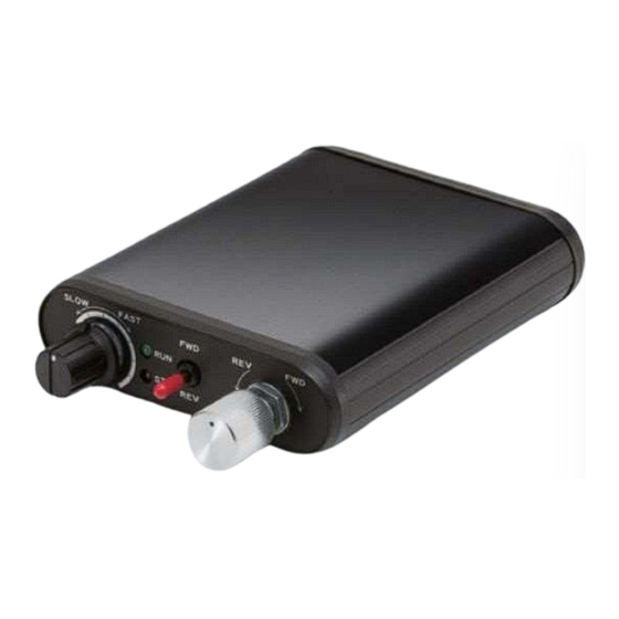
Page 5: Name And Function Of Each Part
2. Overview The SRC-101 (this device) is a dedicated controller for remote actuator drive. Micrometer-like micro-movements with possible to control the fine movement knobs and simple manual operation with JOG switches are possible. It is also actuator by connecting to a commercially available PC via a USB interface and sending commands from the PC. -
Page 6: Chapter 2 Operating The Src-101 (Manual Operation)
(1) Make sure that the power is not turned on to this device. (2) Connect the actuator to the motor connector of this device. 4-2. Connect the SRC-101 to the AC adapter Connect the dedicated AC adapter to this unit. - Page 7 • The RUN LED lights up when the actuator is operating. ・ Stops when the knob is released. 6. Alarm This device is equipped with an alarm for safety. Automatically stops actuator operation when an alarm is detected Copyright 2012, OptoSigma Inc.
-
Page 8: Overload Detection
STOP LED blinks twice per second. Turn off the power, stop using and check the load status. Chapter 3 Operating the SRC-101 with a Personal Computer (Serial Communication) 7. SRC-101 Connection Procedure 7-1. Driver installation method ( MS Window’ s example) - Page 9 (Please note that the structure of the homepage may change.) ) (3) Unzip the zip file Download example Defrosting example end of the USB cable to the (4) Connect the USB mini-B male) USB connector on the rear panel of the device. Copyright 2012, OptoSigma Inc.
- Page 10 (7) Follow the instructions in the Found New Hardware Wizard to start the driver installation. Install from a list or a specific location First, select (8) Specify the unzipped folder (9) Install USB Serial Converter IGMA ORPORATION 3210 S 92704 USA, TEL. 949-851-5881, E- OUTH RODDY ANTA ALIFORNIA MAIL SALES OPTOSIGMA...
- Page 11 USB outlet. The following describes how to change the COM port number. (1) Open Device Manager from Control Panel>System (Performance and Maintenance) > Hardware > Device Manager check the number (COM2 of the USB Serial Port in the example ) Copyright 2012, OptoSigma Inc.
- Page 12 * Do not set the port number in use. Communication with other connected devices may not be possible. Available Ports 7-3. Connect the SRC-101 to a computer Connect this device to a computer. (1) Make sure that the power is not turned on to this device.
- Page 13 Go to the machine origin of the actuator ✔ instruction Jog Operation Instructions Specifies the direction of movement of the jog ✔ motion Relative Movement Pulse Specify the relative amount of movement ✔ Number Setting Instruction Copyright 2012, OptoSigma Inc.
-
Page 14: Command Format
However, the confirmation command (Q:, !:) For commands with data return, it will be returned data instead of OK". 9-3. Command details (1) H command (machine origin return instruction) ・Command format H:1 (or H:W) ・Return data format IGMA ORPORATION 3210 S 92704 USA, TEL. 949-851-5881, E- OUTH RODDY ANTA ALIFORNIA MAIL SALES OPTOSIGMA... - Page 15 1~1000000 pulse values can be set ・Return data format " " Normal "OK Error NG" ・Explanation Set the axis of movement, direction of movement, and relative amount of movement. The G command is always after executing this instruction required Copyright 2012, OptoSigma Inc.
- Page 16 Set the current coordinates to the electrical (logical) origin. After executing this command, the coordinates are set to 0. (7)S command (speed setting instruction) ・Command format S:J n ・Parameters :1~48 ・Return data format " " Normal "OK Error NG" ・Explanation IGMA ORPORATION 3210 S 92704 USA, TEL. 949-851-5881, E- OUTH RODDY ANTA ALIFORNIA MAIL SALES OPTOSIGMA...
- Page 17 K" when the axis movement is forcibly terminated by a stop command. "B" " ACK3 returns during positioning and R" in other states. ・Command format ・Return data format 0,ACK1,ACK2,ACK3 coordinate Current coordinate value (reference value) ACK1 Command error or parameter error Copyright 2012, OptoSigma Inc.
- Page 18 ・ We will send back the commentary software version. In the , it example is Ver.1.00. ?:S command (speed check instruction) (12) ・Command format ・Return data format (example) IGMA ORPORATION 3210 S 92704 USA, TEL. 949-851-5881, E- OUTH RODDY ANTA ALIFORNIA MAIL SALES OPTOSIGMA...
-
Page 19: Chapter 4 Specifications
8bit without ・Parity 1bit ・Stop bit without ・Flow control ・Delimiter CR+LF 11. Connector Pin Assignment 11-1. MOTOR CONNECTOR number name number name Motor + Motor - Motor + Motor - Connector TCS7147-012177 (equivalent to Hosiden Corporation) Copyright 2012, OptoSigma Inc. - Page 20 11-2.USB mini-B connector number name + 5V - Data +Data Connector DX2R005HN2 (equivalent to Japan JAE Industries, Ltd.) 12. Exterior Dimensional Drawing IGMA ORPORATION 3210 S 92704 USA, TEL. 949-851-5881, E- OUTH RODDY ANTA ALIFORNIA MAIL SALES OPTOSIGMA...
Need help?
Do you have a question about the SRC-101 and is the answer not in the manual?
Questions and answers