Table of Contents
Advertisement
Quick Links
Advertisement
Table of Contents

Related Manuals for OptoSigma SHOT-102


Summary of Contents for OptoSigma SHOT-102
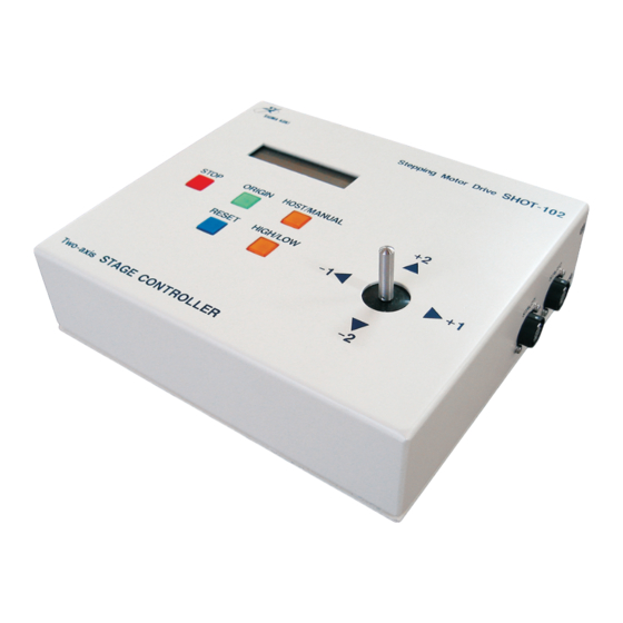
- Page 1 Joy Stick Operation Two-Axis Stage Controller SHOT - 102 User's Manual...
-
Page 2: Table Of Contents
2-4. Connection between SHOT-102 and Motorized Stage ‥‥‥‥‥‥‥‥‥‥ 10 2-5. Manual Operation of Stage with SHOT-102‥ ‥‥‥‥‥‥‥‥‥‥‥‥‥‥ 11 2-6. Connection between SHOT-102 and Host (PC, etc) and Control‥ ‥‥‥‥‥ 12 2-7. Environment Settings of Host‥ ‥‥‥‥‥‥‥‥‥‥‥‥‥‥‥‥‥‥‥‥ 12 2-8. Power ON‥ ‥‥‥‥‥‥‥‥‥‥‥‥‥‥‥‥‥‥‥‥‥‥‥‥‥‥‥‥ 13 Section 3: Commands for SHOT-102 ‥‥‥‥‥‥‥‥‥‥‥‥‥‥‥‥‥‥‥... -
Page 4: For Your Safety
■ SHOT-102 User’s Manual ■ For Your Safety ◦ Before using this product, read this manual and all warnings or cautions in the documentation provided. ◦ Only Factory Authorized Personnel should be changes and/or adjust the parts of controller. The Symbols Used in This Manual... -
Page 5: Section 1: Before Using Your Shot-102
If your package does not include all the items, or items are damaged, please contact us. □ SHOT-102 Stage Controller Unit : 1 □ AC power cable : 1 □ User'sManual (This Manual) : 1... -
Page 6: Outline
This also allows you to operate the stage with a joystick. 1-3 SHOT-102 System Diagram SHOT-102 incorporates stepping motor drivers, which enables you to design a low cost, space- efficient system with our SGSP series or other motorized stages driven by stepping motors, using standard cables for the connection. -
Page 7: Names And Functions Of Parts
■ SHOT-102 User’s Manual ■ 1-4 Names and Functions of Parts Upper Panel Functions ① Indicates each axis coordinate value, controller's motion mode and so on. ② Moves the stage to its machine home position in manual mode The LED indicator lights up when both axes are at the home position. - Page 8 ⑧ Connect the cable when using your PC for controlling via the GP-IB interface. ⑨ Connect the cable when using your PC for controlling via RS-232C interface. ⑩ Makes basic settings for your SHOT-102. ⑪ Makes basic settings for your SHOT-102.
- Page 9 ■ SHOT-102 User’s Manual ■ Right Side Panel Connect the stage used as Axis 1. Connect the stage used as Axis 2. Display (example display for explanations and not representing actual operational status) Displays either of host (displayed as "H")/manual ("M") modes.
-
Page 10: Section 2: Basic Operations
DIP switch settings and current adjustments (RUN/STOP) for each axis motor. 2-2 Set Parameters with DIP Switch Make basic settings of your SHOT-102 by setting switches on the DIP switches to ON/OFF. The side marked with " ・ " is switch 1. - Page 11 ■ SHOT-102 User’s Manual ■ List of DIP Switch Settings (Set to ON by turning to the number-marked side on the switch body) DIP Switch 1 Items DIP switch No. Descriptions CR+LF(EOI) Delimiter CR(EOI) LF(EOI) Interface GP-IB RS232C 38400 Baud rate...
- Page 12 ■ SHOT-102 User’s Manual ■ Differences between SHOT-102/MINI-5P modes SHOT-102 can select SHOT-102 or MINI-5P mode by DIP switch settings. Operations and commands/parameters vary depending on modes. SHOT-102 mode (factory settings) ・ On turning ON the power, “SHOT” is displayed on the LCD.
-
Page 13: Adjust Drive (Run, Stop) Current
② Connect the cable to motorized stages. Select cables correctly matching to your SHOT-102 and stages. MINI-CA or MINIS-CA series cables are applicable to SHOT-102. ③ Connect the cable from the stage for Axis 1 to STAGE 1 connector on SHOT-102. Connect the cable from the Axis 2 stage to STAGE 2. -
Page 14: Manual Operation Of Stage With Shot-102
MINI RS232C 9600 DELIMITER = CR+LF SHOT-102 is turned ON and the opening message like above is displayed on the LCD for about three seconds (the contents of the message vary depending on the settings). Then the LEDs of the HOST/MANUAL and ORIGIN switches light up and the coordinate values of the Stage 1 and 2, etc. are displayed on the LCD. -
Page 15: Connection Between Shot-102 And Host (Pc, Etc) And Control
③ Set the baud rate interface (selecting RS232C for this explanation) and delimiter (selecting CR+LF(EOI) for this explanation) by DIP switch 1 on the body. ④ Insert the male connector of the communications cable into the RS232C terminal on the SHOT-102. ⑤ Insert the female end into the serial port on your PC. -
Page 16: Power On
■ SHOT-102 User’s Manual ■ 2-8 Power ON When you have completed procedures above, connect firmly the power cord attached to SHOT-102, and insert the power plug into the receptacle. Turn ON the power switch (turn to mark). SHOT- “... -
Page 17: Section 3: Commands For Shot-102
"0." In SHOT-102 mode, axis traveling speed is depending on the speed settings by switches 9 and 10 on DIP Switch 1 and the "D" command. In MINI-5P mode, each axis moves at the following constant conditions: minimum speed (S): 500 pps, maximum speed (F): 5000 pps, acceleration/deceleration time (R): 200 ms. - Page 18 ■ SHOT-102 User’s Manual ■ ―――――――――――――― <Detecting the Mechanical Origin >―――――――――――――― MINI system When the command is given to detect the mechanical origin, the (F) Operating speed Stage stage begins moving clockwise (i.e., in the - direction) at the CW(−) (F)...
- Page 19 ■ SHOT-102 User’s Manual ■ (3) A command: Absolute Value Moving Command Function: A command that specifies stage movement destination with a coordinate absolute value. After executing this command, make sure to add the driving command, “G.” When the H, R, M, A J, L, E or C command is executed before the G command execution, the latest settings specified by the A command immediately before are canceled.
- Page 20 (9) D Command: Command to Set Speed Function: On turning ON the power, SHOT-102 will default a minimum speed (S), maximum speed (F), and acceleration/deceleration time (R), all set by switches 9 and 10 on DIP Switch 1 for each speed range. If you want to change these initial settings, use the D command.
- Page 21 ■ SHOT-102 User’s Manual ■ (10) C Command: Motor Free/Hold (Deenergize/Energize) Command Function: Deenergizes (motor free) or Energizes (hold) the motor. Execute this command to move (rotate) stages manually. Once executed, the actual stage position does not coincide with the coordinate value being displayed.
-
Page 22: Section 4: Specifications
■ SHOT-102 User’s Manual ■ Section 4: Specifications 4-1 General Specifications Power Source : 100 VAC, 50/60 Hz, 50VA Operating Temperature : 5 to 40 °C Ambient Humidity : 20 to 85% RH (without condensation) Storage Temperature : -20 to 60 °C Outer Dimensions : 200 W x 52 H x 172 D (in mm) ※... -
Page 23: Performance Specifications
■ SHOT-102 User’s Manual ■ 4-2 Performance Specifications Number of Controllable Axes : 2 axes (maximum) Coordinate setting Range : +/- 16777124 pulses Maximum Display Range : 8-digit (including sign/decimal point) x 2 lines Minimum Driving Frequency : 1 pps... - Page 24 1-19-9, Midori, SIGMA KOKI Tokyo Head office, Sumida-ku, Tokyo 130-0021, JAPAN Tel : + 81-3-5638-8228 Fax : + 81-3-5638-6550 E-mail:international@sigma-koki.com Osaka Branch 4-9-28, Nishi-Nakajima, Yodogawa-ku, Osaka 532-0011, JAPAN Tel : + 81-6-6307-4835 Fax : + 81-6-6307-4834 E-mail:sales.osaka@sigma-koki.com Kyushu Sales office 3-17, Hie-machi, Hakata-ku, Fukuoka-shi, Fukuoka 812-0014, JAPAN Tel : + 81-92-481-4300 Fax : + 81-92-481-4310 E-mail:sales.kyushu@sigma-koki.com 1-1 Yatsukaho, Hakusan-shi, Ishikawa 924-0838, JAPAN 2015.12. Fourth edition...
Need help?
Do you have a question about the SHOT-102 and is the answer not in the manual?
Questions and answers