
Related Manuals for OptoSigma GSC-02A


Summary of Contents for OptoSigma GSC-02A
- Page 1 Intelligent Driver Intelligent Driver Two-Axis Stage Controller GSC - 02A GSC - 02A User's Manual User's Manual...
- Page 2 Notes regarding these materials ・ These materials are intended as a reference to assist our customers in the use of the SIGMA- KOKI CO., LTD. Product best suited to the customer’s application; they don’t convey any license under any intellectual property rights, or any other rights, belonging to SIGMAKOKI CO., LTD.
-
Page 3: Table Of Contents
4. Parts of the GSC-02A ……………………………………………………………… 5 Chapter 2 Basic Operations ……………………………………………… 6 5. GSC-02A Connection procedure ………………………………………………… 6 6. GSC-02A Setting ……………………………………………………………………… 7 Chapter 3: Using GSC-02A to position Motorized Stages …… 9 7. Using Computer to position Motorized Stages … ……………………………… 9 Chapter 4: Specification ………………………………………………… 23 8. Specification ………………………………………………………………………… 23 ... -
Page 4: For Your Safety
■ GSC-02A ■ User's Manual For your safety Before using this product, read this manual and all warnings or cautions in the documentation provided. Only Factory Authorized Personnel should be changes and/or adjust the parts of controller. The symbols used in this manual... -
Page 5: Chapter 1: Before You Begin
1. Package Contents Purchasers of the Stage Controller should find that the package contains the items listed below. Check the package contents using the following checklist. Contact your retailer as soon as possible in the event that you should find that any item is missing or damaged. □ GSC-02A Stage Controller □ User’ s Manual (This Manual) □ SJT-02 Terminal Cap You can download sample software from our web page. -
Page 6: Overview
■ GSC-02A ■ User's Manual 2. Overview This controller is two axes stage controller featuring stepping motor drivers. When the GSC-02A is connected to an ordinary personal computer via an RS232C interface, the stage can be accurately moved to the desired position by simple commands sent from the PC. In addition, manual operation is possible by connecting SJT-02 (an optional product). 3. The GSC-02A System OSMS20/26 series D15D15A-CA Cable OSMS40ZF/60ZF series SGSP40/60YAW series D15RP-CA GSC-02A OSMS40/60YAW series Cable RS232C/STR SGSP-A/B series Cable TSDM series SGSP-ACT series OSMS-40 series D15RP-CA Cable SJT-02 TAMM series OSMS-60 series HPS series HDS series Figure3-1: The GSC-02A system Note that applicable cables and drive current values are depending on the ... -
Page 7: Parts Of The Gsc-02A
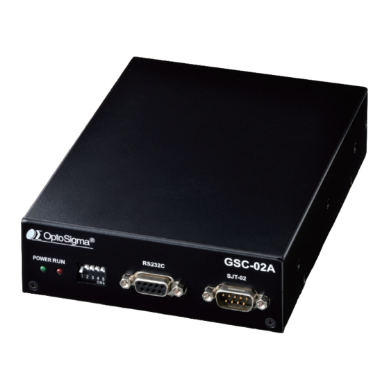
■ GSC-02A ■ User's Manual 4. Parts of the GSC-02A SJT-02 ①POWER LED ②RUN LED ③DIP switch ④RS232C connector ⑤SJT-02 connector Figure4-1: GSC-02A front panel ⑧Earth terminal ⑨Power terminal ⑥Stage driving connector (Axis 1) ⑦Stage driving connector (Axis 2) Figure4-2: GSC-02A rear panel Functions: ① POWER LED : Lights up in green when powered. ② RUN LED : Lights up in red while driving stages. ③ DIP switch : Makes basic settings for GSC-02A. ④ RS232C connector: : This connector is used when the device is controlled from the computer via an ... -
Page 8: Chapter 2 Basic Operations
③ Insert the male connector of communications cable into the RS232C connector on the GSC- 02A. Insert the female end into the serial port on your PC. Connect to the peripheral device (SJT-02) using the SJT-02 dedicated accessory cable. ① Please confirm the power source is turning off. ② Connect the attached cable for SJT-02 to the SJT-02 connector on GSC-02A. Connect the female side to the SJT-02. ③ Set the baud rate of the GSC-02A by adjustment on the DIP switch. SJT-02 can’ t use on the baud rate set to 2400 [bps]. -
Page 9: Gsc-02A Setting
■ GSC-02A ■ User's Manual 6. GSC-02A Setting Initialize your GSC-02A to match to the target stages and host environment (your PC, etc.). The initialization includes DIP Switch settings and current adjustments (RUN/STOP) for each axis motor. 6-1. Set parameters with DIP Switch Initialize your GSC-02A by setting each switch to ON/OFF as follows: Parameter Assignment in the DIP Switch: Table6-1-1: DIP switch setting items DIP Switch No. Items Parameters Baud rate 2400 / 4800 / 9600 / 19200 Detecting the mechanical origin MARK method / MINI method Input logic for the limit sensor Normal open/ Normal close Specify whether to return mechanical origin First axis only/ Both axis for each axis Switch settings and Corresponding Parameters (Set to ON by turning to the downside) Table6-1-2: DIP switch setting list... - Page 10 ■ GSC-02A ■ User's Manual 6-2. Setting the drive current Set current values supplied from GSC-02A to stages. Turn a RUN current volume, provided on the side of the unit, to adjust RUN current corresponding to the stages to use. Use a STOP current volume to set a ratio to RUN current according to your conditions for the case where the current down function works. You can make each current adjustment for Axis 1 or Axis 2 independently. Volume Note that for the STOP current, adjustment is available not for current ...
-
Page 11: Chapter3: Using Gsc-02A To Position Motorized Stages
■ GSC-02A ■ User's Manual Chapter3: Using GSC-02A to position Motorized Stages 7. Using Computer to position Motorized Stages The controller can be connected to a computer using an RS232C interface. Motorized stages can then be precisely controlled by commands (strings) transmitted from the computer. The RS232C interface communication parameter of the GSC-02A is described below. Please set the configurations of the PC side according to the following Table7-1. Table7-1: RS232C communication settings Items Descriptions Baud rate Baud rate set with DIP Switch... - Page 12 ■ GSC-02A ■ User's Manual The following commands are available only when System Type B is set. (The settings are retained even when the power is turned off.) Table7-1-2: Command list (System Type B) Direction of travel DR: Select the + direction Input logic for the limit sensor LSL: Select the detection logic for the limit sensor Input logic for the ORG sensor OSL: Select the detection logic for the ORG sensor Input logic for the NEAR sensor NSL: Select the detection logic for the NEAR sensor Method of return to origin ORG: Select the method of return to origin Switch number of steps S: Switch number of steps Communication protocol ACK: Select the communication protocol ORG speed settings B: Set S, F and R of ORG Note) When stage operating status is Busy, if you send other command of L:, Q:, !:, ?:, command status is NG. 7-2. Command Format Except for some status check commands (Q:, !:, ?:), no response will be returned to a command input. To determine whether or not a command was received normally, use the Q command to ...
- Page 13 ■ GSC-02A ■ User's Manual 7-3. Command in detail (1) H command: Return to mechanical origin Features: This command is used to detect the mechanical origin for a stage and set that position as the origin. Once the mechanical origin has been detected, the value displayed will ...
- Page 14 ■ GSC-02A ■ User's Manual (3) A command: Set number of pulses for absolute travel Features:This command is to specify the-axis of travel, direction, and the travel (number of pulses). This command must always be followed by a drive G command. Travel is by means of acceleration /deceleration driving. ・Command format A:nmPx ・parameter n: 1 or 2 or W 1: first-axis, 2: second-axis, W: both first-axis and second-axis m: + or - ...
- Page 15 ■ GSC-02A ■ User's Manual (5) G command: Drive Features: When a drive command is issued, the stage starts moving, moves the specified number of pulses, and then stops. The G command is used after M, A, and J commands. ・Command format G: Drive G Drive (It works with just G without the colon) Note) During stage operating status is Busy, the command status is NG. Note) During motor excitation off by C command, motorized stages can't move, and the command status is NG. (6) L command: Decelerate and stop Features: When this command is executed, the stage decelerates and stops. ・Command format L:n ・parameter n: 1 or 2 or W 1: first-axis, 2: second-axis, W: both first-axis and second-axis Ex1) L:1 First-axis decelerates and stops Ex2) L:W ...
- Page 16 ■ GSC-02A ■ User's Manual (9) D command: Speed settings1 Features: The minimum speed (S), maximum speed (F), and acceleration/deceleration time (R) are set according to the initialize settings when the power is turned on. This command allows you to change these default settings. The default settings are (S): 500 [pps], (F): 5000 [ps], (R): 200 [ms]. ・Command format D:nSspdsFspdfRspdr ・parameter n: 1 or 2 or W 1: first-axis, 2: second-axis, W: both first-axis and second-axis spds: Minimum speed (S) 1 to 30000 [pps] spdf: Maximum speed (F) 1 to 30000 [pps] spdr: Acceleration/deceleration time (R) ...
- Page 17 ■ GSC-02A ■ User's Manual Acceleration and Deceleration Patterns Maximum pulse speed (F) Number of Minimum pulse pulses moved speed (S) Acceleration Deceleration time (R) [ms] time (R) [ms] Positioning time Figure7-3-1: Acceleration and Deceleration Patterns (11) C command: Free/ hold motor (Excitation ON/OFF) Features: This command is used to excite the motor or to turn excitation off, making it possible ...
- Page 18 ・parameter p:Parameter watch below the table n: 1 or 2 or W 1: first-axis, 2: second-axis, W: both first-axis and second-axis When you use (V,-,N,ACK) parameter, n don’ t need. Parameter Data returned Examples Version numbers Ex)?:V → V1.00 - Sub version numbers Ex)?: -→ 001 Ex)?:N → GSC-02A (System Type A) Device name GSC-02B (System Type B) 0 or 1 Ex)?:DRW → 0,0 Ex)?:DR2 → 0 Direction of travel 0: POS,1:NEG 0 or 1 Ex)?:LSLW → 0,0 Ex)?:LSL2 → 0 Input logic for the limit sensor 0: Normal Close,1: Normal Open 0 or 1 Ex)?:OSLW → 0,0 Ex)?:OSL2 → 0 Input logic for the ORG sensor 0: Normal Close,1: Normal Open Input logic for the NEAR 0 or 1 Ex)?:NSLW → 1,1 Ex)?:NSL2 → 1 sensor 0: Normal Close,1: Normal Open...
- Page 19 ■ GSC-02A ■ User's Manual (15) SYS command: Switching systems Features: This command is used to set the System Type A or B. The default setting is 0. System Type A: S et method of return to origin, input logic for the limit sensor, specify whether to return mechanical origin for each axis with DIP switches. System Type B: S et method of return to origin, input logic for the limit sensor, specify ...
- Page 20 ■ GSC-02A ■ User's Manual (17) LSL command: Detection logic for the limit sensor (Enabled only for System Type B) Features: Select the conditions (input logic) for the limit sensor for each-axis. The default setting is 0. ・Command format LSL:na ・parameter n: 1 or 2 or W 1: first-axis, 2: second-axis, W: both first-axis and second-axis a: 0 or 1 0 : Normal close (switches OFF from the default value of ON when limit sensor is detected) 1 : (switches ON from default value of OFF when limit sensor is ...
- Page 21 ■ GSC-02A ■ User's Manual (19) NSL command: Detection logic for the NEAR sensor (Enabled only for System Type B) Features: Select the conditions (input logic) for the NEAR sensor for each-axis. The default setting is 0. ・Command format NSL:na ・parameter n: 1 or 2 or W ...
- Page 22 ■ GSC-02A ■ User's Manual Detecting the Mechanical Origin: MINI method CW sensor ORG SPEED(F) CW(−) CW LS detection ORG SPEED(F) CCW(+) Move 1000 pulse ORG SPEED(S) CW(−) CW LS detection ORG SPEED(F) CCW(+) Move 1000 pulse CCW(CW) sensor CW(CCW) sensor CENTER method ORG SPEED(F) CW(−) CW LS detection ORG SPEED (S) CCW (+) Move 1000 pulse ORG SPEED(S) CW(−) CW LS detection ORG SPEED(F) CCW(+) CCW LS detection ORG SPEED(S) CW(−) Move 1000 pulse ORG SPEED(S) CCW(+) CCW LS detection ORG SPEED(S) CW(−) Move middle of CW/CCW LS Middle of LS ORGS method ORG sensor...
- Page 23 ■ GSC-02A ■ User's Manual NORM method NEAR sensor ORG sensor CW(CCW) sensor ORG SPEED(S) N sensor detection 1/10 ORG SPEED(S) O sensor detection Note) If the stage moves in the CW direction and the NEAR sensor can’ t detect it (no NEAR sensor), the stage will stop at the CW sensor. Note) If the stage moves in the CW direction after detecting the ORG sensor and the ORG sensor can’ t be detected (no ORG sensor), it’ ll stop at the CW (CCW) sensor. MARK method ORG sensor...
- Page 24 ■ GSC-02A ■ User's Manual (22) ACK command: Communication protocol Features: This command is used to specify whether the controller will return OK/NG in response to command signals sent from the computer. The default setting is 0. ・Command format ACK:a ・parameter a: 0 or 1 0: SUB: Don’ t return OK / NG when using interface 1: MAIN: Return OK / NG when using interface Ex) ACK:1 Set to MAIN (Return OK / NG) Note) During stage operating status is Busy, the command status is NG. (23) B command: ORG speed settings Features: This command is used to change the return speed to the origin. The default settings ...
-
Page 25: Chapter 4: Specification
■ GSC-02A ■ User's Manual Chapter 4: Specification 8. Specification (1) General specifications Power source DC+24 [V] Rating current 2 [A] Operating temperature 5 ~ 40 [℃ ] Storage temperature -20 ~ 60 [℃ ] Ambient humidity 20 ~ 80 [%RH] (no condensation) Altitude up to 2000 [m] Indoor use only Installation category Ⅱ Pollution degree External dimensions 180W × 125D × 40H (excluding projections) [mm] Weight ... - Page 26 ■ GSC-02A ■ User's Manual (3) Driver Specifications Driver Mode Half step/Full step driving Driving (RUN) current 0.25 [A/phase] to 0.8 [A/phase] Current down function Automatic current down (4) Electrical fast transmit/burst immunity EN61000-4-4 (2012) Level2 (5) Electrostatic discharge EN61000-4-2 (2009) Level2. Osaka branch...
-
Page 27: Connector Pin Numbers And Signals
■ GSC-02A ■ User's Manual 9. Connector Pin Numbers and Signals 9-1. STAGE1,2 connector Name Name Blue: motor wiring GND: for Brake Red: motor wiring +24 [V]: for Brake Orange: motor wiring LS ( + ): limit detection on + Green: motor wiring LS ( - ): limit detection on - Black: motor wiring GND: common sensor GND: common sensor NEAR: proximity detection ORG: mechanical origin detection +24 [V]: sensor power supply +24 [V]: sensor power supply Connector Type D-sub 15pin female connector (mm screw threads) 9-2. RS232C connector Name Name -... -
Page 28: Exterior Dimensions
■ GSC-02A ■ User's Manual 10. Exterior Dimensions 3-M3×0.5 Depth4 Osaka branch... - Page 30 1-19-9, Midori, SIGMA KOKI Tokyo Head office, Sumida-ku, Tokyo 130-0021, JAPAN Tel : + 81-3-5638-8228 Fax : + 81-3-5638-6550 E-mail:international@sigma-koki.com Osaka Branch 4-9-28, Nishi-Nakajima, Yodogawa-ku, Osaka 532-0011, JAPAN Tel : + 81-6-6307-4835 Fax : + 81-6-6307-4834 E-mail:sales.osaka@sigma-koki.com Kyushu Sales office 3-17, Hie-machi, Hakata-ku, Fukuoka-shi, Fukuoka 812-0014, JAPAN Tel : + 81-92-481-4300 Fax : + 81-92-481-4310 E-mail:sales.kyushu@sigma-koki.com 1-1 Yatsukaho, Hakusan-shi, Ishikawa 924-0838, JAPAN 2021.11. First edition...
Need help?
Do you have a question about the GSC-02A and is the answer not in the manual?
Questions and answers