Table of Contents
Advertisement
Quick Links
Advertisement
Table of Contents

Related Manuals for OptoSigma JD-101


Summary of Contents for OptoSigma JD-101
- Page 1 SC29101-K13-18002 JOG DIAL CONTROLLER JD-101 User’s Manual...
- Page 2 SC29101-K13-18002 Notes regarding these materials ・ These materials are intended as a reference to assist our customers in the use of the SIGMAKOKI CO., LTD. Product best suited to the customer’s application; they do not convey any license under any intellectual property rights, or any other rights, belonging to SIGMAKOKI CO., LTD.
- Page 3 SC29101-K13-18002 For Your Safety Before using this product, read this manual and all warnings or cautions in the documentation provided. Only Factory Authorized Personnel should be changes and/or adjust the parts of controller. The Symbols Used in This Manual WARNING CAUTION This symbol marks warnings that should be read...
- Page 4 SC29101-K13-18002 Disclaimer of Liability ① SIGMAKOKI CO., LTD. does not accept liability for damages resulting from the use of this product or the inability to use this product. ② SIGMAKOKI CO., LTD. does not accept liability for damages resulting from the use of this product that deviates from that described in the manual.
-
Page 5: Table Of Contents
SC29101-K13-18002 table of contents Chapter 1: Before You Begin ...................... 6 1-1. Overview..........................6 1-2. Connecting method ......................7 Chapter 2: Notes on Use ......................7 2-1. Name of each part ......................7 2-2. Operating method ......................8 Chapter 3: Specifications ......................10 3-1. -
Page 6: Chapter 1: Before You Begin
This means that the joystick allows you to work near the motorized stage while checking its behavior even if the controller and the motorized stage are away from each other. When you use JD-101, you can use when Table1-1 controller version. Table1-1... -
Page 7: Connecting Method
This product is connected to the controller with MDR14-CA cable. ① Connect a standard cable (MDR14-CA-*) to the connector on the rear panel of the JD-101. ② Connect the cable from the JS-301 to the “JOYSTICK” or “OPTION”of the connector on the front panel of the SHOT-30X series and PGC-04-U controller. -
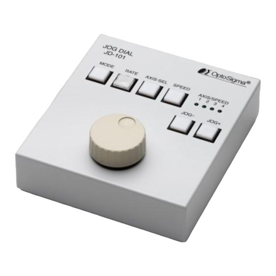
Page 8: Operating Method
SC29101-K13-18002 2-2. Operating method ①【MODE】button Change an operation mode of the controller. HOST→MANUAL・・・ Refer to a User’s Manual of SHOT-302GS/SHOT-304GS for various modes. NOTE) IN SHOT-702/PGC-04-U/HSC-103, the MODE change is invalid. ②【RATE】button Switch the amount of movement of the stage for the dial operation. The LED indicator lights up : 5pulse/ 1click for JOG-dial.(High-RATE) The LED indicator lights down: 1pulse/ 1click for JOG-dial.(Normal-RATE) ③【AXIS-SEL】button... - Page 9 SC29101-K13-18002 ④【SPEED】 button Cycle through “SPEED 1/2/3/4” settings stored in controller’s memory switches (1→2→3→4→1・・・). When "●" position means Shining LED. Number of Shining AXIS/SPEED LED means speed value. ●〇〇〇 SPEED=1 ●●〇〇 SPEED=2 ●●●〇 SPEED=3 ●●●● SPEED=4 Fig.2-2-2 Number of Shining AXIS/SPEED LED means speed value. After about 3 seconds, the AXIS / SPEED LED on the selected axis is light on.
-
Page 10: Chapter 3: Specifications
SC29101-K13-18002 Chapter 3: Specifications 3-1. Specifications Power supply Supplied from the controller via connection cable Operating temperature 5~40℃ Storage temperature -20~60℃ Altitude up to 2000m Indoor use only Ⅱ Installation category Pollution degree Ambient humidity 20~80%RH (no condensation) External dimensions 130W×145D×56H [mm](excluding projections) Weight[kg] About 0.6 [kg] However, it does not include cables... -
Page 11: Exterior Dimensions
SC29101-K13-18002 3-3. Exterior Dimensions Fig.3-3 Exterior Dimensions -11-... - Page 12 SC29101-K13-18002 SIGMAKOKI CO., LTD. http://www.global-optosigma.com Tokyo Head office SIGMAKOKI Tokyo Head office 1-19-9, Midori, Sumida-ku, Tokyo 130-0021, JAPAN TEL:+81-3-5638-8228 FAX:+81-3-5638-6550 E-mail:international@sigma-koki.com Osaka Branch 4-9-28, Nishi-Nakajima, Yodogawa-ku, Osaka 532-0011, JAPAN TEL:+81-6-6307-4835 FAX:+81-6-6307-4834 Kyushu Sales office 3-17, Hie-machi, Hakata-ku, Fukuoka-shi, Fukuoka 812-0014, JAPAN TEL:+81-92-481-4300 FAX:+81-92-481-4310...
Need help?
Do you have a question about the JD-101 and is the answer not in the manual?
Questions and answers