Table of Contents
Advertisement
Quick Links
Advertisement
Table of Contents

Subscribe to Our Youtube Channel
Related Manuals for Dantherm Silencio 600


Summary of Contents for Dantherm Silencio 600
- Page 1 Silencio Service manual No. 018717 • ver. 1.1 • 23.01.2007...
- Page 2 Der tages forbehold for trykfejl og ændringer Dantherm can accept no responsibility for possible errors and changes Irrtümer und Änderungen vorbehalten Dantherm n’assume aucune responsabilité pour erreurs et modifications éventuelles...
-
Page 3: Topic See Page
Introduction Overview This is the service manual for the Dantherm Air Handling Silencio unit. Introduction The table of content below gives you an overview of the main sections. Please see the complete table of content for further information about the sections. -
Page 4: Table Of Contents
Table of content This is the complete table of content covering all sections in this service manual. Introduction Each main section will begin with an introduction including a separate table of content covering the exact section. This service manual covers the following topics: Table of content Topic See page... - Page 5 Table of content, continued Table of content, Topic See page continued How to replace the compressor contactor How to replace the heater contactor How to replace the EPROM How to replace the phase reversal monitor How to replace the thermostat for the heating element How to replace parts of the cooling system Fault finding guide Service agreement...
-
Page 6: General Information
Copying of this service manual, or part of it, is not allowed without written permission Copyright from Dantherm Air Handling A/S. The service manual is subject to changes without notice. Reservations Dantherm Air Handling A/S, Marienlystvej 65, DK-7800 Skive hereby declare that the CE-Declaration of units mentioned below: Conformity 365006 Silencio 600 3 ×... -
Page 7: Definitions
Definitions This section gives you a definition of some of the technical words and terms used in this Introduction manual. Here you have the list of words and terms with the matching definition: List Term Definition Return air (T Internal air entering the ACU Ambient air (T External air entering the ACU Exhaust air (T... -
Page 8: Product Description
Product description Overview This section will give you a description of the Silencio and its functionality. Introduction This section covers the following topics: Content Topic See page General description next page Description of parts Description of the control board Functional description Set points Control strategy... -
Page 9: General Description
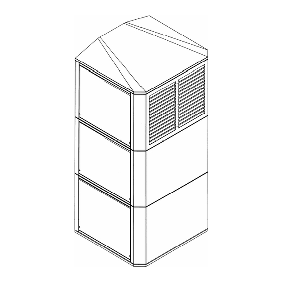
Silencio is designed to be mounted outdoor. Silencio is available in the 4 sizes: Versions • Silencio 600, 6 kW • Silencio 800, 8 kW • Silencio 1000, 10 kW • Silencio 1400, 14 kW... - Page 10 General description, continued This illustration gives an overview of the parts and systems, a more detailed description Illustration, will follow in the section “Description of parts”, on page 11: external Part Part Temperature sensors, see section External condenser fan “How to replace the temperature Control board sensors”, page 56 Filters...
-
Page 11: Description Of Parts
Description of parts This section will give you a more detailed description of the parts of the Silencio. Introduction The parts that will be described are: • Temperature sensors • Compressor • Filters • Heater • Damper • Control board •... - Page 12 Description of parts, continued The internal fan draws return air from the shelter into the Silencio, to: Internal fan • Circulate the internal air, when the return temperature is not too high (Recycle) • Draw out the return air and push it through the air condition system to cool the air (active cooling) •...
- Page 13 Description of parts, continued The 25 poled SUB-D connection gives you the possibility of connecting additional 25 poled SUB-D, external equipment (see table below). connections Furthermore you have the same functionality as the RS485 communication port, for details about this, see section “Description of the control board”, page 14. Warning! A male Sub-D 25 connector with a connection between 5 and 12 is mounted on the female Sub-D 25 connector.
-
Page 14: Description Of The Control Board
Description of the control board This section gives you a detailed description of the control board and its test function. Introduction Description of how to change settings is to find in section “Users guide”, page 31. All Silencios are provided with a DanCon control board. DanCon This drawing illustrates the control board: Illustration... - Page 15 If any fail is detected during the test, the LED will flash with a frequency of 1 Hz for 30 seconds after the test is done to indicate some fault were detected. Here are the test points for the Silencio 600: Test points,...
- Page 16 Description of the control board, continued Here are the test points for the Silencio 800, 1000 and 1400: Test points, Silencio 800, 1000 and 1400 IDLE Closing Stopped Stopped Stopped Jingle 30 sec. Heating Closing 700 RPM Stopped Stopped Normal 90 sec.
-
Page 17: Functional Description
Functional description Silencio operates with 2 systems and in 7 different modes. Introduction The 2 systems, which are described in the following, are: • Air conditioning system • Heating system The 6 modes, which are described in the following, are: •... - Page 18 Accessories, continued In free cooling mode the damper, the Free cooling internal fan and the external fans will operate to provide exactly the fresh air amount needed to keep a constant temperature in the shelter/room (3 degrees below the cooling set point).
- Page 19 Accessories, continued Emergency cooling will occur when Emergency there is either compressor fault or loss cooling of AC power. Since active cooling is not possible, the damper will attempt to provide fresh air cooling to keep the return temperature 3 degrees below set point even when it is not possible because of high ambient temperatures.
-
Page 20: Set Points
Set points This section gives you information about the set points. Introduction The following topics will be described: • Factory settings • How to change set points This section describes how to change set points on a stand alone unit without any of General the accessories DanView or DanLink. -
Page 21: Control Strategy
Control strategy The control strategy ensures the best mode of operation at all times. Introduction Measurements of ambient, supply, return and condensing temperatures decides the specific settings for fans, damper, heater and compressor. The control board contains a programmable CPU with adjustable settings according to the exact requirements. - Page 22 Control strategy, continued Strategy, continued Temp. Temp. Action °C °C Action sensor sensor Condenser fan will increase speed Condenser 48 °C by 30 RPM each 30 seconds as long as condenser is 1 or more degrees above 47 °C until maximum 1400 RPM is reached Condenser fan speed constant Condenser...
-
Page 23: Get Ready For Use
Get ready for use Overview This section contains information about unwrapping, mounting, installation and starting Introduction up of the unit. This section covers the following topics: Content Topic See page Unwrapping next page Mounting Installation and starting... -
Page 24: Unwrapping
Unwrapping This section will guide you through the unwrapping of the Silencio unit. Introduction Do not remove the male SUB-D plug on the front of the unit! Important! Follow these steps to unwrap the unit: Procedure Step Action Remove all the cardboard and the plastic bag from the unit and throw it away Please check the content when having received and unwrapped the Silencio unit. -
Page 25: Mounting
If, in spite of these reservations, customers choose to mount the units on the containers before these have been finally placed, Dantherm Air Handling cannot be held responsible for whatever complications might arise. Before you start Make sure you have the following available before you start mounting: •... - Page 26 Mounting, continued Procedure, Step Action continued Cut the slot and throw away the plate that has just been cut out Drill the holes for the wall brackets and mount them on the shelter according to the measures on the drawing above by using 4 bolts M8 × 250 mm (enclosed) Wall bracket Remove the two upper side covers...
- Page 27 Mounting, continued Procedure, Step Action continued, continued Seal the unit on the back with the enclosed gasket to make sure there are no leaks between the shelter and the unit. The sealing must be placed all around at the outside edge of the unit Gasket Lift up the unit and place it very carefully on the two wall brackets...
- Page 28 Mounting, continued Procedure, Step Action continued Seal the top of the unit with fluid sealant Loosen the pallet underneath the Silencio unit by removing the 2 mounting brackets in each side of the unit. Be careful when the pallet falls down Mount the two support brackets on the wall brackets by tightening the:...
- Page 29 Mounting, continued Procedure, Step Action continued Adjust perpendicular position to the unit by using the adjustment screws (enclosed) Remove the left, lower side cover and lead out the drainage hose Remount the all the covers Mounted Silencio...
-
Page 30: Installation And Starting
Installation and starting This section will guide you through the installation and the starting of the Silencio. Introduction Make sure you have the following available before you start the installation: Before you start • Tools for wire connections This drawing shows you the electrical connections: Illustration Follow these steps to install the unit: Procedure... -
Page 31: Users Guide
Users guide Overview This section only describes how to activate/use the different functions. Introduction Under each of the functions below, you will find relevant references if further information is needed. You can test all functions in the Silencio by pushing a sharp object against the test Test button. -
Page 32: Service Guide
All requests for information, service or parts should include serial number. Serial numbers Product model and serial numbers are available from the nameplate, which is located next to the control board. Dantherm Air Handling model number: • Silencio, 600 kW 365006 • Silencio, 800 kW 365008 •... -
Page 33: Preventive Maintenance
Dantherm Air Handling recommend that intervals between preventive maintenance do Interval not exceed 6 months. It is also our recommendation that the site and unit is examined closely during the first preventive maintenance to determine whether the interval is too long. - Page 34 Preventive maintenance, continued The recommended approach when performing a preventive maintenance visit is: Recommended approach Step Action Make sure that the power to the unit is safely switched of Clean the unit carefully: • Air ducts • Fans • Filters •...
-
Page 35: Accessories
Additional information is available on each accessory, please contact Dantherm Air Handling A/S. Here is the complete list with drawing, description and part number for all available... - Page 36 Preventive maintenance, continued Tasks, continued Accessory Illustration Description Part no. Hot spot This is an extra temperature 016364 sensor sensor to be placed in the critical spot of the shelter. The operation of the climate unit will then be controlled in accordance with the highest value of either the return air or hot spot sensor.
- Page 37 DanLink is a telemonitoring Hardware: system designed for remote surveillance and change of set 012580 points. 012581 Software: 017499 DanView The DanView is a display unit for 012958 monitoring relevant parameters in connection with the Dantherm Air Handling standard shelter cooling units.
-
Page 38: Spare Parts
Spare parts Overview This section gives you a list of all available spare parts and under which number, they Introduction should be ordered. Furthermore the section contains an instruction in replacing the spare part. This section contains the following topics: Contents Topic See page... -
Page 39: Spare Parts List
Spare parts list Here you have the complete list of spare parts with part numbers: List Spare part Model Part number VDI filter 296074 Internal fan 296076 External fan 296077 Control board 296084 Recycle timer 296093 Dry filter 296080 Compressor 600/800 –... -
Page 40: How To Replace The Vdi Filter
The filter only needs to be replaced when it is faulty, very filthy or as a part of the When to replace preventive maintenance. Dantherm Air Handling A/S recommends a replacement of the VDI filter in a maximum interval of 6 months. - Page 41 How to replace the VDI filter, continued Follow these steps to replace the filter: Procedure, internal side Step Action Switch of all the power to the unit Grip carefully the lamellas with both hands from the inside, (or from the outside after having removed one of the lower side covers –...
-
Page 42: How To Replace The Internal Fan
How to replace the internal fan The internal fan circulates the indoor air. Product description The internal fan only needs to be replaced when it is faulty or as a part of a long time When to replace replacement plan, e.g. after approximately 5 years. The internal fan can be ordered under part number 296076. - Page 43 How to replace the internal fan, continued Follow these steps to replace the internal fan: Procedure Step Action Switch of all the power to the unit Remove the upper left side cover by unscrewing the two torx 25 screws that hold it in place Disconnect the white 4-poled AMP-plug with a small tug Pull out the defect internal fan box...
-
Page 44: How To Replace One Of The External Fans
How to replace one of the external fans The external fans remove surplus heat from the condenser when the active cooling Product mode is active. description The external fans only need to be replaced when they are faulty or as a part of a long When to replace time replacement plan, e.g. - Page 45 How to replace one of the external fans, continued Follow these steps to replace the external fan: Procedure Step Action Switch of all the power to the unit Remove the lower left and/or right side cover by unscrewing the two torx 25 screws that hold it/them in place Disconnect the white 4-poled AMP plug with a small tug Pull out the defect external fan box...
-
Page 46: How To Replace The Control Board
How to replace the control board The control board controls the Silencio based on inputs from the different sensors. Product description The control board only needs to be replaced when it is faulty. When to replace The control board can be ordered under part number 296084. Part number Make sure you have the following tools available before you start: Tools... - Page 47 How to replace the control board, continued Follow these steps to replace the control board: Procedure Step Action Switch of all the power to the unit Release the control board by unscrewing the screw that hold it in place Release the two locking mechanisms in each side of the control board and carefully pull up the control board Place the control board on an even surface and remove the EPROM with a EPROM tong...
-
Page 48: How To Replace The Recycle Timer For The External Fans
How to replace the recycle timer for the external fans The recycle timer fault monitors the two external fans. Product description The timer only needs to be replaced when it is faulty. When to replace The timer can be ordered under part number 296093. Part number Make sure you have the following tools available before you start: Tools... - Page 49 How to replace the recycle timer for the external fans, continued Follow these steps to replace the recycle timer: Procedure Step Action Switch of all the power to the unit Release the control board by unscrewing the screw that hold it in place Release the two locking mechanisms in each side of the control board and carefully pull up the control board Remove the internal front cover at the control board by unscrewing the 12...
-
Page 50: How To Replace The Damper Motor
How to replace the damper motor The damper motor opens and closes the damper as determined by the control board. Introduction The damper motor only needs to be replaced when it is faulty. When to replace The damper motor can be ordered under part number 296020. Part number Make sure you have the following tools available before you start: Tools... - Page 51 How to replace the damper motor, continued Follow these steps to replace the damper motor: Procedure Step Action Switch of all the power to the unit Remove the middle left side cover by unscrewing the two torx 25 screws that hold it in place Disconnect the white 3-poled AMP-plug with a small tug Remove all cable binders...
-
Page 52: How To Replace The Ppi Filter
The PPI filters only need to be replaced when they are faulty or as a part of the When to replace preventive maintenance. Dantherm Air Handling A/S recommends a replacement of the PPI filters in a maximum interval of 6 months. - Page 53 How to replace the PPI filter, continued Follow these steps to replace the PPI filters: Procedure Step Action Switch off all the power to the unit Remove both lower side cover by unscrewing the two torx 25 screws that hold them in place Remove the filter net in both sides of the unit Replace the PPI filters in both sides of the unit Remount the filter net...
-
Page 54: How To Replace The Heater Element
How to replace the heater element The heater element keeps the internal temperature at an adequate level at low ambient Introduction temperature. The heater element only needs to be replaced when it is faulty. When to replace The heater element can be ordered under part number 296083. Part number Make sure you have the following tools available before you start: Tools... - Page 55 How to replace the heater element, continued Follow these steps to replace the heater element: Procedure Step Action Switch of all the power to the unit Remove the lower right side cover by unscrewing the two torx 25 screws that hold it in place Remove if necessary the fan box by disconnecting its plug and pulling it carefully out...
-
Page 56: How To Replace The Temperature Sensors
How to replace the temperature sensors The temperature sensors measure the temperature in different places and thereafter Product send these measurements to the control board. description The temperature sensors only need to be replaced when they are faulty. When to replace The temperature sensors can be ordered under part number 296092. - Page 57 How to replace the temperature sensors, continued Follow these steps to replace the return temperature sensor: Procedure, return sensor Step Action Switch of all the power to the unit Release the control board by unscrewing the screw that hold it in place Release the two locking mechanisms in each side of the control board and carefully pull up the control board Remove the internal front cover at the control board by unscrewing the 12...
- Page 58 How to replace the temperature sensors, continued Procedure, Step Action supply sensor, Join the sensor head on the faulty sensor with the wires from the new sensor continued with adhesive tape or the like Release the wires from the faulty sensor in terminal 5 and 6 in module X17 Draw carefully from inside and thereby lead the wires in place Connect the wires from the new sensor in terminal 5 and 6 in module X17 Lead in the filter to the shelter by drawing (or from the outside: pushing) it in...
- Page 59 How to replace the temperature sensors, continued Procedure, Step Action ambient sensor, Place the control board in the holder by pushing the control board in place in continued the holder on the Silencio and lock the two locking mechanisms in each side of the control board, and finally tighten the screw that holds it in place Connect the power Result: The test program runs through all functions.
-
Page 60: How To Replace The Compressor Contactor
How to replace the compressor contactor The compressor contactor supplies power to the compressor, so the compressor can Product run. description The compressor contactor only needs to be replaced when it is faulty. When to replace The compressor contactor can be ordered under part number 296055. Part number Make sure you have the following tools available before you start: Tools... - Page 61 How to replace the compressor contactor, continued Follow these steps to replace the compressor contactor: Procedure Step Action Switch of all the power to the unit Remove the internal front cover at the control board by unscrewing the 12 torx 25 screws Loosen the 5 lower screws on the contactor Release the 4 wires Place the screwdriver in the hole to the left at the bottom and press down...
-
Page 62: How To Replace The Heater Contactor
How to replace the heater contactor The compressor contactor supplies power to the compressor, so the compressor can Product run. description The compressor contactor only needs to be replaced when it is faulty. When to replace The compressor contactor can be ordered under part number 296055. Part number Make sure you have the following tools available before you start: Tools... - Page 63 How to replace the heater contactor, continued Follow these steps to replace the compressor contactor: Procedure Step Action Switch of all the power to the unit Remove the internal front cover at the control board by unscrewing the 12 torx 25 screws Loosen the 5 lower screws on the contactor Release the 4 wires Place the screwdriver in the hole to the left at the bottom and press down...
-
Page 64: How To Replace The Eprom
How to replace the EPROM The EPROM contains the program for the controller. Introduction The EPROM only needs to be replaced when it is faulty. When to replace The EPROM can be ordered under part number 296084. Part number Make sure you have the following tools available before you start: Tools •... - Page 65 How to replace the EPROM, continued Follow these steps to replace the EPROM: Procedure Step Action Switch of all the power to the unit Release the control board by unscrewing the screw that hold it in place Release the two locking mechanisms in each side of the control board and carefully pull up the control board Place the control board on an even surface and remove the EPROM with a EPROM tong...
-
Page 66: How To Replace The Phase Reversal Monitor
How to replace the phase reversal monitor The phase reversal monitor protects the compressor against overload. Introduction The phase reversal monitor only needs to be replaced when it is faulty. When to replace The phase reversal monitor can be ordered under part number 296082. Part number Make sure you have the following tools available before you start: Tools... - Page 67 How to replace the phase reversal monitor, continued Follow these steps to replace the phase reversal monitor: Procedure Step Action Switch of all the power to the unit Release the control board by unscrewing the screw that hold it in place Release the two locking mechanisms in each side of the control board and carefully pull up the control board Remove the internal front cover at the control board by unscrewing the 12...
-
Page 68: How To Replace The Thermostat For The Heating Element
How to replace the thermostat for the heating element The thermostat makes sure that the heater cuts out at a too high temperature. Product description The thermostat only needs to be replaced when it is faulty. When to replace The thermostat can be ordered under part number 296096. Part number Make sure you have the following tools available before you start: Tools... - Page 69 How to replace the thermostat for the heating element, continued Follow these steps to replace the thermostat: Procedure Step Action Switch of all the power to the unit Remove the upper left side cover by unscrewing the two torx 25 screws that hold it/them in place Disconnect the two cable logs by pulling them carefully apart Remove the two aluminum pop rivets with the side-cutting nippers...
-
Page 70: How To Replace Parts Of The Cooling System
How to replace parts of the cooling system With a cooling system installed the unit can circulate refrigerated air into the shelter. Introduction Parts of the cooling system only need to be replaced when either one of them is faulty. When to replace Furthermore we recommend that the dry filter is replaced whenever the cooling system is broken. -
Page 71: Fault Finding Guide
This section will give you an instruction in locating the fault, when the fail LED on the Introduction control panel is active. Besides fault finding from the LED signals Dantherm Air Handling can provide DanLink DanLink as accessory. DanLink can provide you with specific information of where the fault is located. - Page 72 Fault finding guide, continued A fail is activated on one of the following events: Fail • The heater is faulty – doesn’t use current. Loss of mains power • Fail on ambient air sensor – short or open circuit • Smoke alarm input activated •...
-
Page 73: Service Agreement
Therefore the unit will need preventative maintenance on a regular basis. The After Sales Support Department of Dantherm Air Handling A/S is ready to help you Hotline in case of a problem. -
Page 74: Technical Information
Technical information Overview This section covers the following topics: Contents Topic See page Technical data next page Dimensions Wiring diagram... -
Page 75: Technical Data
Note preventive maintenance without being exposed to danger! The table below shows the performance of the Silencio unit: Performance Specification Value Active Cooling Silencio 600: Silencio 800: Silencio 1000: Silencio 1400: Free cooling Silencio 600: W/°C 510 Silencio 800/1000/1400: W/°C 800... - Page 76 Continued overleaf...
- Page 77 Dantherm Air Handling recommendations. Local regulations must always be observed. Attention! Dantherm Air Handling recommend using 16 Amp circuit breakers for both AC and DC power supply and 2.5 mm cables for Silencio 600. It is recommended using 16 Amp circuit breakers for AC power, and 20 Amp circuit breakers for DC power supply and 2.5 mm...
- Page 78 Accessories, continued List, continued, Specification Description Value continued Max. current All fans max. speed Silencio 600 4.2 A 2.7 A Silencio 800 4.2 A 17.5A Silencio 1000 12.5 A 17.5 A Silencio 1400 12.0 A 17.5 A The values apply to 35 °C ambient temperature, 27 °C room temperature and < 30 % humidity.
-
Page 79: Dimensions
Dimensions This drawing illustrates the dimensions of the Silencios: Illustration... -
Page 80: Wiring Diagram
Wiring diagram Overview This section contains the electrical wiring diagrams for the following main parts: Introduction Topic See page Mains supply next page Compressor control Fan control Heating control DanCon control board... -
Page 81: Mains Supply
Mains supply This section contains the electrical wiring diagram for the mains supply: Wiring diagram, page 1... -
Page 82: Compressor Control
Compressor control This section contains the electrical wiring diagram for the compressor control: Wiring diagram, page 2... -
Page 83: Fan Control
Fan control This section contains the electrical wiring diagram for the fan control: Wiring diagram, page 3... -
Page 84: Heating Control
Heating control This section contains the electrical wiring diagram for the heating control: Wiring diagram, page 4... -
Page 85: Dancon Control Board
DanCon control board This section contains the electrical wiring diagrams for the DanCon control board: Wiring diagram, page 5 Continued overleaf... - Page 86 Accessories, continued Wiring diagram, page 6...
- Page 87 ..............6 RS485 communication port ........14 cabinet data..............75 service agreement ............73 condition for warranty..........33 contact Dantherm Air Handling ........73 service department ............. 73 content ............... 24 service guide .............. 32 control board ............12;14 service mode .............. 19 control strategy............
Need help?
Do you have a question about the Silencio 600 and is the answer not in the manual?
Questions and answers