Dantherm CDF 40 Service Manual
Hide thumbs
Also See for CDF 40:
- Service manual (36 pages) ,
- Quick installation (12 pages) ,
- Service kit instructions (12 pages)
Table of Contents
Advertisement
Advertisement
Table of Contents

Related Manuals for Dantherm CDF 40


Summary of Contents for Dantherm CDF 40
- Page 1 SERVICE MANUAL CDF 40-50-70 Rev. 1.1 • 2019-W15-4...
-
Page 3: Table Of Contents
Introduction: Table of contents Introduction Table of contents Introduction . . . . . . . . . . . . . . . . . . . . . . . . . . . . . . . . . . . . . . . . . . . . . . . . . . . . . . . . . . . . . . . . . . . . .1 Table of contents . -
Page 4: Overview
Copying of this service manual, or part of it, is forbidden without prior written permission from Dantherm. Reservations Dantherm reserves the right to make changes and improvements to the product and the service manual at any time without prior notice or obligation. Recycling The unit is designed to last for many years. -
Page 5: Declaration Of Conformity
Introduction: Declaration of Conformity Declaration of Conformity Declaration Dantherm hereby, declare that the unit mentioned below: No.: 351513, 351514 & 351515 Type: CDF 40, CDF 50, CDF 70 - complies with the following directives: 2006/42/EC Machinery Directive 2014/35/EU Low Voltage Directive... -
Page 6: Product Description
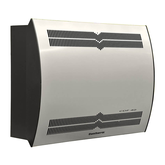
Product description: Overall description Product description Overall description Air flow direction This illustrates the functional principle of the CDF 40-50-70. Fig. 1 Functionality of CDF 40-50-70 work in accordance with the condensation principle. the dehumidifier Humid air from the room is drawn into the unit by one or two fans. - Page 7 Product description: Overall description Two cable grooves for accessory make it Cable groove easy to guide the cables from the control (accessory) panel to the mains electricity connection and out of the unit. Groove B is for use with cable from ex- ternal RH sensor as it requires a seperate groove to avoid interference.
- Page 8 Product description: Overall description Pos . Part Illustration Presentation LED lamp Air outlet Air inlet Drip tray Control panel (behind the cover) Cable groove (for accessory only) Humidity sensor Wall mounting spacers (incl. in delivery) Mains electricity connection (behind the lid) Wall bracket Water drain Bottom view...
-
Page 9: Enclosure Dimensions
Product description: Enclosure dimensions Enclosure dimensions CDF 40-50-70 CDF40 1010 CDF50 1160 CDF70 1495 CDF 40-50-70 Fig. 3... -
Page 10: Technical Data
Product description: Technical data Technical data Data sheet Specification unit CDF 40 CDF 50 CDF 70 Operating range, 40-100 40-100 40-100 humidity Operating range, temperature °C 3-23 3-23 3-23 Air volume at max. external pressure m3/h Capacity at 20ºC - RH 60 l/day SEC 20ºC - RH 60... -
Page 11: Installation
• Doors and windows must be kept closed when the dehumidifier is in function. • To make sure that the room air passes freely through the dehumidifier, air inlet and air NOTICE outlet openings must be free. Mounting Please follow this procedure to mount the CDF 40-50-70: CDF 40-50-70 Step Description Illustration... - Page 12 Installation: Wall mounting Fix the wall suspension bar sup- plied with the unit to the wall. NB: It is important to fix it horizontally to ensure correct condensate outlet. Fasten the two wall mounting spacers (included in the deliv- ery) on the back of the unit. Drain outlet: Connect a drain hose and make a condensate outlet through...
- Page 13 Installation: Wall mounting Hang the dehumidifier on the wall suspension bar.
-
Page 14: Electrical Connection
Installation: Electrical connection Electrical connection Risk of damaging the dehumidifier, if it has been lying down . Warning CAUTION The compressor can be damaged permanently, when the unit is started up just after it has been lying down. Caution • Wait 1 hour with the start up of the dehumidifier, if the unit has been lying down (e.g. - Page 15 12 VDC Connection of LPHW (water) or electric heating helps controlling the Heat control indoor temperature. Contact your Dantherm dealer for more informa- tion. External RH/T There is an option for connecting an external RH/T sensor, which makes it possible to overrule sensor connection the internal sensors.
- Page 16 Installation: Electrical connection Alarm There is an option for connecting an external alarm, which makes it possible to see, when the Run/ fail dehumidifier is operating normally or has an error. In order to use this option you must create connection your own external electrical circuit and connect it to the run/fail terminal on the main PCB (Optional)
-
Page 17: Operation
Operation: Control panel Operation Control panel Risk of electric shock Warning DANGER An electric shock can cause severe burning and in most extreme cases shock to the brain, strain to the heart, injury to other organs or result in death. Caution •... - Page 18 Operation: Control panel Menu overview Default view Example < rH50 > < > < EFOF > < SIOF > Update to latest software version, if the menu looks different. Menu description Code Function Default Value Description value range Relative 40-99 The unit will start dehumidifying, when the sen- humidity (%) sor measures a relative humidity higher than the set value.
-
Page 19: Maintenance And Care
Insert filter in the filter holder, reattach the cap and lock the two locks. (From Step 1) NB: If the filter (one size PPI filter with order no. 094686) has to be replaced, you can order it through a Dantherm dealer. Annual service The dehumidifier should be inspected once a year. -
Page 20: Software Update And Log Files
Maintenance and care: Software update and log files Software update and log files Access data log/ If you wish to read the log file from the unit without updating the software follow these steps. Step Action Insert an empty FAT32 USB memory stick (see section “Formatting to FAT32” on page 21). - Page 21 Follow these steps in order to update the software version. Step Action Use an empty USB memory stick. Obtain latest software version from Dantherm and copy the file to the USB memory stick. Insert the USB memory stick in the USB port of the control panel of the unit.
-
Page 22: Trouble Shooting
Maintenance and care: Trouble shooting Trouble shooting Display messages The CDF can display a number of Information and Error Messages to help finding a fault. Every single message and associated problems are explained in the following sections. Information Display Description messages Abrh The relative humidity is out of range. - Page 23 Sensor fail - Defective sensor Replace sensor every 5 min. check display If you cannot find the reason for the fault, switch off the unit immediately in order to prevent further damage. Contact a service technician or a Dantherm representative.
-
Page 24: Spare Parts
Maintenance and care: Spare parts Spare parts Introduction Spare parts for the CDF unit shown in this section, are available via Dantherm dealers. Fig. 7 Pos . Description CDF 40 CDF 50 CDF 70 Wall bracket 094696 094827 094828 Wall mounting spacers... -
Page 25: Schematics
Schematics: Cooling circuit Schematics Cooling circuit Illustration This illustration shows the cooling circuit of the CDF range. Fig. 8 Description This table lists the different parts of the cooling circuit according to Fig. 8. Pos . Description Compressor Evaporator Air-cooled condenser Thermostatic expansion valve Receiver/liquid line drier Solenoid valve for pressure equalization... -
Page 26: Main Pcb
Schematics: Main PCB Main PCB Illustration This illustration shows the main PCB and its terminals. Fig. 9... -
Page 27: Wiring Diagram
Schematics: Wiring diagram Wiring diagram Illustration This illustration shows the standard connection of the unit. Resistance coversion Temp. °C Kohm TEMP. 6,96 SENSOR 5,44 (EVAPO.) 4,29 3,40 2,72 2,19 1,77 TEMP. J1 (DIODE) LED LAMP J17 (TEMP.) SENSOR RGB RE EVAP.1 (COND.) RGB GR... - Page 32 Marienlystvej 65 7800 Skive Denmark support.dantherm.com Dantherm can accept no responsibility for possible errors and changes (en) Der tages forbehold for trykfejl og ændringer (da) Irrtümer und Änderungen vorbehalten (de) Dantherm n’assume aucune responsabilité pour erreurs et modifications éventuelles (fr)
Need help?
Do you have a question about the CDF 40 and is the answer not in the manual?
Questions and answers