Table of Contents
Advertisement
Quick Links
MASTERFLEX
REGLO MFLX78018-10
®
MASTERFLEX
REGLO MFLX78018-40
®
(US & Canada only) Toll Free 1-800-MASTERFLEX • 1-800-637-3739
(Outside US & Canada) 1-847-381-7050
masterflex.tech @ avantorsciences.com | www.avantorsciences.com/masterflex
OPERATING MANUAL:
REGLO DIGITAL PUMP
DRIVES WITH ADVANCED
CONNECTIVITY
Model Nos.
MFLX78018-10
MFLX78018-12
MFLX78018-14
MFLX78018-20
MFLX78018-22
MFLX78018-24
MFLX78018-40
MFLX78018-42
A-1299-5201
Edition 04
Advertisement
Table of Contents

Related Manuals for Ismatec MASTERFLEX MFLX78018-10


Summary of Contents for Ismatec MASTERFLEX MFLX78018-10
- Page 1 OPERATING MANUAL: REGLO DIGITAL PUMP DRIVES WITH ADVANCED CONNECTIVITY Model Nos. MFLX78018-10 MFLX78018-12 MFLX78018-14 MFLX78018-20 MASTERFLEX REGLO MFLX78018-10 MFLX78018-22 ® MFLX78018-24 MFLX78018-40 MFLX78018-42 MASTERFLEX REGLO MFLX78018-40 ® A-1299-5201 Edition 04 (US & Canada only) Toll Free 1-800-MASTERFLEX • 1-800-637-3739 (Outside US & Canada) 1-847-381-7050 masterflex.tech @ avantorsciences.com | www.avantorsciences.com/masterflex...
- Page 2 © 2023 Masterfl ex LLC. All rights reserved. Masterfl ex® is a registered trademark of the Masterfl ex LL C. Trademarks bearing the ® symbol in this publication are registered in the US and in other countries. PUMP FOR LIQUIDS ORIGINAL INSTRUCTIONS Masterflex Masterflex REGLO Digital Pump Drive with Advanced Connectivity...
-
Page 3: Table Of Contents
Table of Contents Table of Contents SECTION 1: INTRODUCTION Safe Operation About the REGLO Package Contents Peristaltic Cassette Models Peristaltic Minifl ex Models Non-Peristaltic Pump Models Available Models SECTION 2: BASIC SETUP & SETTINGS Touchscreen Icons Before Starting the Drive Switching on the Drive Settings Language Settings... - Page 4 Table of Contents Time Mode Run Screen 3-20 Time Mode Edit Screen 3-21 Time Mode Operation 3-21 Saving Time Mode Settings as a New Program 3-23 Volume Mode 3-24 Volume Mode Run Screen 3-24 Volume Mode Edit Screen 3-25 Volume Dispense Mode Operation 3-25 Saving Volume Mode Settings as a New Program 3-27...
- Page 5 Table of Contents Product Return 5-10 Warranty 5-10 Disposal 5-10 Masterflex Masterflex REGLO Digital Pump Drive with Advanced Connectivity...
-
Page 6: Section 1: Introduction
Section 1: Introduction SECTION 1: INTRODUCTION SAFE OPERATION Th e REGLO Digital Pump Drive with Advanced Connectivity is designed for pumping and dispensing applications in laboratory and process environments. Confi rm that the pump drive is operated only in the manner specifi ed in this operating manual and that safe work practices and Good Laboratory Practice (GLP) are followed. -
Page 7: About The Reglo
Section 1: Introduction ABOUT THE REGLO Th e REGLO Digital Pump Drive with Advanced Connectivity off ers precise fl ow control and highly accurate fl uid dispensing ideal for laboratory, process, and fi eld use. All REGLO precision drives include a highly accurate, maintenance-free motor and an easy to navigate touchscreen that makes setup and operation easier than ever. -
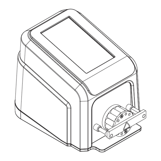
Page 8: Peristaltic Miniflex Models
Section 1: Introduction Peristaltic Miniflex Models Th e REGLO is available in two non-cassette pump head models (78018-40 and 78018-42). Th e REGLO Minifl ex Digital Pump Drives feature: • An easy to load pump head that accepts continuous lengths of tubing for clean fl ow paths. •... -
Page 9: Section 2: Basic Setup & Settings
Section 2: Basic Setup & Settings SECTION 2: BASIC SETUP & SETTINGS Touchscreen Pump Head Handle Pump Head Miniflex Models Touchscreen Roller-Head Cassette Cassette Models DB-25 Port Power Switch Power Cable Locking Barrel Connector Ethernet Port USB Port Masterflex Masterflex REGLO Digital Pump Drive with Advanced Connectivity... -
Page 10: Touchscreen Icons
Section 2: Basic Setup & Settings TOUCHSCREEN ICONS Analog Input Mode New User Calibrate Pause Calibration Complete Prime Clockwise Program Close/Cancel Ramp Down Confirm Ramp Up Connectivity Status Record Volume Continuous Mode Reset Counterclockwise Screen Lock Delete Settings Display Brightness Start Edit Stop... -
Page 11: Before Starting The Drive
Section 2: Basic Setup & Settings BEFORE STARTING THE DRIVE CAUTION: Do not block the rear panel of the pump drive. Th e power switch must always be easy to access and the power cord must always be easy to disconnect. CAUTION: Turn the drive off before removing or installing tubing. -
Page 12: Settings
Section 2: Basic Setup & Settings SETTINGS Th e Settings Screen allows access to basic confi guration settings. Th e Settings Screen is accessed by tapping SETTINGS from any of the mode screens. NOTE: If User Management is enabled only users with authorization can access the Settings Screen (for further information see "User Management"... -
Page 13: Setting The Date
Section 2: Basic Setup & Settings Setting the Date To change the date: 1. Tap SETTINGS from any of the mode screens. Th e Settings Screen will be displayed. 2. Tap DATE. 3. Select the desired date format (either month/day/year or day/month/year). 4. -
Page 14: Device Information
Section 2: Basic Setup & Settings Device Information Th e Device Information Screen provides pump drive details such as MAC address, IP address, software version, build date, and fi rmware version. Factory reset and updates are also accessed from the Device Information Screen. -
Page 15: Wi-Fi Settings
Section 2: Basic Setup & Settings WI-FI Settings Th e REGLO can connect to a network using Wi-Fi and Ethernet connections. NOTE: • Th e Ethernet connection will take priority if both Wi-Fi and Ethernet are used simultaneously. • Th e REGLO supports WEP, WPA, WPA2, and None (open) Wi-Fi security protocols. To select a Wi-Fi network: 1. -
Page 16: User Management
Section 2: Basic Setup & Settings User Management Th e REGLO allows user access to be controlled using confi gurable permission levels. Default permissions: • USER: Able to use basic pump drive functions and run programs. • SUPER USER: Same level of access as USER but with the ability to create and modify programs. •... -
Page 17: Auto Start
Section 2: Basic Setup & Settings Deleting a user: NOTE: Th ere must always be at least one ADMIN user. ADMIN users cannot delete their own user profi le. 1. Tap SETTINGS from any of the mode screens. Th e Settings Screen will be displayed. 2. -
Page 18: Loading Tubing
Section 2: Basic Setup & Settings LOADING TUBING Cassette Models CAUTION: Turn the drive off before removing or installing tubing. Fingers or loose clothing could get caught in the drive mechanism. Th e REGLO Cassette models use MS/CA Click’n’go cassettes for easy loading and removal, and to allow for tubes with diff erent diameters and materials to be used on the same roller-head. - Page 19 Section 2: Basic Setup & Settings To condition new tubing: After installing new tubing the pump should be run for 20-30 minutes at full rpm (160 rpm). Th is is recommended to properly condition new tubing and to increase dispense accuracy. If required, the pump can be run dry while conditioning.
-
Page 20: Miniflex Models
Section 2: Basic Setup & Settings Miniflex Models CAUTION: Turn the drive off before removing or installing tubing. Fingers or loose clothing could get caught in the drive mechanism. • Check to ensure that the rollers are clean and free of defects. •... - Page 21 Section 2: Basic Setup & Settings To condition new Minifl ex tubing: After installing new tubing the pump should be run for 20-30 minutes at full rpm (350 rpm). Th is is recommended to properly condition new tubing and to increase dispense accuracy. If required, the pump can be run dry while conditioning.
-
Page 22: Priming The Pump Drive
Section 2: Basic Setup & Settings PRIMING THE PUMP DRIVE It is recommended that you prime the pump drive before use. Priming the pump draws fl uid through the tubing and eliminates air pockets from the system. CAUTION: Turn the drive off before removing or installing tubing. Fingers or loose clothing could get caught in the drive mechanism. -
Page 23: Tube Calibration
Section 2: Basic Setup & Settings TUBE CALIBRATION To ensure accurate dispensing of fl uids, tube calibration should be performed whenever fl uids, fl ow rate or tubing is changed. Tube calibration can be accessed from the Continuous Mode Run Screen or from either of the Volume or Time Mode Edit screens. - Page 24 Section 2: Basic Setup & Settings 7. Press and hold PRIME to prime the pump. Priming will stop when PRIME is released. 8. Tap SIZE from the Continuous Mode Screen or tap EDIT and then SIZE if either the Volume or Time Mode Screen is displayed.
-
Page 25: Section 3: Operation
Section 3: Operation SECTION 3: OPERATION WARNING: Tube breakage may result in fl uid being sprayed from the pump. Use appropriate measures to protect operator and equipment. CAUTION: Keep fi ngers away from the rotor while the pump is in operation. Stop the pump before loading or unloading tubing. -
Page 26: Continuous Mode
Section 3: Operation CONTINUOUS MODE In Continuous Mode the pump will operate at a selected rpm and/or fl ow rate until stopped by the user. Continuous Mode Run Screen Th e Continuous Mode Run Screen is accessed by selecting CONTINUOUS from the Mode Selection Screen. -
Page 27: Continuous Mode Operation
Section 3: Operation hold UNLOCKED until the icon changes to LOCKED and a red border appears around the screen. To unlock the screen: Press and hold LOCKED until the icon changes to UNLOCKED J. LOGOUT: Tap to log out a user. NOTE: Th is option is only available if User Management is enabled in Settings (for further information see "User Management"... -
Page 28: Saving Continuous Mode Settings As A New Program
Section 3: Operation Saving Continuous Mode Settings as a New Program Changes made to mode parameters can be saved as a new program for easier access to frequently used settings. NOTE: If User Management is enabled only users with authorization can create and modify programs (for further information see "User Management"... -
Page 29: Time Mode
Section 3: Operation TIME MODE In Time Mode the pump will operate at a selected rpm and/or fl ow rate for a selected time and/or batch total. At the completion of the selected time or batch total the pump will automatically stop. Time Mode Run Screen Th e Time Mode Run Screen is accessed by selecting TIME from the Mode Selection Screen. -
Page 30: Time Mode Edit Screen
Section 3: Operation L. FLOW DIRECTION: Tap DIRECTION to select either clockwise or counterclockwise fl ow direction. M. SCREEN LOCK: Locking the screen disables all touchscreen functions. To lock the screen: Press and hold UNLOCKED until the icon changes to LOCKED and a red border appears around the screen. - Page 31 Section 3: Operation To operate the pump in Time Mode: 1. Tap TIME from the Mode Selection Screen. Th e Time Mode Run Screen will be displayed. 2. Tap EDIT to access the Time Mode Edit Screen. 3. Tap ON TIME to set the amount of time for each pump operation. Th e On Time Edit Screen will be displayed.
-
Page 32: Saving Time Mode Settings As A New Program
Section 3: Operation Saving Time Mode Settings as a New Program Changes made to mode parameters can be saved as a new program for easier access to frequently used settings. NOTE: If User Management is enabled only users with authorization can create and modify programs (for further information see "User Management"... -
Page 33: Volume Mode
Section 3: Operation VOLUME MODE In Volume Mode the pump will operate at a selected rpm and/or fl ow rate until a selected volume of fl uid has been pumped. When the selected volume has been pumped the drive will automatically stop. Volume Mode Run Screen Th e Volume Mode Run Screen is accessed by selecting VOLUME from the Mode Selection Screen. -
Page 34: Volume Mode Edit Screen
Section 3: Operation K. START/STOP/PAUSE: During operation, the display will change from START to PAUSE STOP/ RESET L. FLOW DIRECTION: Tap DIRECTION to select either clockwise or counterclockwise fl ow direction. M. SCREEN LOCK: Locking the screen disables all touchscreen functions. To lock the screen: Press and hold UNLOCKED until the icon changes to LOCKED and a red border appears around the... - Page 35 Section 3: Operation To operate the pump in Volume Mode: 1. Tap VOLUME from the Mode Selection Screen. Th e Volume Mode Run Screen will be displayed. 2. Tap EDIT to access the Volume Mode Edit Screen. 3. Tap VOLUME. Th e Dispense Volume Screen will be displayed. a.
-
Page 36: Saving Volume Mode Settings As A New Program
Section 3: Operation b. If enabled, enter the desired degrees of reverse rotation using the onscreen keypad. NOTE: Typical values range from 5 to 45 degrees. c. Tap CONFIRM to save or CANCEL to discard changes and return to the Volume Mode Edit Screen. -
Page 37: Volume Record
Section 3: Operation 2. Tap EDIT 3. Tap ANTI-DRIP. Th e Anti-Drip Screen will be displayed. 4. Tap ON or OFF to enable or disable ANTI-DRIP. 5. If enabled, enter the desired degrees of reverse rotation using the onscreen keypad. NOTE: Typical values range from 5 to 45 degrees. -
Page 38: Analog Input Mode
Section 3: Operation ANALOG INPUT MODE CAUTION: Power must be turned off before connecting the external analog control cable to prevent damage to the drive. Th e REGLO Digital Pump Drive can be controlled and monitored through the pump drive’s DB-25 female connection port. -
Page 39: Analog Input
Section 3: Operation F. LOGOUT: Tap to log out a user. NOTE: Th is option is only available if User Management is enabled in Settings (for further information see "User Management" on page 3-7). Analog Input CAUTION: Power must be turned off before connecting the external analog control cable to pre- vent damage to the drive. -
Page 40: Saving Analog Input Mode Settings As A New Program
Section 3: Operation Saving Analog Input Mode Settings as a New Program Changes made to mode parameters can be saved as a new program for easier access to frequently used mode settings. NOTE: If User Management is enabled only users with authorization can create and modify programs (for further information see "User Management"... -
Page 41: Masterflexlive
Section 3: Operation MASTERFLEXLIVE™ Th e REGLO Digital Pump Drive can be monitored through the Masterfl exLive™ website using an Ethernet or Wi-Fi connection. Masterfl exLive™ can be accessed from any suitable digital device connected to the internet, such as a laptop, tablet, smartphone or desktop computer. See www.masterfl ex.com for more information. - Page 42 Section 3: Operation To add a new Time Mode program: 1. Tap NEW PROGRAM from the Mode Selection Screen. Th e New Program Screen will be displayed. NOTE: If NEW PROGRAM is not displayed on the Mode Selection Screen tap SCROLL to view additional pages.
-
Page 43: Adding A New Program: Volume Mode
Section 3: Operation • If there are multiple programs tapping SCROLL will display additional pages. Adding a New Program: Volume Mode To add a new Volume Mode program: 1. Tap NEW PROGRAM from the Mode Selection Screen. Th e New Program Screen will be displayed. NOTE: If NEW PROGRAM is not displayed on the Mode Selection Screen tap SCROLL to view additional pages. -
Page 44: Adding A New Program: Analog Input Mode
Section 3: Operation a. Enter the desired number of dispenses in a batch using the onscreen keypad. NOTE: If required, tap INFINITE ∞ to select an infi nite number of dispense cycles. If infi nite is selected, the pump will run continuously. -
Page 45: Using Program Modes
Section 3: Operation NOTE: • Once saved, new programs are added in alphabetical order to the bottom of the Mode Selection Screen. • If there are multiple programs tapping SCROLL will display additional pages. Using Program Modes Custom programs will appear in alphabetical order at the bottom of the Mode Selection Screen. If there are multiple programs tapping SCROLL will display additional pages. -
Page 46: Deleting A Program
Section 3: Operation • "Adding a New Program: Analog Input Mode" on page 3-35. • NOTE: Once the individual mode settings have been edited and saved the Program Edit Screen will be displayed. 3. Tap CONFIRM to save or CANCEL to discard changes and return to the Mode Selection Screen. -
Page 47: Section 4: Communication Specification
Section 4: Communication Specification SECTION 4: COMMUNICATION SPECIFICATION ETHERNET/IP MODE In Ethernet/IP mode, the pump can be operated in Continuous, Volume and Time modes. Th e pump drives are equipped with Ethernet/IP for real time control via a PLC. Th e .EDS command fi le is avialable for down- load on the ODVA website: https://marketplace.odva.org/products/1923-masterfl ex?lang=en Ethernet/IP Setup... - Page 48 Section 4: Communication Specification In the device menu, enable the Ethernet/IP feature by toggling to select ON. Once enable, the following message appears on the UI. Press Accept on this screen. Masterflex Masterflex REGLO Digital Pump Drive with Advanced Connectivity...
- Page 49 Section 4: Communication Specification Once the Ethernet/IP has been confi gured and enabled, you will now be able to view the pump from your PLC. To enable remote control, you must confi gure the pump from your PLC using the bit "Pump1:O.Toggle_Remote_Local_Control_1_to_0".
-
Page 50: Masterflex Ethernet/Ip
Section 4: Communication Specification MASTERFLEX ETHERNET/IP Input data; 56 bytes of input data from pump to master. Bytes Data Type Description 32-Bit INT Pump Status Bit 0: Status OK Bit 1: Pump Running Bit 2: Dispense Running Bit 3: Tube Uncalibrated Bit 4: Head Open Bit 5: Reserved Bit 6: Flow Direction CCW... - Page 51 Section 4: Communication Specification Output data; 28 bytes of output data from master to pump. Bytes Data Type Description BYTE Pump Control Bit 0: Run/Pause (1 = RUN; 0 = PAUSE) Bit 1: Stop and Reset Dispense (1 to 0 transition) Bit 2: Toggle Remote/Local Control (1 to 0 transition) Bit 3: Clear Cumulative Volume (1 to 0 transition) Bit 4: Reserved...
-
Page 52: Section 5: Service & Maintenance
Section 5: Service & Maintenance SECTION 5: SERVICE & MAINTENANCE CAUTION: Replace the power cord only with one of the same type and rating. CAUTION: Unplug the pump drive’s power cable from the mains power outlet when cleaning or performing maintenance on the drive. FIRMWARE UPDATES If the REGLO is connected to the internet, updates can be downloaded directly onto the pump drive. -
Page 53: Cleaning The Pump Drive
Section 5: Service & Maintenance CLEANING THE PUMP DRIVE CAUTION: Unplug the pump drive’s power cable from the mains power outlet when cleaning or performing maintenance on the drive. If required, the pump drive may be wiped clean using a soft cloth lightly moistened with either isopropyl or ethyl alcohol. -
Page 54: Color-Coded Three-Stop Tubing
Section 5: Service & Maintenance Color-Coded Three-Stop Tubing Color-Coded Th ree-Stop Tubing suitable for use with cassettes: Color-Coded Stops MM ID ORANGE/BLACK/ORANGE 0.13 ORANGE/RED/ORANGE 0.19 ORANGE/BLUE/ORANGE 0.25 WHITE/BLUE/WHITE 0.28 RED/BLUE/RED 0.31 BROWN/BLUE/BROWN 0.33 BROWN/BLACK/BROWN 0.36 ORANGE/GREEN/ORANGE 0.38 GREEN/YELLOW/GREEN 0.44 ORANGE/YELLOW/ORANGE 0.51 WHITE/YELLOW/WHITE 0.57... -
Page 55: Miniflex Pump Head Replacement
Section 5: Service & Maintenance MINIFLEX PUMP HEAD REPLACEMENT If necessary, the Minifl ex pump head can be replaced. Contact Technical Assistance (see "Technical Assistance" on page 5-10) to order the appropriate replacement pump head. Description: Part Number Replacement Miniflex Single Channel Pump Head 77220-20 Replacement Miniflex Dual Channel Pump Head 77220-30... -
Page 56: Db-25 Electrical Connections
Section 5: Service & Maintenance DB-25 ELECTRICAL CONNECTIONS CAUTION: Power must be turned off before connecting the external analog control cable to prevent damage to the drive. Contact Arrangements: Pin No. Description Pin No. Description DB-25 DB-25 Speed Control Voltage Input (0–10 V) Speed Signal Voltage Output (0–10 V) Speed Control Current Input (0–20 mA) Start/Stop Input... -
Page 57: Troubleshooting
Section 5: Service & Maintenance TROUBLESHOOTING For further assistance, or for issues that cannot be resolved, see "Technical Assistance" on page 5-10. Symptom Cause Remedy Motor does not rotate. No power. 1. Check that the power cord is securely plugged into the drive. Display does not light. -
Page 58: Error Definitions
Section 5: Service & Maintenance ERROR DEFINITIONS Error #2: No Encoder Pulses Description: The drive's processor has not received expected encoder feedback. Actions: Drive will stop immediately. Verify load is correct and power cycle drive. If error persists see "Technical Assistance"... -
Page 59: Specifications
Section 5: Service & Maintenance SPECIFICATIONS OUTPUT Speed: 160 RPM Models 0.15 to 160 RPM 350 RPM Models 0.18 to 350 RPM Torque Output, All Models 90 oz-in Max Continuous: Speed Regulation: All Models Line ±0.1% F.S. Load ±0.1% F.S. Drift ±0.1% F.S. - Page 60 Section 5: Service & Maintenance CONSTRUCTION Dimensions (L x W x Drive Only 7.62” x 5.75” x 6.31” (194 mm x 146 mm x 160 mm) Weight: Drive Only 5.74 lbs. (2.60 kg) Enclosure Rating: All Models IP31 per IEC 60529 ENVIRONMENT Operating Temperature: All Models...
-
Page 61: Technical Assistance
Section 5: Service & Maintenance TECHNICAL ASSISTANCE If you have any questions about the use of this product contact the manufacturer or authorized seller. PRODUCT RETURN Like all pumps, the REGLO pump drive contains components that will wear over a period of time. To limit charges and delays contact the seller or manufacturer for authorization and shipping instructions before returning the product, either within or outside of the warranty period. - Page 62 US & Canada only *EN809 manufactured by: Toll Free 1-800-MASTERFLEX | 1-800-637-3739 Masterflex LLC 28W092 Commercial Avenue, Barrington, IL 60010 Outside US & Canada masterflex.tech @ avantorsciences.com 1-847-381-7050 www.avantorsciences.com/masterflex...
Need help?
Do you have a question about the MASTERFLEX MFLX78018-10 and is the answer not in the manual?
Questions and answers