Advertisement
Quick Links
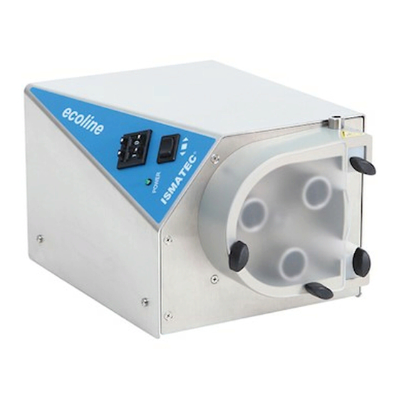
Betriebsanleitung für Pumpenkopf 380 AD
(zu den Antrieben MCP oder BVP)
Technische Daten
Prinzip:
1-Kanal Schlauchpumpe, kugelgelagert
3 Pumprollen aus Edelstahl
für verschiedene Schlauchtypen einstellbar
Fließrate:
0.41– 3600 ml/min
mit Schlauchwandstärke 1.6 mm
3.4 – 1500 ml/min
mit Schlauchwandstärke 2.4 mm
Druck:
max. 2.5 bar mit Schläuchen bis 8 mm iØ
1.5 bar mit größeren Schläuchen
Standardschläuche (Meterware)
WS 1.6 mm iØ 1.6 – 11.1 mm
WS 2.4 mm iØ 4.8 + 6.4 mm, (WS = Wandstärke)
3
WS-Graduationsmarken
Graduation for TW
1.0
mm
1.5
mm
1.6
mm
2.0
mm
2.4
mm
1
) WS = Wandstsärke
WT = wall thickness
Anpressdruck der Pumprollen einstellen
Der Rändelring (4) mit den 5 Markie rungen ermöglicht es, den
korrekten Anpressdruck der Rollen auf den Schlauch wie folgt
einzustellen:
– Öffnen Sie die Abdeckhaube (1)
– Lösen Sie die Arretierung des Sterngriffes (7)
➜ nach links drehen
– Drehen Sie den Rändelring (4) so, dass die gewünschte Mar-
kierung (je nach Wandstärke, siehe Abbildung nächste Seite)
auf die Kerbe im dreiecksförmigen Rollenkopf (3) ausgerich-
tet ist
– Durch gleichzeitiges Festziehen des Sterngrif fes (7) arretieren
Sie die Pumprollen in der gewünschten Position
Der besondere Vorteil dieser Einstellmöglichkeit liegt darin, dass
der Anpressdruck konzentrisch von der Rollenkopfachse zur
Kontur des Schlauchbettes erfolgt. Dies garantiert einen regel-
mäßigen und gleich bleibenden Anpress druck, unabhängig von
der Stellung des Rollen kopfes und der Wandstärke des Schlau-
ches. Diese Gegebenheit wirkt sich sehr günstig auf die Pump-
charakteristik und Schlauchlebens dauer aus.
1
2
3
1
)
1
)
ISMATEC SA Labortechnik-Analytik
A Unit of IDEX-Corporation
Feldeggstrasse 6
ISO 9001 certifi ed
8152 Glattbrugg ZH, Switzerland
Operating manual for pumphead 380 AD
(for the drives MCP oder BVP)
Technical specifi cations
Principle:
Flow-rate:
Pressure:
Standard tubing:
WT 1.6 mm ID1.6 – 11.1 mm
WT 2.4 mm ID 4.8 + 6.4 mm, (WT = wall thickness)
4
5
a
6
a
7
6
b
8
5
b
Adjusting the roller pressure
The knurled ring (4) with the 5 graduation marks allows you to
adjust the pressure of the rollers onto the tubing as follows:
– Open pumphead cover (1)
– Loosen the star grip (7)
➜ turn in the counter-clockwise direction
– Turn the knurled ring (4) so that the correct graduation mark
(depends on the wall thickness, see fi gure below) is aligned
with the notch in the triangular roller-head (3)
– By simultaneous fastening the star grip (7) you lock the
pump-rollers in the position required
The particular advantage of this roller adjustment is that the
contact pressure of the 3 rollers occurs concentrically from the
roller-head shaft to the contour of the tube-bed. This ensures a
regular and constant pressure, independently of the position of
the roller-head and the wall thickness of the tubing used. This
provides a favorable effect on the pump characteristics and the
service-life of the tubing.
1-channel tubing pump, with ball bearings
3 stainless steel rollers
adjustable for different tubing types
0.41– 3600 ml/min
with 1.6 mm tubing wall thickness
3.4 – 1500 ml/min
with 2.4 mm tubing wall thickness
max. 2.5 bar (36 psi) with tubing up to
8 mm ID, 1.5 bar (22psi) with larger tubing
T
y
p
T /
y
p
e
K
a
n
a
/ l
C
h
a
n
n
l e
P
u
m
p
e
n
o r
e l l
/ n
R
o
e l l
S
h c
a l
c u
t h
p y
/
T
u
b
n i
g
m
n i
–
1
p r
m
/ t
m
n i
S
h c
a l
u
h c
i
/ Ø
W
S
T
u
b
n i
g
I
D .
/ .
W
T
T
p y
. I
. D
W
y T
e p
m
m
m
B
1
6 .
C
3
2 .
D
4
8 .
E
6
4 .
F
8
0 .
M
9
5 .
N
1
1
1 .
G
4
8 .
H
6
4 .
Tel.
41 (0)44 874 94 94
+
Fax
41 (0)44 810 52 92
+
sales.ismatec@idexcorp.com
www.ismatec.com
3
8
0
A
D
1
s r
3
M
t e
r e
w
a
e r
S
a t
n
d
a
d r
T
u
b
n i
g
1
2
4
0
F
e i l
ß
a r
e t
n
/
F
o l
w
r
t a
s e
m
/ l
m
n i
T
m
n i
m
x a
m
1
6 .
0
4 .
1
9
9
1
6 .
1
5 .
3
7
0
1
6 .
3
4 .
8
3
0
1
6 .
6
2 .
1
5
0
0
1
6 .
9
5 .
2
3
0
0
1
6 .
1
3
3
0
0
0
1
6 .
1
5
3
6
0
0
2
4 .
3
5 .
8
3
0
2
4 .
6
2 .
1
5
0
0
Advertisement

Related Manuals for Ismatec 380 AD


Summary of Contents for Ismatec 380 AD
- Page 1 Betriebsanleitung für Pumpenkopf 380 AD Operating manual for pumphead 380 AD (zu den Antrieben MCP oder BVP) (for the drives MCP oder BVP) Technische Daten Technical specifi cations Prinzip: 1-Kanal Schlauchpumpe, kugelgelagert Principle: 1-channel tubing pump, with ball bearings 3 Pumprollen aus Edelstahl 3 stainless steel rollers für verschiedene Schlauchtypen einstellbar...
- Page 2 Betriebsanleitung für Pumpenkopf 380 AD Operating manual for pumphead 380 AD (zu den Antrieben MCP oder BVP) (for the drives MCP oder BVP) Schlauch einlegen Loading the tubing Öffnen Sie die Abdeckhaube (1) Open the pumphead cover (1) Montieren Sie den Pumpenschlauch wie folgt: Load the pump tubing as follows: –...
Need help?
Do you have a question about the 380 AD and is the answer not in the manual?
Questions and answers