YASKAWA Varispeed G7 Series Instruction Manual
General purpose inverter (advanced vector control)
Hide thumbs
Also See for Varispeed G7 Series:
- Instruction manual (499 pages) ,
- Technical manual (456 pages)
Table of Contents
Advertisement
General Purpose Inverter (Advanced Vector Control)
Varispeed G7
Instruction Manual
Model: CIMR-G7A
200 V Class 0.4 to 110 kW (1.2 to 160 kVA)
400 V Class 0.4 to 300 kW (1.4 to 460 kVA)
To properly use the product, read this manual thoroughly and retain
for easy reference, inspection, and maintenance. Ensure the end user
receives this manual.
MANUAL NO. TOE-S616-60.1F
Advertisement
Table of Contents
Troubleshooting

Related Manuals for YASKAWA Varispeed G7 Series


Summary of Contents for YASKAWA Varispeed G7 Series
- Page 1 General Purpose Inverter (Advanced Vector Control) Varispeed G7 Instruction Manual Model: CIMR-G7A 200 V Class 0.4 to 110 kW (1.2 to 160 kVA) 400 V Class 0.4 to 300 kW (1.4 to 460 kVA) To properly use the product, read this manual thoroughly and retain for easy reference, inspection, and maintenance.
- Page 2 • When ordering a new copy of the manual due to damage or loss, contact your Yaskawa represen- tatives or the nearest Yaskawa sales office and provide the manual number shown on the front cover.
-
Page 3: Safety Information
Safety Information The following conventions are used to indicate precautions in this manual. Failure to heed pre- cautions provided in this manual can result in serious or possibly even fatal injury or damage to the products or to related equipment and systems. Indicates precautions that, if not heeded, could possibly result in loss of life or serious injury. -
Page 4: Safety Precautions
Safety Precautions Confirmations upon Delivery CAUTION • Never install an Inverter that is damaged or missing components. Doing so can result in injury. Installation CAUTION • Always hold the case when carrying the Inverter. If the Inverter is held by the front cover, the main body of the Inverter may fall, possibly resulting in injury. •... - Page 5 CAUTION • Tighten all terminal screws to the specified tightening torque. Otherwise, a fire may occur. • Do not connect AC power to output terminals U, V, and W. The interior parts of the Inverter will be damaged if voltage is applied to the output terminals. •...
- Page 6 WARNING • Reset alarms only after confirming that the RUN signal is OFF. Injury may occur. CAUTION • Don't touch the radiation fins (heatsink), braking resistor, or Braking Resistor Unit. These can become very hot. Otherwise, a burn injury may occur. •...
- Page 7 CAUTION • A CMOS IC is used in the control board. Handle the control board and CMOS IC carefully. The CMOS IC can be destroyed by static electricity if touched directly. • Do not change the wiring, or remove connectors or the Digital Operator, during operation. Doing so can result in personal injury.
-
Page 8: Warning Information And Position
Warning Information and Position There is warning information on the Inverter in the position shown in the following illustration. Always heed the warnings. Warning information Warning position information position Illustration shows the CIMR-G7A2018 Illustration shows the CIMR-G7A20P4 Warning Information WARNING Risk of electric shock. -
Page 9: Warranty Information
Periodic inspections must be conducted by the customer. However, upon request, Yaskawa or one of Yaskawa’s Service Centers can inspect the product for a fee. In this case, if after confer- ring with the customer, a Yaskawa product is found to be defective due to Yaskawa workman- ship or materials and the defect occurs during the warranty period, then this fee will be waived and the problem remedied free of charge. -
Page 10: Registered Trademarks
Registered Trademarks The following registered trademarks are used in this manual. DeviceNet is a registered trademark of the ODVA (Open DeviceNet Vendors Association, • Inc.). InterBus is a registered trademark of Phoenix Contact Co. • ControlNet is a registered trademark of ControlNet International, Ltd. •... -
Page 11: Table Of Contents
Contents Safety Information ....................ii Safety Precautions ..................iii Warning Information and Position ..............vii Warranty Information..................viii Registered Trademarks...................ix Before Reading This Manual................ix Handling Inverters ..............1-1 Varispeed G7 Introduction................1-2 Varispeed G7 Models ..................... 1-2 Confirmations upon Delivery ................ 1-3 Checks ........................... - Page 12 Precautions when Using Peripheral Devices..........2-6 Selecting and Installing a Ground Fault Interrupter or Molded-Case Circuit Breaker ..2-6 Using a Magnetic Contactor on the Power Supply Side ..........2-6 Using a Magnetic Contactor on the Motor Side .............. 2-6 ...
- Page 13 Trial Operation .................4-1 Overview of Trial Operation Procedure ............4-2 Trial Operation Procedures ................4-3 Setting the Power Supply Voltage Jumper (400 V Class Inverters of 55 kW or Higher)..............4-3 Power ON........................4-3 Checking the Display Status ..................4-4 ...
- Page 14 Run Command ...................6-10 Selecting the Run Command Source ................6-10 Stopping Methods..................6-12 Selecting the Stopping Method when a Stop Command is Sent........6-12 Using the DC Injection Brake..................6-16 Using an Emergency Stop ....................6-17 Acceleration and Deceleration Characteristics...........6-18 ...
- Page 15 Continuing Operation ................. 6-64 Restarting Automatically After Power Is Restored............6-64 Speed Search....................... 6-65 Continuing Operation at Constant Speed When Frequency Reference Is Lost ... 6-72 Restarting Operation After Transient Fault (Auto Restart Function) ......6-73 ...
- Page 16 Options .....................6-160 Performing Speed Control with PG................6-160 Using Digital Output Boards ..................6-164 Using an Analog Reference Board ................6-166 Using a Digital Reference Board ................6-167 Using Inverters for Elevating Machines ............6-172 Brake ON/OFF Sequence................... 6-172 ...
- Page 17 If the Motor Overheats....................7-32 If There is Noise When the Inverter is Started or From an AM Radio ......7-33 If the Ground Fault Interrupter Operates When the Inverter is Run ......7-33 If There is Mechanical Oscillation................. 7-33 ...
- Page 18 Inverter Application Precautions..............10-6 Selection ........................10-6 Installation........................10-7 Settings......................... 10-7 Handling........................10-8 Motor Application Precautions..............10-9 Using the Inverter for an Existing Standard Motor ............10-9 Using the Inverter for Special Motors................10-10 Power Transmission Mechanism (Speed Reducers, Belts, and Chains)....10-10 Conformance to UL Standard ..............
-
Page 19: Handling Inverters
Handling Inverters This chapter describes the checks required upon receiving or installing an Inverter. Varispeed G7 Introduction ...........1-2 Confirmations upon Delivery........1-3 Exterior and Mounting Dimensions......1-6 Checking and Controlling the Installation Site .....1-9 Installation Orientation and Space ......1-10 Removing and Attaching the Terminal Cover .... 1-11 Removing/Attaching the Digital Operator and Front Cover ..............1-13 Removing and Attaching the Protection Cover..1-17... -
Page 20: Varispeed G7 Introduction
Varispeed G7 Introduction Varispeed G7 Models es: 200 V and 400 V. Maximum The Varispeed G7 Series of Inverters included two Inverters in two voltage class motor capacities vary from 0.4 to 300 kW (41 models). Table 1.1 Varispeed G7 Models Specifications Varispeed G7 (Always specify through the protective structure when ordering.) -
Page 21: Confirmations Upon Delivery
Use a screwdriver or other tools to check for tightness. loose? If you find any irregularities in the above items, contact the agency from which you purchased the Inverter or your Yaskawa representative immediately. Nameplate Information There is a nameplate attached to the side of each Inverter. The nameplate shows the model number, specifica- tions, lot number, serial number, and other information on the Inverter. - Page 22 Inverter Model Numbers The model number of the Inverter on the nameplate indicates the specification, voltage class, and maximum motor capacity of the Inverter in alphanumeric codes. CIMR - G7 A 2 0P4 Inverter Varispeed G7 Specification Max. Motor Capacity Standard domestic model 0.4 kW 0.75 kW...
-
Page 23: Component Names
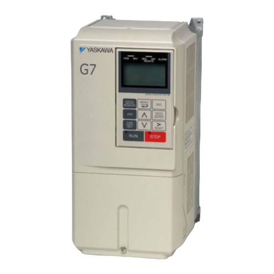
Confirmations upon Delivery Component Names The external appearance and component names of the Inverter are shown in Fig 1.4. The Inverter with the ter- minal cover removed is shown in Fig 1.5. Top protective cover Mounting hole Inverter cover Cooling Mounting hole Front cover... -
Page 24: Exterior And Mounting Dimensions
Exterior and Mounting Dimensions Open Chassis Inverters (IP00) Exterior diagrams of the Open Chassis Inverters are shown below. (5)* (5)* * (10) for 200 V Class Inverters of 30 to 110 kW or 400 V Class Inverters of 55 to 160 kW. 200 V/400 V Class Inverters of 0.4 to 15 kW 200 V Class Inverters of 18.5 to 110 kW 400 V Class Inverters of 18.5 to 160 kW... -
Page 25: Enclosed Wall-Mounted Inverters [Nema1 (Type 1)]
Exterior and Mounting Dimensions Enclosed Wall-mounted Inverters [NEMA1 (Type 1)] Exterior diagrams of the Enclosed Wall-mounted Inverters [NEMA1 (Type 1)] are shown below. (5)* (5)* Grommet * (7.5) for 200 V Class Inverters of 30 to 75 kW or 400 V Class Inverters of 55 to 160 kW. - Page 26 Table 1.3 200 VAC and 400 VAC (0.4 kW to 300 kW) Inverter Dimensions (mm) and Masses (kg) Heat Genera- Max. Dimensions (mm) tion (W) Appli- Voltage cable Open Chassis (IP00) Enclosed Wall-mounted [NEMA1 (Type 1)] Total Cooling Heat Class Motor Method Exter...
-
Page 27: Checking And Controlling The Installation Site
Checking and Controlling the Installation Site Checking and Controlling the Installation Site Install the Inverter in the installation site described below and maintain optimum conditions. Installation Site Install the Inverter under the following conditions and a pollution level of 2 or less (UL standard). Table 1.5 Installation Site Type Ambient Operating Temperature... -
Page 28: Installation Orientation And Space
Installation Orientation and Space Install the Inverter vertically so as not to reduce the cooling effect. When installing the Inverter, always provide the following installation space to allow normal heat dissipation. A mm min. B mm min. 30 mm min. 30 mm min. -
Page 29: Removing And Attaching The Terminal Cover
Removing and Attaching the Terminal Cover Removing and Attaching the Terminal Cover Remove the terminal cover to wire cables to the control circuit and main circuit terminals. Removing the Terminal Cover Inverters of 15 kW or Less Loosen the screws at the bottom of the terminal cover, press in on the sides of the terminal cover in the direc- tion indicated by arrow 1, and then lift the terminal cover up to an angle of about 30 degrees in the direction indicated by arrow 2. -
Page 30: Attaching The Terminal Cover
Attaching the Terminal Cover When wiring the terminal block has been completed, attach the terminal cover by reversing the removal proce- dure. For Inverters with an output of 15 kW or less, insert the tab on the top of the terminal cover into the grove on the Inverter and press in on the bottom of the terminal cover until it clicks into place. -
Page 31: Removing/Attaching The Digital Operator And
Removing/Attaching the Digital Operator and Front Cover Removing/Attaching the Digital Operator and Front Cover The methods of removing and attaching the Digital Operator and Front Cover are described in this sec- tion. Inverters of 15 kW or Less To attach optional boards or change the terminal board connector, remove the Digital Operator and front cover in addition to the terminal cover. - Page 32 Removing the Front Cover Press the left and right sides of the front cover in the directions of arrows 1 and lift the bottom of the cover in the direction of arrow 2 to remove the front cover as shown in the following illustration. Fig 1.12 Removing the Front Cover (Model CIMR-G7A43P7 Shown Above) Mounting the Front Cover After wiring the terminals, mount the front cover to the Inverter by performing in reverse order to the steps to...
- Page 33 Removing/Attaching the Digital Operator and Front Cover Fig 1.13 Mounting the Digital Operator 1. Do not remove or attach the Digital Operator or mount or remove the front cover using methods other than those described above, otherwise the Inverter may break or malfunction due to imperfect contact. 2.
-
Page 34: Inverters Of 18.5 Kw Or More
Inverters of 18.5 kW or More For Inverter with an output of 18.5 kW or more, remove the terminal cover and then use the following proce- dures to remove the Digital Operator and front cover. Removing the Digital Operator Use the same procedure as for Inverters with an output of 18.5 kW or less. -
Page 35: Removing And Attaching The Protection Cover
Removing and Attaching the Protection Cover Removing and Attaching the Protection Cover Inverters of 15 kW or less have protection covers on the top and bottom as shown in Fig. 1.4.Always remove the protection covers before installing an Inverter of 15 kW or less in a panel. Use the following procedure to remove and attach a protection cover. -
Page 36: Attaching The Protection Cover
Attaching the Protection Cover Top Protection Cover The protection cover has four hooks: two hooks on the bottom and two on the sides. Fit the bottom hooks into the holes, bend the cover slightly, and press the cover down until the hooks on the side snap. Holes for bottom hooks Fig 1.17 Attaching the Top Protection Cover (Model CIMR-G7A43P7 Shown Above) Bottom Protection Cover... -
Page 37: Wiring
Wiring This chapter describes wiring terminals, main circuit terminal connections, main circuit termi- nal wiring specifications, control circuit terminals, and control circuit wiring specifications. Connections to Peripheral Devices......2-2 Ground Fault Interrupters, Molded-case Circuit Breakers, and Magnetic Contactors......2-4 Precautions when Using Peripheral Devices....2-6 Connection Diagram ............2-8 Terminal Block Configuration ........2-10 Wiring Main Circuit Terminals ........ -
Page 38: Connections To Peripheral Devices
Connections to Peripheral Devices This table summarizes connections between the Inverter and peripheral devices. Purpose Name Model (Code) Descriptions Connect a ground fault interrupter or MCCB to the power sup- ply line to protect Inverter wiring and to prevent secondary Ground Fault Inter- Protect Inverter wiring and NV... - Page 39 L5-02 is 0 (fault output not active during restart attempt). * 3. The finemet zero-phase reactor is manufactured by Hitachi Metals. * 4. To use the Separate Power Supply Unit, a dedicated Inverter Unit to handle the separate power supply is required. Contact your Yaskawa representative for details.
-
Page 40: Ground Fault Interrupters, Molded-Case Circuit Breakers, And Magnetic Contactors
Ground Fault Interrupters, Molded-case Circuit Breakers, and Magnetic Contactors Always connect a ground fault interrupter or molded-case circuit breaker between the AC main circuit power supply and the Varispeed G7 R, S, and T input terminals. Connect a magnetic contactor as neces- sary. - Page 41 Ground Fault Interrupters, Molded-case Circuit Breakers, and Magnetic Contactors 400 V Class Motor Varispeed Ground Fault Interrupter Molded-case Circuit Breaker Magnetic Contactor Capacity G7 Model Without With Reactor Without With Reactor Without With Reactor (kW) CIMR- Reactor Reactor Reactor G7A Model Rated Model Rated Model Rated...
-
Page 42: Precautions When Using Peripheral Devices
Precautions when Using Peripheral Devices Selecting and Installing a Ground Fault Interrupter or Molded-Case Circuit Breaker A ground fault interrupter (ELCB) is recommended as a general rule to protect Inverter wiring and to prevent secondary damage when a fault occurs. A molded-case circuit breaker (MCCB) can also be used if permitted by the power system. -
Page 43: Power Factor Improvement (Elimination Of Phase-Advancing Capacitors)
Precautions when Using Peripheral Devices Power Factor Improvement (Elimination of Phase-advancing Capacitors) Install a DC reactor or an AC reactor on the power supply side of the Inverter to improve the power factor. (DC reactors are built into 200 V Class models for 18.5 to 110 kW and 400 V Class models for 18.5 to 300 kW.) The capacitor to improve the power factor and the surge absorber on the Inverter output side may overheat or become damaged due to the harmonic components of Inverter output. -
Page 44: Connection Diagram
Connection Diagram The connection diagram of the Inverter is shown in Fig 2.2. When using the Digital Operator, the motor can be operated by wiring only the main circuits. Thermal relay Thermal switch contact trip contact Braking Unit (optional) Level Motor detector 2MCCB... - Page 45 Connection Diagram 1. Control circuit terminals are arranged as shown below. IMPORTANT 2. The output current capacity of the +V and −V terminals are 20 mA. Do not short-circuit between the +V, −V, and AC terminals. Doing so may result in a malfunction or a breakdown of the Inverter. 3.
-
Page 46: Terminal Block Configuration
Terminal Block Configuration The terminal arrangement for 200 V Class Inverters are shown in Fig 2.3 and Fig 2.4. Control circuit terminals Main circuit terminals Charge indicator Ground terminal Fig 2.3 Terminal Arrangement (200 V Class Inverter for 0.4 kW Shown Above) Control circuit terminals Charge indicator Main circuit terminals... -
Page 47: Wiring Main Circuit Terminals
Wiring Main Circuit Terminals Wiring Main Circuit Terminals Applicable Wire Sizes and Closed-loop Connectors Select the appropriate wires and crimp terminals from Table 2.1 to Table 2.3. Refer to instruction manuals TOBPC72060000/TOBPC72060001 for wire sizes for Braking Resistor Units and Braking Units. Table 2.1 200 V Class Wire Sizes Inverter Recom-... - Page 48 Table 2.1 200 V Class Wire Sizes (Continued) Inverter Recom- Possible Tightening Model Termi- mended Wire Sizes Terminal Symbol Torque Wire Type Wire Size CIMR- Screws (N•m) (AWG) (AWG) G7A R/L1, S/L2, T/L3, 1 U/T1, 60 to 100 17.6 to 22.5 (2/0 to 4/0) (3/0) V/T2, W/T3, R1/L11, S1/L21, T1/L31...
- Page 49 Wiring Main Circuit Terminals Note The wire thickness is set for copper wires at 75°C. Table 2.2 400 V Class Wire Sizes Inverter Recom- Possible Tightening Termi- Model mended Wire Sizes Terminal Symbol Torque Wire Type Wire Size CIMR- Screws (N•m) (AWG) (AWG)
- Page 50 Table 2.2 400 V Class Wire Sizes (Continued) Inverter Recom- Possible Tightening Model Termi- mended Wire Sizes Terminal Symbol Torque Wire Type Wire Size CIMR- Screws (N•m) (AWG) (AWG) G7A R/L1, S/L2, T/L3, 1, U/T1, V/T2, 50 to 60 9.0 to 10.0 W/T3, R1/L11, S1/L21, T1/L31 (1 to 1/0) (1/0)
- Page 51 Wiring Main Circuit Terminals Table 2.2 400 V Class Wire Sizes (Continued) Inverter Recom- Possible Tightening Model Termi- mended Wire Sizes Terminal Symbol Torque Wire Type Wire Size CIMR- Screws (N•m) (AWG) (AWG) G7A 100 to 325 150 × 2P R/L1, S/L2, T/L3 78.4 to 98 (4/0 to 600)
- Page 52 Table 2.3 Closed-loop Crimp Terminal and Insulation Cap Sizes (200 V Class and 400 V Class) (Continued) Inverter Wire Size sq (AWG) Crimping Tool Closed-loop Lug Kit Product Model Terminal Crimp Insulation Cap CIMR- Screws R/L1, S/L2, and U/T1, V/T2, and Terminals Tool Model G7A...
- Page 53 Wiring Main Circuit Terminals Table 2.3 Closed-loop Crimp Terminal and Insulation Cap Sizes (200 V Class and 400 V Class) (Continued) Inverter Wire Size sq (AWG) Crimping Tool Closed-loop Lug Kit Product Model Terminal Crimp Insulation Cap CIMR- Screws R/L1, S/L2, and U/T1, V/T2, and Terminals Tool Model...
-
Page 54: Main Circuit Terminal Functions
Table 2.3 Closed-loop Crimp Terminal and Insulation Cap Sizes (200 V Class and 400 V Class) (Continued) Inverter Wire Size sq (AWG) Crimping Tool Closed-loop Lug Kit Product Model Terminal Crimp Insulation Cap CIMR- Screws R/L1, S/L2, and U/T1, V/T2, and Terminals Tool Model G7A... -
Page 55: Main Circuit Configurations
400/ Note 1. Consult your Yaskawa representative before using 12-phase rectification. Note 2. When installing a molded-case circuit breaker (MCCB) on the DC power supply side, do not use it to turn the Inverter power supply ON and OFF. -
Page 56: Standard Connection Diagrams
If a Braking Unit or a Braking Resistor Unit is connected to a wrong terminal, the Inverter, Braking Unit, or Braking Resistor Unit can be damaged. Refer to FOR YASKAWA AC Drive Option Braking Unit, Braking Resistor Unit Installation Manual (TOB- PC72060000) for connecting the Inverter with a Braking Unit or a Braking Resistor Unit. -
Page 57: Wiring The Main Circuits
Wiring Main Circuit Terminals Wiring the Main Circuits This section describes wiring connections for the main circuit inputs and outputs. Wiring Main Circuit Inputs Observe the following precautions for wiring the main circuit power supply inputs. Installing a Ground Fault Interrupter Always connect the power input terminals (R, S, and T) and power supply through a ground fault interrupter (ELCB) that is suitable for the Inverter. - Page 58 Installing a Magnetic Contactor If the power supply for the main circuit is to be shut off during a sequence, a magnetic contactor can be used. When a magnetic contactor is installed on the primary side of the main circuit to forcibly stop the Inverter, however, the regenerative braking does not work and the Inverter will coast to a stop.
- Page 59 Wiring Main Circuit Terminals Incorrect Noise Filter Installation • Power supply ELCB Inverter MCCB General- Other purpose controllers noise filter Power ELCB supply General- Inverter purpose noise filter MCCB Other controllers Do not use general-purpose noise filters. No general- purpose noise filter can effectively suppress noise generated from the Inverter.
- Page 60 Operating the Varispeed G7 without operating the D1000 or shutting down the power supply while the D1000 is operating may cause converter faults. * 6. For information on the interlock with the Inverter, refer to 4.5 Operation with the Drive Connected in the Power Regenerative Converter YASKAWA D1000 Series Instruction Manual (TOBP C710656 04).
- Page 61 Wiring Main Circuit Terminals * 11.Observe the following precautions when installing a breaker (or contactor) for emergency shutdowns on the D1000 (DC) side. •First confirm that the Inverter and D1000 CHARGE indicators are not lit before turning ON the breaker (or contactor) on the D1000 output (DC) side. If the breaker is turned ON during voltage charging, overcurrent will flow and there is a risk of damage to the parts.
- Page 62 Installing a Noise Filter on Output Side Connect a noise filter to the output side of the Inverter to reduce radio noise and inductive noise. Power ELCB supply Noise Inverter filter Radio noise AM radio Inductive Signal line noise Controller Inductive Noise: Electromagnetic induction generates noise on the signal line, causing the controller to malfunction.
- Page 63 Wiring Main Circuit Terminals Countermeasures Against Radio Interference Radio noise is generated from the Inverter as well as from the input and output lines. To reduce radio noise, install noise filters on both input and output sides, and also install the Inverter in a totally enclosed steel box. The cable between the Inverter and the motor should be as short as possible.
- Page 64 Connecting the Braking Resistor (ERF) A Braking Resistor that mounts to the Inverter can be used with 200 V and 400 V Class Inverters with outputs from 0.4 to 3.7 kW. Connect the braking resistor as shown in Fig 2.13. Table 2.7 L8-01 (Protect selection for internal DB resistor) 1 (Enables overheat protection)
-
Page 65: Wiring Control Circuit Terminals
Wiring Control Circuit Terminals Wiring Control Circuit Terminals Wire Sizes and Closed-loop Connectors For remote operation using analog signals, keep the control line length between the Digital Operator or opera- tion signals and the Inverter to 50 m or less, and separate the lines from high-power lines (main circuits or relay sequence circuits) to reduce induction from peripheral devices. - Page 66 Straight Solderless Terminals for Signal Lines Models and sizes of straight solderless terminal are shown in the following table. Table 2.10 Straight Solderless Terminal Sizes Model Manufacturer Wire Size mm (AWG) 0.25 (24) AI 0.25 - 8YE 12.5 0.5 (20) AI 0.5 - 8WH 0.75 (18) AI 0.75 - 8GY...
-
Page 67: Control Circuit Terminal Functions
Wiring Control Circuit Terminals Control Circuit Terminal Functions The functions of the control circuit terminals are shown in Table 2.11. Use the appropriate terminals for the correct purposes. Table 2.11 Control Circuit Terminals Signal Name Function Signal Level Type Forward Run/Stop Command Forward run when ON;... - Page 68 Table 2.11 Control Circuit Terminals (Continued) Signal Name Function Signal Level Type Factory setting: Zero-speed Multi-function PHC output 1 Zero-speed level (b2-01) or below when ON. Factory setting: Frequency agreement detec- tion Multi-function PHC output 2 Frequency within 2 Hz of set frequency when ON.
- Page 69 Wiring Control Circuit Terminals Flywheel diode The rating of the flywheel diode Coil must be at least as high as the External power: 50 mA max. circuit voltage. 48 V max. Fig 2.17 Flywheel Diode Connection Shunt Connector CN5 and DIP Switch S1 The shunt connector CN 5 and DIP switch S1 are described in this section.
- Page 70 Table 2.13 Sinking/Sourcing Mode and Input Signals Internal Power Supply External Power Supply CN5 (NPN set) Factory setting CN5 (EXT set) Shunt IP24V (24 V) IP24V (24 V) External +24 V position Sink- Mode CN5 (PNP set) CN5 (EXT set) External + 24 V IP24V (24 V) IP24V (24 V)
-
Page 71: Control Circuit Terminal Connections
Wiring Control Circuit Terminals Control Circuit Terminal Connections Connections to Inverter control circuit terminals are shown in Fig 2.19. Inverter CIMR-G7A2018 Forward Run/Stop Reverse Run/Stop Thermal switch contact for Braking Unit External fault Fault reset Multi-step command 1 (Main speed switching) Multi-step speed setting 2 Jog frequency... -
Page 72: Control Circuit Wiring Precautions
Control Circuit Wiring Precautions Observe the following precautions when wiring control circuits. Separate control circuit wiring from main circuit wiring (terminals R/L1, S/L2, T/L3, B1, B2, U/T1, V/T2, • W/T3, 2, and 3) and other high-power lines. Separate wiring for control circuit terminals MA, MB, MC, M1, and M2 (contact outputs) from wiring to •... -
Page 73: Wiring Check
Wiring Check Wiring Check Checks Check all wiring after wiring has been completed. Do not perform a buzzer check on control circuits. Perform the following checks on the wiring. Is all wiring correct? • Have any wire clippings, screws, or other foreign material been left? •... -
Page 74: Installing And Wiring Option Boards
Installing and Wiring Option Boards Option Board Models and Specifications Up to three option boards can be mounted in the Inverter. You can mount up one Board into each of the three places on the control board (A, C, and D) shown in Fig 2.21. Table 2.14 lists the type of option boards and their specifications. -
Page 75: Installation
Installing and Wiring Option Boards Installation When installing an option board, turn OFF the input power supply and wait for 5 minutes or longer. Remove the terminal cover and confirm that the CHARGE indicator inside the Inverter is not lit. After confirming that the CHARGE indicator is not lit, remove the Digital Operator and front cover and then install the option board. -
Page 76: Pg Speed Control Board Terminals And Specifications
PG Speed Control Board Terminals and Specifications The terminal specifications for the PG Speed Control Boards are given in the following tables. PG-A2 The terminal specifications for the PG-A2 are given in the following table. Table 2.15 PG-A2 Terminal Specifications Terminal Contents Specifications... - Page 77 Installing and Wiring Option Boards PG-D2 The terminal specifications for the PG-D2 are given in the following table. Table 2.17 PG-D2 Terminal Specifications Terminal Contents Specifications 12 VDC (±5%), 200 mA max.* Power supply for pulse generator 0 VDC (GND for power supply) 5 VDC (±5%), 200 mA max.* Pulse input + terminal Line driver input (RS-422 level input)
-
Page 78: Wiring
Wiring Wiring examples are provided in the following illustrations for the option boards. Wiring the PG-A2 Wiring examples are provided in the following illustrations for the PG-A2. Inverter Three-phase, 200 VAC (400 VAC) R/L1 U/T1 S/L2 V/T2 T/L3 W/T3 PC-A2 +12 V power supply... - Page 79 Installing and Wiring Option Boards Wiring the PG-B2 Wiring examples are provided in the following illustrations for the PG-B2. Inverter Three-phase, 200 VAC (400 VAC) Power supply +12 V Power supply 0 V A-phase pulse output (+) A-phase pulse output (-) B-phase pulse output (+) B-phase pulse output (-) A-phase pulse monitor output...
- Page 80 Wiring the PG-D2 Wiring examples are provided in the following illustrations for the PG-D2. Inverter Three-phase, 200 VAC (400 VAC) Power supply +12 V Power supply 0 V Power supply +5 V Pulse input + (A/B phase) Pulse input - (A/B phase) Pulse monitor output •...
-
Page 81: Wiring Terminal Blocks
Installing and Wiring Option Boards Wiring Terminal Blocks Use no more than 100 meters of wiring for PG (encoder) signal lines, and keep them separate from power lines. Use shielded, twisted-pair wires for pulse inputs and pulse output monitor wires, and connect the shield to the shield connection terminal. -
Page 82: Selecting The Number Of Pg (Encoder) Pulses
Selecting the Number of PG (Encoder) Pulses The setting for the number of PG pulses depends on the model of PG Speed Control Board being used. Set the correct number for your model. PG-A2/PG-B2 The maximum response frequency is 32,767 Hz. Use a PG that outputs a maximum frequency of approximately 20 kHz for the rotational speed of the motor. - Page 83 Installing and Wiring Option Boards PG-D2/PG-X2 There are 5 V and 12 V PG power supplies. Check the PG power supply specifications before connecting. The maximum response frequency is 300 kHz. Use the following equation to computer the output frequency of the PG (f −1 Motor speed at maximum frequency output (min (Hz) =...
-
Page 84: Digital Operator And Modes
Digital Operator and Modes This chapter describes Digital Operator displays and functions, and provides an overview of operating modes and switching between modes. Digital Operator............3-2 Modes ................3-5... -
Page 85: Digital Operator
Digital Operator This section describes the displays and functions of the Digital Operator. Digital Operator Display The key names and functions of the Digital Operator are described below. Drive Mode Indicators (LED) FWD: Lit when there is a Forward Run Command input. REV: Lit when there is a Reverse Run Command input. - Page 86 Digital Operator Table 3.1 Key Functions (Continued) Name Function Selects the rotation direction of the motor when the Inverter is being FWD/REV Key operated from the Digital Operator. Sets the number of digits for user constant settings. Shift/RESET Key Also acts as the Reset Key when a fault has occurred. Selects menu items, sets user constant numbers, and increments set Increment Key values.
- Page 87 The following table shows the relationship between the indicators on the RUN and STOP Keys and the Inverter conditions. The indicators are lit, unlit or blinking reflecting the order of priority. Table 3.2 Relation of Inverter to RUN and STOP Indicators STOP Inverter Priority...
-
Page 88: Modes
Modes Modes This section describes the Inverter's modes and switching between modes. Inverter Modes The Inverter's user constants and monitoring functions are organized in groups called modes that make it eas- ier to read and set user constants.The Inverter is equipped with 5 modes. The 5 modes and their primary functions are shown in the Table 3.3. -
Page 89: Switching Modes
Switching Modes The mode selection display will appear when the MENU Key is pressed from a monitor or setting display. Press the MENU Key from the mode selection display to switch between the modes. Press the DATA/ENTER Key from the mode selection key to monitor data and from a monitor display to access the setting display. -
Page 90: Drive Mode
Modes Drive Mode Drive mode is the mode in which the Inverter can be operated. The following monitor displays are possible in drive mode: The frequency reference, output frequency, output current, and output voltage, as well as fault information and the fault history. When b1-01 (Reference selection) is set to 0, the frequency can be changed from the frequency setting display. -
Page 91: Quick Programming Mode
Note When changing the display with the Increment and Decrement Keys, the next display after the one for the last parameter number will be the one for the first parameter number and vise versa. For example, the next display after the one for U1-01 will be U1-40. This is indicated in the figures by the letters A and B and the numbers 1 to 6. - Page 92 Modes Frequency Setting Display Mode Selection Display Monitor Display MENU -DRIVE- ** Main Menu ** Operation MENU DATA DATA ENTER -QUICK- -QUICK- -QUICK- ENTER Control Method Control Method ** Main Menu ** A1-02=2 A1-02= Quick Setting Open Loop Vector Open Loop Vector MENU DATA -QUICK-...
-
Page 93: Advanced Programming Mode
Advanced Programming Mode In advanced programming mode, all Inverter constants can be monitored and set. Constants can be changed from the setting displays. Use the Increment, Decrement, and Shift/RESET Keys to change the frequency. The user constant will be written and the monitor display will be returned to when the DATA/ENTER Key is pressed after changing the setting. - Page 94 Modes Setting User Constants Here, the procedure is shown to change C1-01 (Acceleration Time 1) from 10 s to 20 s. Table 3.4 Setting User Constants in Advanced Programming Mode Step Digital Operator Display Description -DRIVE- Frequency Ref Turn ON the power supply. U1- 01=60.00Hz U1-02=60.00Hz U1-03=10.05A...
- Page 95 External Fault Setting Procedure Examples of the Digital Operator displays that appear when setting an eternal error for a multi-function con- tact input in Advanced Programming Mode are shown in the following diagram. Mode Selection Display Monitor Display Setting Display DATA DATA ENTER...
-
Page 96: Verify Mode
Modes Verify Mode Verify mode is used to display any constants that have been changed from their default settings in a program- ming mode or by autotuning. “None” will be displayed if no settings have been changed. Of the environment mode settings, only A1-02 will be displayed if it has been changed. Other environment modes settings will not be displayed even if they have been changed from their default settings. -
Page 97: Autotuning Mode
Always perform autotuning before starting operation. When V/f control has been selected, stationary autotuning for only line-to-line resistance can be selected. When the motor cannot be disconnected from the load, perform stationary autotuning. Contact your Yaskawa representatives to set motor constants by calculation. - Page 98 Modes Mode Selection Display Monitor Display Setting Display DATA ENTER -VERIFY- ** Main Menu ** Modified Consts MENU DATA DATA ENTER -A.TUNE- -A.TUNE- -A.TUNE- ENTER Tuning Mode Sel Tuning Mode Sel ** Main Menu ** =0 *0* T1- 01 = Auto-Tuning Standard Tuning Standard Tuning...
-
Page 99: Trial Operation
Trial Operation This chapter describes the procedures for trial operation of the Inverter and provides an example of trial operation. Overview of Trial Operation Procedure......4-2 Trial Operation Procedures..........4-3 Adjustment Suggestions ..........4-29... -
Page 100: Overview Of Trial Operation Procedure
Overview of Trial Operation Procedure Perform trial operation according to the following flowchart. START Installation and Mounting Wiring and Connections Refer to page 4-3. Setting the Power Supply Voltage Jumper* Refer to page 4-3. Power ON Refer to page 4-4. Checking the Display Status Refer to page 4-4. -
Page 101: Trial Operation Procedures
Trial Operation Procedures Trial Operation Procedures The procedure for the trial operate is described in order in this section. Setting the Power Supply Voltage Jumper (400 V Class Inverters of 55 kW or Higher) Set the power supply voltage jumper after setting E1-01 (Input Voltage Setting) for 400 V Class Inverters of 55 kW or higher. -
Page 102: Checking The Display Status
Checking the Display Status If the Digital Operator's display at the time the power is connected is normal, it will read as follows: -DRIVE- -DRIVE- Frequency Ref Frequency Ref The frequency reference monitor is dis- Display for normal operation U1- 01= 60.0 0Hz U1-01= 0 0 0.0 0Hz played in the data display section. - Page 103 Trial Operation Procedures V/f Control (A1-02 = 0) Set either one of the fixed patterns (0 to E) in E1-03 (V/f Pattern Selection) or set F in E1-03 to specify a • user-set pattern as required for the motor and load characteristics in E1-04 to E1-13 in advanced program- ming mode.
-
Page 104: Settings For The Control Methods
Settings for the Control Methods Autotuning methods depend on the control method set for the Inverter. Make the settings required by the con- trol method. Overview of Settings Make the required settings in quick programming mode and autotuning mode according to the following flow- chart. -
Page 105: Basic Settings
Trial Operation Procedures Basic Settings Switch to the quick programming mode (“QUICK” will be displayed on the LCD screen) and then set the fol- lowing user constants. Refer to Chapter 3 Digital Operator and Modes for Digital Operator operating proce- dures and to Chapter 5 User Constants and Chapter 6 Constant Settings by Function for details on the user constants. - Page 106 Table 4.1 Basic User Constant Settings (Continued) : User constants that must be set, : User constants to be set as necessary. Con- Cate- Setting Factory stant Name Description Page gory Range Setting Number Frequency ref- d1-01 to d1-01 to erences 1 to 4 d1-04: Set the required speed references for...
-
Page 107: Autotuning
Trial Operation Procedures Autotuning Use the following procedure to perform autotuning to automatically set motor constants when using the vector control method, when the cable length is long, etc. If the control method was changed after autotuning, be sure to perform autotuning again. One of the following four autotuning modes can be set. - Page 108 Tuning Mode Multi-function Inputs Multi-function Outputs Same as during normal Rotational autotuning Do not function. operation Maintain same status as Stationary autotuning 1 Do not function. when autotuning is started. Stationary autotuning for line- Maintain same status as Do not function. to-line resistance only when autotuning is started.
- Page 109 Trial Operation Procedures Set the autotuning type. Step Digital Operator Display Turn ON the power supply. Initial display Press the MENU Key several times to access the autotuning display. The autotuning display will not appear during operation or when a fault has occurred.
- Page 110 Enter the motor nameplate data. When the autotuning type has been selected, enter the motor information based on the motor nameplate data. Step Digital Operator Display Press the Increment Key to display T1-02 (Motor Output Power). Press the DATA/ENTER Key to display the current set value of T1-02. Set the output power of the motor in kilowatts.
- Page 111 Trial Operation Procedures Start autotuning. Step Digital Operator Display Press the Increment Key to access the start autotuning display. Press the RUN Key to start autotuning. Autotuning will end in 1 or 2 minutes. When autotuning has been completed, press the MENU Key to change the mode.
- Page 112 tionary autotuning1 again and run the motor using the aforementioned procedure under the recommended conditions or perform stationary autotuning 2 or rotational autotuning. Usually the standard setting for E2-02 is 1 Hz to 3 Hz, and that for E2-03 is 30% to 65% of the rated current for a general-purpose motor.
- Page 113 Trial Operation Procedures Enter the motor nameplate data. When the autotuning type has been selected, enter the motor information based on the motor nameplate data. Step Digital Operator Display Press the Increment Key to display T1-02 (Motor Output Power). Press the DATA/ENTER Key to display the current set value of T1-02. Set the output power of the motor in kilowatts.
- Page 114 Start autotuning. Step Digital Operator Display Press the Increment Key to access the start autotuning display. Press the RUN Key to start autotuning. Autotuning will end in 1 or 2 minutes. When autotuning has been completed, press the MENU Key to change the mode.
- Page 115 Trial Operation Procedures Set the autotuning type. Step Digital Operator Display Turn ON the power supply. Initial display Press the MENU Key several times to access the autotuning display. The autotuning display will not appear during operation or when a fault has occurred.
- Page 116 Enter the motor nameplate data. When the autotuning type has been selected, enter the motor information based on the motor nameplate data. Step Digital Operator Display Press the Increment Key to display T1-02 (Motor Output Power). Press the DATA/ENTER Key to display the current set value of T1-02. Set the output power of the motor in kilowatts.
- Page 117 (motor exciting current) from motor examination results to T1-09. After auto- tuning, the value of T1-09 will be written in E2-03. When not setting T1-09, the value of Yaskawa standard motor’s no-load current will be written in E2-03.
- Page 118 Set the autotuning type. Step Digital Operator Display Turn ON the power supply. Initial display Press the MENU Key several times to access the autotuning display. The autotuning display will not appear during operation or when a fault has occurred. Press the DATA/ENTER Key to display the T1-01 (Autotuning Mode Selection) user constant setting.
- Page 119 Trial Operation Procedures Enter the motor nameplate data. When the autotuning type has been selected, enter the motor information based on the motor nameplate data. Step Digital Operator Display Press the Increment Key to display T1-02 (Motor Output Power). Press the DATA/ENTER Key to display the current set value of T1-02. Set the output power of the motor in kilowatts.
- Page 120 Start autotuning. Step Digital Operator Display Press the Increment Key to access the start autotuning display. Press the RUN Key to start autotuning. Autotuning will end in 1 or 2 minutes. When autotuning has been completed, press the MENU Key to change the mode.
- Page 121 Trial Operation Procedures Precautions for Rotational and Stationary Autotuning Lower the base voltage based on Fig 4.4 to prevent saturation of the Inverter’s output voltage when the rated voltage of the motor is higher than the voltage of the power supply to the Inverter. Use the following proce- dure to perform autotuning.
- Page 122 If the values of E2-02 and E2-03 differed greatly from the reference data of the motor in the test report or the instruction manual, hunting, motor vibrations, insufficient motor torque, or an overcurrent may occur because the motor is operated although the aforementioned conditions have not been fulfilled after stationary autotun- ing 1.
- Page 123 Trial Operation Procedures Constant Settings for Autotuning The following constants must be set before autotuning. Table 4.2 Constant Settings before Autotuning Name Data Displays during Autotuning Con- Open Open stant Setting Factory Flux Display -loop -loop Num- Range Setting Display with Vec-...
- Page 124 Table 4.2 Constant Settings before Autotuning (Continued) Name Data Displays during Autotuning Con- Open Open stant Setting Factory Flux Display -loop -loop Num- Range Setting Display with Vec- Vec- Vec- tor 1 tor 2 Motor base speed Set the base speed of the motor 1750 T1-07 0 to 24000...
-
Page 125: Application Settings
Trial Operation Procedures Application Settings User constants are set as required in advanced programming mode (“ADV” will be displayed on the LCD screen). All the constants that can be set in quick programming mode can also be displayed and set in advanced programming mode. -
Page 126: Check And Recording User Constants
Operation using the Digital Operator Use the Digital Operator to start operation in LOCAL mode in the same way as in no-load operation. • If fault occurs during operation, make sure the STOP Key on the Digital Operator is easily accessible. •... -
Page 127: Adjustment Suggestions
Adjustment Suggestions Adjustment Suggestions If hunting, vibration, or other problems originating in the control system occur during trial operation, adjust the constants listed in the following table according to the control method. This table lists only the most commonly used user constants. Table 4.3 Adjusted User Constants Recom- Control... - Page 128 Table 4.3 Adjusted User Constants (Continued) Recom- Control Name (Constant Factory Performance mended Adjustment Method Method Number) Setting Setting • Reducing motor • Increase the setting if magnetic noise motor magnetic noise is Depends Carrier frequency • Controlling hunting 0 to high.
- Page 129 Adjustment Suggestions Table 4.3 Adjusted User Constants (Continued) Recom- Control Name (Constant Factory Performance mended Adjustment Method Method Number) Setting Setting Set the output frequency at Switching the ASR which to change the ASR proportional gain and 0.0 to max. proportional gain and inte- ASR switching integral time accord-...
- Page 130 Table 4.3 Adjusted User Constants (Continued) Recom- Control Name (Constant Factory Performance mended Adjustment Method Method Number) Setting Setting N4-11 (Speed Countermeasure when Reduce the values of N4-11 estimator switching N4-11: shock is a problem and N4-28. (Typically, 5 Hz.) frequency) 70 Hz Lower than...
- Page 131 Adjustment Suggestions Procedure for Increasing the Speed Response (PRG 102 only) Increase the speed response. Increase the setting for the ASR proportional gain (C5-01). C5-01 ≥ 30.0 (Typically, increase in intervals of 5.) Reduce the setting for the ASR primary delay time (C5-06). C5-06 ≤...
- Page 132 Table 4.4 Constants Indirectly Affecting Control and Applications (Continued) Name (Constant Number) Application Set the maximum torque during vector control. If a setting is increased, Torque limits (L7-01 to L7-04, L7-06, L7-07) use a motor with higher capacity than the Inverter. If a setting is reduced, stalling can occur under heavy loads.
-
Page 133: User Constants
User Constants This chapter describes all user constants that can be set in the Inverter. User Constant Descriptions .........5-2 Digital Operation Display Functions and Levels ..5-3 User Constant Tables ..........5-9... -
Page 134: User Constant Descriptions
User Constant Descriptions This section describes the contents of the user constant tables. Description of User Constant Tables User constant tables are structured as shown below. Here, b1-01 (Frequency Reference Selection) is used as an example. Name Control Methods Change MEMO- Open... -
Page 135: Digital Operation Display Functions And Levels
Digital Operation Display Functions and Levels Digital Operation Display Functions and Levels The following figure shows the Digital Operator display hierarchy for the Inverter. Function Display Page Status Monitor Constants Monitor 5-79 MENU Drive Mode Fault Trace 5-87 Fault Trace Fault History 5-89 Fault History... -
Page 136: User Constants Settable In Quick Programming Mode
User Constants Settable in Quick Programming Mode The minimum user constants required for Inverter operation can be monitored and set in quick programming mode. The user constants displayed in quick programming mode are listed in the following table. These, and all other user constants, are also displayed in advanced programming mode. - Page 137 Digital Operation Display Functions and Levels Name Control Methods Change MEMO- Open Open Con- Setting Factory during -loop Flux Loop Description stant Range Setting Opera- Regis- Display with Vec- Vec- Vec- Number tion Carrier fre- Select carrier frequency when open- quency for loop vector 2 control is used.
- Page 138 Name Control Methods Change MEMO- Open Open Con- Setting Factory during -loop Flux Loop Description stant Range Setting Opera- Regis- Display with Vec- Vec- Vec- Number tion Max. output 40.0 to frequency 60.0 Hz E1-04 303H 400.0 (FMAX) Frequency Max. voltage 0.0 to 200.0...
- Page 139 Digital Operation Display Functions and Levels Name Control Methods Change MEMO- Open Open Con- Setting Factory during -loop Flux Loop Description stant Range Setting Opera- Regis- Display with Vec- Vec- Vec- Number tion Gain (ter- Set the voltage level gain for multi- minal FM) function analog output 1.
- Page 140 * 7. The setting range for open-loop vector 2 control is 0 to 66.0 (0 to 132.0 for PRG 103). For the 400 V Class, there are limitations on the maximum output frequency depending on the setting for the carrier frequency and capacity. The maximum output frequency for 400 V, 90 to 110 kW is 250 Hz.
-
Page 141: User Constant Tables
User Constant Tables User Constant Tables A: Setup Settings The following settings are made with the environment constants (A constants): Language displayed on the Digital Operator, access level, control method, initialization of constants. Initialize Mode: A1 User constants for the environment modes are shown in the following table. Name Control Methods Change... - Page 142 Name Control Methods Change MEMO- Open Open Con- during Setting Factory Loop Flux Loop Description stant Page Range Setting Opera- Regis- Display with Vec- Vec- Vec- Number tion Initialize Used to initialize the con- stants using the specified method. No initializing 1110: Initializes using the User constants 0 to...
-
Page 143: B: Application Constants
User Constant Tables b: Application Constants The following settings are made with the application constants (B constants): Operation method selection, DC injection braking, speed searching, timer functions, dwell functions, droop control, energy saving control, and zero-servo control. Operation Mode Selections: b1 User constants for operation mode selection are shown in the following table. - Page 144 Name Control Methods Change MEMO- Open Open Con- during Setting Factory Loop Flux Loop Description stant Page Range Setting Opera- Regis- Display with Vec- Vec- Vec- Number tion Operation Used to set the method of selection operation when the fre- for setting quency reference input is less E1-09 or...
- Page 145 User Constant Tables DC Injection Braking: b2 User constants for injection braking are shown in the following table. Name Control Methods Change MEMO- Open Open Con- Setting Factory during Description Loop Flux Loop stant Page Range Setting Opera- Regis- Display with Vec- Vec-...
- Page 146 Speed Search: b3 User constants for the speed search are shown in the following table. Name Control Methods Change MEMO- Open Open Con- Setting Factory during Loop Flux Loop Description stant Page Display Range Setting Opera- Regis- with Vec- Vec- Vec- Number tion...
- Page 147 User Constant Tables Name Control Methods Change MEMO- Open Open Con- Setting Factory during Loop Flux Loop Description stant Page Range Setting Opera- Regis- Display with Vec- Vec- Vec- Number tion Speed Operation restarts at a speed search obtained by multiplying the detection speed from the speed search by compensa-...
- Page 148 Timer Function: b4 User constants for timer functions are shown in the following table. Name Control Methods Change MEMO- Open Open Con- Setting Factory during Loop Flux Loop Description stant Page Display Range Setting Opera- Regis- with Vec- Vec- Vec- Number tion Timer func-...
- Page 149 User Constant Tables Name Control Methods Change MEMO- Open Open Con- Setting Factory during Loop Flux Loop Description stant Page Range Setting Opera- Regis- Display with Vec- Vec- Vec- Number tion PID upper Sets the upper limit after PID- 0.0 to limit b5-06 control as a percentage of the...
- Page 150 Name Control Methods Change MEMO- Open Open Con- Setting Factory during Loop Flux Loop Description stant Page Range Setting Opera- Regis- Display with Vec- Vec- Vec- Number tion PID sleep function operation Set the PID sleep function 0.0 to b5-15 0.0 Hz 1B3H 6-110...
- Page 151 User Constant Tables Droop Control: b7 User constants for droop functions are shown in the following table. Name Control Methods Change MEMO- Open Open Con- Setting Factory during Description Loop Flux Loop stant Page Range Setting Opera- Regis- Display with Vec- Vec- Vec-...
- Page 152 Energy Saving: b8 User constants for energy-saving control functions are shown in the following table. Name Control Methods Change MEMO- Open Open Con- Setting Factory during Loop Flux Loop Description stant Page Display Range Setting Opera- Regis- with Vec- Vec- Vec- Number tion...
- Page 153 User Constant Tables Zero-servo: b9 User constants for dwell functions are shown in the following table. Name Control Methods Change MEMO- Open Open Con- Setting Factory during Loop Flux Loop Description stant Page Display Range Setting Opera- Regis- with Vec- Vec- Vec- Number...
-
Page 154: C: Autotuning Constants
C: Autotuning Constants The following settings are made with the autotuning constants (C constants): Acceleration/deceleration times, s-curve characteristics, slip compensation, torque compensation, speed control, and carrier frequency func- tions. Acceleration/Deceleration: C1 User constants for acceleration and deceleration times are shown in the following table. Name Control Methods Change... - Page 155 User Constant Tables Name Control Methods Change MEMO- Open Open Con- Setting Factory during Loop Flux Loop Description stant Page Range Setting Opera- Regis- Display with Vec- Vec- Vec- Number tion Accel/decel time setting 0: 0.01-second units 4-33 unit C1-10 0 or 1 209H 1: 0.1-second units...
- Page 156 Motor Slip Compensation: C3 User constants for slip compensation are shown in the following table. Name Control Methods Change MEMO- Open Open Con- Setting Factory during Loop Flux Loop Description stant Page Display Range Setting Opera- Regis- with Vec- Vec- Vec- Number tion...
- Page 157 User Constant Tables Torque Compensation: C4 User constants for torque compensation are shown in the following table. Name Control Methods Change MEMO- Open Open Con- Setting Factory during Loop Flux Loop Description stant Page Display Range Setting Opera- Regis- with Vec- Vec- Vec-...
- Page 158 Speed Control (ASR): C5 User constants for speed control are shown in the following table. Name Control Methods Con- Change MEMO- Open Open Fac- stant Setting during Description Loop Flux Loop tory Page Num- Range Opera- Regis- Display with Vec- Vec- Vec- Setting...
- Page 159 User Constant Tables Carrier Frequency: C6 User constants for the carrier frequency are shown in the following table. Name Control Methods Con- Change MEMO- Fac- Open Open stant Setting during Description Loop Flux Loop tory Page Num- Display Range Opera- Regis- with Vec-...
-
Page 160: D: Reference Constants
d: Reference Constants The following settings are made with the reference constants (d constants): Frequency references. Preset Reference: d1 User constants for frequency references are shown in the following table. Name Control Methods Change MEMO- Open Open Con- Setting Factory during Loop... - Page 161 User Constant Tables Name Control Methods Change MEMO- Open Open Con- Setting Factory during Loop Flux Loop Description stant Page Range Setting Opera- Regis- Display with Vec- Vec- Vec- Number tion Frequency The frequency reference reference 12 when multi-step speed refer- d1-12 0.00 Hz 28DH...
- Page 162 Jump Frequencies: d3 User constants for jump frequencies are shown in the following table. Name Control Methods Change MEMO- Open Open Con- Setting Factory during Loop Flux Loop Description stant Page Display Range Setting Opera- Regis- with Vec- Vec- Vec- Number tion Jump...
- Page 163 User Constant Tables Torque Control: d5 User constants for the torque control are shown in the following table. Name Control Methods Change MEMO- Open Open Con- Setting Factory during Loop Flux Loop Description stant Page Display Range Setting Opera- Regis- with Vec- Vec-...
- Page 164 Name Control Methods Change MEMO- Open Open Con- Setting Factory during Loop Flux Loop Description stant Page Range Setting Opera- Regis- Display with Vec- Vec- Vec- Number tion Speed/torque Set the delay time from input- control ting the multi-function input switching “speed/torque control timer...
- Page 165 User Constant Tables Name Control Methods Change MEMO- Open Open Con- Setting Factory during Loop Flux Loop Description stant Page Range Setting Opera- Regis- Display with Vec- Vec- Vec- Number tion Field forcing function Set the field forcing function. selection d6-03 0: Disabled 0 or 1...
-
Page 166: E: Motor Constant Constants
E: Motor Constant Constants The following settings are made with the motor constant constants (E constants): V/f characteristics and motor constants. V/f Pattern: E1 User constants for V/f characteristics are shown in the following table. Name Control Methods Con- Change MEMO- Open... - Page 167 User Constant Tables Name Control Methods Con- Change MEMO- Open Open stant Setting Factory during Description Loop Flux Loop Page Num- Range Setting Opera- Regis- Display with Vec- Vec- Vec- tion Mid. output frequency 2 0.0 to 0.0 Hz E1-11 30AH 6-123 400.0 Frequency...
- Page 168 Name Control Methods Change MEMO- Open Open Con- Setting Factory during Loop Flux Loop Description stant Page Range Setting Opera- Regis- Display with Vec- Vec- Vec- Number tion Motor leak Sets the voltage drop due to inductance motor leakage inductance as a percentage of the motor rated 0.0 to 18.2%...
- Page 169 User Constant Tables Motor 2 V/f Pattern: E3 User constants for motor 2 V/f characteristics are shown in the following table. Name Control Methods Con- Change MEMO- Open Open stant Setting Factory during Description Loop Flux Loop Page Num- Display Range Setting...
- Page 170 Name Control Methods Con- Change MEMO- Open Open stant Setting Factory during Description Loop Flux Loop Page Num- Range Setting Opera- Regis- Display with Vec- Vec- Vec- tion Motor 2 max. output 40.0 to 60.0 frequency E3-02 31AH – 400.0 (FMAX) Frequency Motor 2...
- Page 171 User Constant Tables Motor 2 Setup: E4 User constants for motor 2 are shown in the following table. Name Control Methods Change MEMO- Open Open Con- Setting Factory during Loop Flux Loop Description stant Page Display Range Setting Opera- Regis- with Vec- Vec-...
-
Page 172: F: Option Constants
F: Option Constants The following settings are made with the option constants (F constants): Settings for option boards PG Option Setup: F1 User constants for the PG Speed Control Board are shown in the following table. Name Control Methods Change MEMO- Open... - Page 173 User Constant Tables Name Control Methods Change MEMO- Open Open Con- Setting Factory during Loop Flux Loop Description stant Page Range Setting Opera- Regis- Display with Vec- Vec- Vec- Number tion PG rotation 0: Phase A leads with Forward Run Command. (Phase B leads with Reverse Run Command.) F1-05...
- Page 174 Name Control Methods Change MEMO- Open Open Con- Setting Factory during Loop Flux Loop Description stant Page Range Setting Opera- Regis- Display with Vec- Vec- Vec- Number tion Number of Sets the number of teeth on PG gear teeth the gears if there are gears F1-12 38BH 6-161...
- Page 175 User Constant Tables Digital Reference Board: F3 User constants for the Digital Reference Board are shown in the following table. Name Control Methods Change MEMO- Open Open Con- Setting Factory during Loop Flux Loop Description stant Page Display Range Setting Opera- Regis- with...
- Page 176 Analog Monitor Boards: F4 User constants for the Analog Monitor Board are shown in the following table. Name Control Methods Change MEMO- Open Open Con- Setting Factory during Loop Flux Loop Description stant Page Display Range Setting Opera- Regis- with Vec- Vec- Vec-...
- Page 177 User Constant Tables Digital Output Boards (DO-02C and DO-08): F5 User constants for the Digital Output Board are shown in the following table. Name Control Methods Change MEMO- Open Open Con- Setting Factory during Loop Flux Loop Description stant Page Display Range Setting...
- Page 178 Communications Option Boards: F6 User constants for a Communications Option Board are shown in the following table. Name Control Methods Change MEMO- Open Open Con- Setting Factory during Loop Flux Loop Description stant Page Display Range Setting Opera- Regis- with Vec- Vec- Vec-...
-
Page 179: H: Terminal Function Constants
User Constant Tables H: Terminal Function Constants The following settings are made with the terminal function constants (H constants): Settings for external ter- minal functions. Multi-function Contact Inputs: H1 User constants for multi-function contact inputs are shown in the following tables. Name Control Methods Change... - Page 180 Name Control Methods Change MEMO- Open Open Con- Setting Factory during Loop Flux Loop Description stant Page Range Setting Opera- Regis- Display with Vec- Vec- Vec- Number tion Terminal S11 function selec- Multi-function contact input tion H1-09 0 to 79 408H –...
- Page 181 User Constant Tables Control Methods Set- Open Open Loop Flux Loop ting Function Page with Vec- Vec- Vec- Value Motor switch command (Motor 2 selection) – Emergency stop (Normally closed condition: Deceleration to stop in deceleration 6-17 time set in C1-09 when OFF) Timer function input (Functions are set in b4-01 and b4-02 and the timer function 6-107 outputs are set in H1-...
- Page 182 Multi-function Contact Outputs: H2 User constants for multi-function outputs are shown in the following tables. Name Control Methods Change MEMO- Open Open Con- Setting Factory during Loop Flux Loop Description stant Page Display Range Setting Opera- Regis- with Vec- Vec- Vec- Number...
- Page 183 User Constant Tables Multi-function Contact Output Functions Control Methods Set- Open Open Loop Flux Loop ting Function Page with Vec- Vec- Vec- Value During run (ON: Run Command is ON or voltage is being output) 6-87 Zero-speed 6-87 Frequency agree 1 (L4-02 used.) 6-52 Desired frequency agree 1 (ON: Output frequency = ±L4-01, L4-02 used and 6-52...
- Page 184 Control Methods Set- Open Open Loop Flux Loop ting Function Page with Vec- Vec- Vec- Value Maintenance Time ON: The operation time of either the electrolytic capacitors or the cooling fan has – reached the specified maintenance time. During torque limit (current limit) (ON: During torque limit) –...
- Page 185 User Constant Tables Name Control Methods Change MEMO- Open Open Con- Setting Factory during Loop Flux Loop Description stant Page Range Setting Opera- Regis- Display with Vec- Vec- Vec- Number tion Multi-func- tion analog input (termi- Select multi-function analog 6-28 nal A3) func- H3-05 input function for terminal...
- Page 186 H3-05,H3-09 Settings Control Methods Set- Open Open Loop Flux Loop ting Function Contents (100%) Page with Vec- Vec- Vec- Value 6-30 Add to terminal A1 Maximum output frequency 6-131 Frequency reference (voltage) command Frequency gain 6-30 value Auxiliary frequency reference 1 Maximum output frequency (2nd step analog) Auxiliary frequency reference 2...
- Page 187 User Constant Tables Multi-function Analog Outputs: H4 User constants for multi-function analog outputs are shown in the following table. Name Control Methods Change MEMO- Open Open Con- Setting Factory during Loop Flux Loop Description stant Page Display Range Setting Opera- Regis- with Vec-...
- Page 188 Name Control Methods Change MEMO- Open Open Con- Setting Factory during Loop Flux Loop Description stant Page Range Setting Opera- Regis- Display with Vec- Vec- Vec- Number tion Analog out- Sets the signal output level for put 2 signal multi-function output 2 (termi- level selec- H4-08 nal AM)
- Page 189 User Constant Tables Name Control Methods Change MEMO- Open Open Con- Setting Factory during Loop Flux Loop Description stant Page Range Setting Opera- Regis- Display with Vec- Vec- Vec- Number tion RTS con- Select to enable or disable trol ON/ RTS control.
- Page 190 Pulse Train I/O: H6 User constants for pulse I/O are shown in the following table. Name Control Methods Change MEMO- Open Open Con- Setting Factory during Loop Flux Loop Description stant Page Display Range Setting Opera- Regis- with Vec- Vec- Vec- Number tion...
-
Page 191: L: Protection Function Constants
User Constant Tables L: Protection Function Constants The following settings are made with the protection function constants (L constants): Motor selection func- tion, power loss ridethrough function, stall prevention function, frequency detection, torque limits, and hard- ware protection. Motor Overload: L1 User constants for motor overloads are shown in the following table. - Page 192 Name Control Methods Change MEMO- Open Open Con- Setting Factory during Loop Flux Loop Description stant Page Range Setting Opera- Regis- Display with Vec- Vec- Vec- Number tion Motor over- Set H3-09 to E and select the heating operation when the motor tem- operation perature (thermistor) input selection...
- Page 193 User Constant Tables Name Control Methods Change MEMO- Open Open Con- Setting Factory during Loop Flux Loop Description stant Page Range Setting Opera- Regis- Display with Vec- Vec- Vec- Number tion Min. base- Sets the Inverter's minimum block time baseblock time in units of one second, when the Inverter is restarted after power loss ride- through.
- Page 194 Stall Prevention: L3 User constants for the stall prevention function are shown in the following table. Name Control Methods Change MEMO- Open Open Con- Setting Factory during Loop Flux Loop Description stant Page Display Range Setting Opera- Regis- with Vec- Vec- Vec- Number...
- Page 195 User Constant Tables Name Control Methods Change MEMO- Open Open Con- Setting Factory during Loop Flux Loop Description stant Page Range Setting Opera- Regis- Display with Vec- Vec- Vec- Number tion Stall 0: Disabled (Runs as set. With prevention a heavy load, the motor may selection stall.) during...
- Page 196 Name Control Methods Change MEMO- Open Open Con- Setting Factory during Loop Flux Loop Description stant Page Range Setting Opera- Regis- Display with Vec- Vec- Vec- Number tion Speed agree Effective when “Frequency detection (speed) agree 1,” “Desired fre- width quency (speed) agree 1,”...
- Page 197 User Constant Tables Torque Detection: L6 User constants for the torque detection function are shown in the following table. Name Control Methods Change MEMO- Open Open Con- Setting Factory during Loop Flux Loop Description stant Page Display Range Setting Opera- Regis- with Vec-...
- Page 198 Name Control Methods Change MEMO- Open Open Con- Setting Factory during Loop Flux Loop Description stant Page Range Setting Opera- Regis- Display with Vec- Vec- Vec- Number tion Overtorque/ Under- torque detection L6-04 0 to 8 4A4H 6-55 selection 2 Torq Det 2 Multi-function output for over- torque detection 1 is output to...
- Page 199 User Constant Tables Control Methods Con- Change MEMO- Open Open Fac- stant Setting during Name Description Loop Flux Loop tory Page Num- Range Opera- Regis- with Vec- Vec- Vec- Setting tion Integral Set the integral time for the torque time set- limit.
- Page 200 Name Control Methods Change MEMO- Open Open Con- Setting Factory during Loop Flux Loop Description stant Page Range Setting Opera- Regis- Display with Vec- Vec- Vec- Number tion Input open- 0: Disabled phase protec- 1: Enabled (Detects if input tion selection current open-phase, power supply voltage imbalance or main circuit...
- Page 201 User Constant Tables Name Control Methods Change MEMO- Open Open Con- Setting Factory during Loop Flux Loop Description stant Page Range Setting Opera- Regis- Display with Vec- Vec- Vec- Number tion Neutral point Enable or disable neutral voltage con- point voltage control for the trol selection 400 V Class.
-
Page 202: N: Special Adjustments
N: Special Adjustments The following settings are made with the special adjustments constants (N constants): Hunting prevention, speed feedback detection control, high-slip braking, speed estimation, and feed forward control. Hunting Prevention Function: N1 User constants for hunting prevention are shown in the following table. Name Control Methods Change... - Page 203 User Constant Tables Speed Feedback Protection Control Functions: N2 User constants for speed feedback protection control functions are shown in the following table. Name Control Methods Change MEMO- Open Open Con- Setting Factory during Loop Flux Loop Description stant Page Display Range Setting...
- Page 204 Name Control Methods Change MEMO- Open Open Con- Setting Factory during Loop Flux Loop Description stant Page Range Setting Opera- Regis- Display with Vec- Vec- Vec- Number tion High-slip Set in seconds the dwell time braking stop for the output frequency for dwell time FMIN (1.5 Hz) during V/f 0.0 to...
- Page 205 User Constant Tables Name Control Methods Change MEMO- Open Open Con- Setting Factory during Loop Flux Loop Description stant Page Range Setting Opera- Regis- Display with Vec- Vec- Vec- Number tion Feeder resis- Set the gain for the feeder tance adjust- 0.90 to N4-18 resistance in the speed esti-...
-
Page 206: O: Digital Operator Constants
Feed Forward: N5 User constants for the feed forward control are shown in the following table. Name Control Methods Change MEMO- Open Open Con- Setting Factory during Loop Flux Loop Description stant Page Display Range Setting Opera- Regis- with Vec- Vec- Vec- Number... - Page 207 User Constant Tables Name Control Methods Change MEMO- Open Open Con- Fac- Setting during Loop Flux Loop Description stant tory Page Range Opera- Regis- Display with Vec- Vec- Vec- Number Setting tion Monitor Sets the monitor item to be selection displayed when the power is after power turned on.
- Page 208 Multi-function Selections: o2 User constants for Digital Operator key functions are shown in the following table. Name Control Methods Change MEMO- Open Open Con- Setting Factory during Loop Flux Loop Description stant Page Display Range Setting Opera- Regis- with Vec- Vec- Vec- Number...
- Page 209 User Constant Tables Name Control Methods Change MEMO- Open Open Con- Setting Factory during Loop Flux Loop Description stant Page Range Setting Opera- Regis- Display with Vec- Vec- Vec- Number tion Cumulative 0: Cumulative time when the operation Inverter power is on. (All time selection time while the Inverter power is on is...
-
Page 210: T: Motor Autotuning
T: Motor Autotuning The following settings are made with the motor autotuning constants (T constants): Settings for autotuning. T constants are displayed when autotuning mode is selected with the Digital Operator. Name Control Methods Change MEMO- Open Open Con- Setting Factory during... -
Page 211: U: Monitor Constants
User Constant Tables U: Monitor Constants The following settings are made with the monitor constants (U constants): Setting constants for monitoring in drive mode. Status Monitor Constants: U1 The constants used for monitoring status are listed in the following table. Name Control Methods Output Signal Level... - Page 212 Name Control Methods Output Signal Level MEMO- Open Open Con- Min. Loop Flux Loop Description During Multi-Function stant Unit Regis- Display with Vec- Vec- Vec- Number Analog Output Input termi- Shows input ON/OFF status. nal status U1-10= 00000000 1: FWD command (S1) is ON.
- Page 213 User Constant Tables Name Control Methods Output Signal Level MEMO- Open Open Con- Min. Loop Flux Loop Description During Multi-Function stant Unit Regis- Display with Vec- Vec- Vec- Number Analog Output Cumulative Monitors the total operating operation time of the Inverter. time The initial value and the oper- U1-13...
- Page 214 Name Control Methods Output Signal Level MEMO- Open Open Con- Min. Loop Flux Loop Description During Multi-Function stant Unit Regis- Display with Vec- Vec- Vec- Number Analog Output PID feed- Monitors the feedback value back value when PID control is used. 10 V: Max.
- Page 215 User Constant Tables Name Control Methods Output Signal Level MEMO- Open Open Con- Min. Loop Flux Loop Description During Multi-Function stant Unit Regis- Display with Vec- Vec- Vec- Number Analog Output OPE fault Shows the first constant num- constant U1-34 ber where an OPE fault was –...
- Page 216 Name Control Methods Output Signal Level MEMO- Open Open Con- Min. Loop Flux Loop Description During Multi-Function stant Unit Regis- Display with Vec- Vec- Vec- Number Analog Output Feed for- Monitors the output from feed ward con- 10 V: Rated secondary cur- forward control.
- Page 217 User Constant Tables Name Control Methods Output Signal Level MEMO- Open Open Con- Min. Loop Flux Loop Description During Multi-Function stant Unit Regis- Display with Vec- Vec- Vec- Number Analog Output Command Displays where the Run Com- source mand source currently is. U1-86 selection (Cannot be output.)
- Page 218 Details on U1-85 and U1-86 Settings U1-85 = Y-nn Table 5.1 Frequency Reference Source Y-nn Description 0-01 LED/LCD Digital Operator 1-01 Analog input terminal (A1 terminal) 1-02 Analog input terminal (A2 terminal) 1-03 Analog input terminal (A3 terminal) 2-02 to 2-17 Multi-step speed reference (d1-02 to d1-17) 3-01 MEMOBUS communications...
- Page 219 User Constant Tables Fault Trace: U2 User constants for error tracing are shown in the following table. Name Control Methods Output Signal MEMO- Open Open Con- Level During Min. Loop Flux Loop Description stant Display Multi-Function Unit Regis- with Vec- Vec- Vec- Number...
- Page 220 Name Control Methods Output Signal MEMO- Open Open Con- Level During Min. Loop Flux Loop Description stant Multi-Function Unit Regis- Display with Vec- Vec- Vec- Number Analog Output Input termi- The input terminal status when nal status at the previous fault occurred. fault U2-11 –...
- Page 221 User Constant Tables Fault History: U3 User constants for the error log are shown in the following table. Name Control Methods Output Signal Level MEMO- Open Open Con- Min. Loop Flux -loop Description During Multi-Function stant Display Unit Regis- with Vec- Vec- Vec-...
-
Page 222: Factory Settings That Change With The Control Method (A1-02)
Factory Settings that Change with the Control Method (A1-02) The factory settings of the following user constants will change if the control method (A1-02) is changed. Name Factory Setting Con- Open- Open Setting Range Unit stant V/f with loop Flux Loop Display... - Page 223 User Constant Tables Name Factory Setting Con- Open- Open Setting Range Unit stant V/f with loop Flux Loop Display Number Control Vector Vector Vector Mid. output frequency (FB) E1-07 0.0 to 400.0 0.1 Hz E3-05 Mid Frequency A Mid. output frequency voltage (VC) E1-08 0.0 to 255.0 15.0...
- Page 224 200 V and 400 V Class Inverters of 2.2 to 45 kW Con- Open Open stant Factory Setting Loop Loop Flux Unit Num- Vector Vector Vector Con- Con- Con- trol trol trol E1-03 E1-04 Hz 50.0 60.0 60.0 72.0 50.0 50.0 60.0 60.0...
-
Page 225: Factory Settings That Change With The Inverter Capacity (O2-04)
User Constant Tables Factory Settings that Change with the Inverter Capacity (o2-04) The factory settings of the following user constants will change if the Inverter capacity (o2-04) is changed. 200 V Class Inverters Con- stant Name Unit Factory Setting Number –... - Page 226 Con- stant Name Unit Factory Setting Number – Inverter Capacity E2-11 Motor Rated Capacity 18.5 2nd Motor Rated E4-07 Capacity o2-04 kVA selection – Energy-saving filter time b8-03 0.50 (Open-loop vector control) 2.00 (Open-loop vector control) constant b8-04 Energy-saving coefficient –...
- Page 227 User Constant Tables 400 V Class Inverters Con- stant Name Unit Factory Setting Num- – Inverter Capacity Motor Rated E2-11 Capacity 0.75 2nd Motor Rated E4-07 Capacity o2-04 kVA selection – Energy-saving filter time b8-03 0.50 (Open-loop vector control) constant b8-04 Energy-saving coefficient –...
- Page 228 Con- stant Name Unit Factory Setting Number – Inverter Capacity Motor Rated E2-11 Capacity kW 18.5 2nd Motor Rated E4-07 Capacity o2-04 kVA selection – Energy-saving filter b8-03 0.50 (Open-loop vector control) 2.00 (Open-loop vector control) time constant Energy-saving coeffi- b8-04 –...
-
Page 229: Carrier Frequency Constant Settings That Change With The Inverter Capacity (O2-04) And Control Method (A1-02) (Applicable For Prg 1042 And Later)
User Constant Tables Carrier Frequency Constant Settings that Change with the Inverter Capacity (o2-04) and Control Method (A1-02) (Applicable for PRG 1042 and Later) 200 V Class Inverters Con- stant Name Unit Factory Setting Num- – Inverter Capacity 0.75 o2-04 kVA Selection Factory setting... - Page 230 Con- stant Name Unit Factory Setting Num- – Inverter Capacity 18.5 o2-04 kVA Selection Factory setting – Maximum – setting Factory setting – V/f with Maximum – Carrier setting C6-02 frequency Factory setting – selection Open- loop Maximum – vector setting Factory setting –...
- Page 231 User Constant Tables 400 V Class Inverters Con- stant Name Unit Factory Setting Num- – Inverter Capacity 0.75 o2-04 kVA Selection Factory setting – Maximum – setting Factory setting – V/f with Maximum – Carrier setting C6-02 frequency Factory setting –...
- Page 232 Con- stant Name Unit Factory Setting Num- – Inverter Capacity 18.5 o2-04 kVA Selection Factory setting – Maximum – setting Factory setting – V/f with Maximum – Carrier setting C6-02 frequency Factory setting – selection Open- loop Maximum – vector setting Factory setting –...
- Page 233 User Constant Tables Con- stant Name Unit Factory Setting Num- – Inverter Capacity o2-04 kVA Selection Factory setting – Maximum – setting Factory setting – V/f with Maximum – Carrier setting C6-02 frequency Factory setting – selection Open- loop Maximum –...
-
Page 234: Constant Settings By Function
Constant Settings by Function Frequency Reference ..........6-2 Run Command............6-10 Stopping Methods ............6-12 Acceleration and Deceleration Characteristics ..6-18 Adjusting Frequency References.......6-28 Speed Limit (Frequency Reference Limit Function)...6-34 Improved Operating Efficiency........6-36 Machine Protection ............6-43 Continuing Operation..........6-64 Inverter Protection .............6-75 Input Terminal Functions..........6-77 Output Terminal Functions.........6-87 Monitor Constants............6-89 Individual Functions ...........6-93... -
Page 235: Frequency Reference
Frequency Reference This section explains how to input the frequency reference. Selecting the Frequency Reference Source Set constant b1-01 to select the frequency reference source. Related Constants Name Control Methods Change MEMO- Open- Open Con- Setting Factory during loop Flux Loop Description... - Page 236 Frequency Reference Inputting the Frequency Reference Using Control Circuit Terminal (Analog Setting) When b1-01 is set to 1, you can input the frequency reference from control circuit terminal A1 (voltage input), or control circuit terminal A2 (voltage or current input). Inputting Master Speed Frequency Reference Only (Voltage Input) When inputting a voltage for the master speed frequency reference, input the voltage to control circuit termi- nal A1.
- Page 237 When switching between the master and auxiliary speeds, set H3-05 (Multi-function analog input terminal A3) to 2 (auxiliary frequency reference, 2nd step analog) and set on of the multi-function input terminals to multi-step speed reference 1. When inputting a current to terminal A2 for the master speed frequency reference, set H3-08 (Multi-function analog input terminal A2 signal level selection) to 2 (current input), and set H3-09 (Multi-function analog input terminal A2 function selection) to 0 (add to terminal A1).
-
Page 238: Using Multi-Step Speed Operation
Frequency Reference Using Multi-Step Speed Operation With Varispeed-G7 series Inverters, you can change the speed to a maximum of 17 steps, using 16 frequency references, and one jog frequency reference. The following example of a multi-function input terminal function shows a 9-step operation using multi-step references 1 to 3 and jog frequency selection functions. - Page 239 Setting Precautions Refer to the following to set step 1 to step 3 to analog inputs. Step 1 • When setting terminal A1's analog input to step 1, set b1-01 to 1, and when setting d1-01 (Frequency Ref- erence 1) to step 1, set b1-01 to 0. Step 2 •...
- Page 240 Frequency Reference Frequency reference 8 Frequency reference 7 Frequency reference 6 Frequency reference 5 Frequency reference 4 Frequency reference 3: Frequency Auxiliary reference Frequency ref- speed fre- erence 2: Auxil- quency 2 iary speed frequency 1 Frequency Jog frequency reference 1: Master speed frequency Forward/stop...
-
Page 241: Varispeed G7 Function Block
Varispeed G7 Function Block The following diagram shows the function block diagram of Varispeed G7. - Page 242 Frequency Reference Primary delay filter Primary delay filter ≠ * 2 is current input. Primary delay filter ≠ * The same value can not be set in H3-05 and H3-09. Fig 6.9 AI Input Detailed Diagram...
-
Page 243: Run Command
Run Command This section explains input methods for the Run Command. Selecting the Run Command Source Set constant b1-02 to select the source for the Run Command. Related Constants Name Control Methods Change MEMO- Open- Open Con- Setting Factory during loop Flux... - Page 244 Run Command Performing Operations Using a 3-wire Sequence When any constant from H1-01 to H1-10 (multi-function contact input terminals S3 to S12) is set to 0, termi- nals S1 and S2 are used for a 3-wire sequence, and the multi-function input terminal that has been set func- tions as a Forward/Reverse Run Command terminal.
-
Page 245: Stopping Methods
Stopping Methods This section explains methods of stopping the Inverter. Selecting the Stopping Method when a Stop Command is Sent There are four methods of stopping the Inverter when a Stop Command is sent: Deceleration to stop • Coast to stop •... - Page 246 Stopping Methods Name Control Methods Change MEMO- Open- Open Con- Setting Factory during loop Flux Loop Description stant Range Setting Opera- Regis- Display with Vec- Vec- Vec- Number tion DC injec- Used to set the time to perform DC tion brak- injection braking at start in units of 1 ing time at second.
- Page 247 The operation after stopping depends on the setting of b1-05 when flux vector control is selected (A1-02 = 3). Run Command OFF Frequency reference E1-09 via analog input Run Command turns OFF and zero-speed control start when motor speed drops to b2-01. b1-05=0 (frequency reference) Zero speed...
- Page 248 Stopping Methods After the Stop Command is input, Run Commands are ignored until the Minimum Baseblock Time (L2-03) has elapsed. INFO DC Braking Stop If the Stop Command is input (i.e., the Run Command is turned OFF) when b1-03 is set to 2, a wait is made for the time set in L2-03 (Minimum Baseblock (BB) Time) and then the DC injection brake current set in b2- 02 is sent to the motor to apply a DC injection brake to stop the motor.
-
Page 249: Using The Dc Injection Brake
Using the DC Injection Brake Set constant b2-03 to apply the DC injection braking current to the motor while it is coasting to a stop, to stop the motor and then restart it. Set b2-03 to 0 to disable the DC injection brake at start. Set the DC injection brake current using b2-02. -
Page 250: Using An Emergency Stop
Stopping Methods Changing the DC Injection Brake Current Using an Analog Input If you set H3-09 (Multi-function Analog Input Terminal A2 Function Selection) or H3-05 (Multi-function Analog Input Terminal A3 Function Selection) to 6 (DC injection brake current), you can change the DC injection brake current level using the analog input. -
Page 251: Acceleration And Deceleration Characteristics
Acceleration and Deceleration Characteristics This section explains the acceleration and deceleration characteristics of the Inverter. Setting Acceleration and Deceleration Times Acceleration time indicates the time taken for the output frequency to climb from 0% to 100%. Deceleration time indicates the time taken for the output frequency to reduce to 0%. The factory setting of the acceleration time is C1-01, and the factory setting of the deceleration time is C1-02. - Page 252 Acceleration and Deceleration Characteristics Name Control Methods Change MEMO Con- Open Open Setting Factory during Description Flux stant Loop Loop Range Setting Opera- Regis- Display with Vec- Number Vector Vector tion Accel/decel Sets the frequency for automatic time switch- acceleration/deceleration switching. ing frequency Below set frequency: Accel/decel time 4...
- Page 253 Acceleration/Decelera- Acceleration/Decelera- tion Time Selection 1 tion Time Selection 2 Acceleration Time Deceleration Time Terminal Terminal C1-01 C1-02 C1-03 C1-04 C1-05 C1-06 C1-07 C1-08 Switching Acceleration and Deceleration Time Automatically Use this setting when you want to switch acceleration/deceleration time automatically using the set frequency. When the output frequency reaches the set value in C1-11, the Inverter switches the acceleration/deceleration time automatically as shown in the following diagram.
- Page 254 Acceleration and Deceleration Characteristics Entering S-curve Characteristics in the Acceleration and Deceleration Time By performing acceleration and deceleration using an S-curve pattern, you can reduce shock when starting and stopping the machine. Using the Inverter, you can set an S-curve characteristic time for each of the following: Acceleration start time, deceleration start time, acceleration end time, and deceleration end time.
-
Page 255: Accelerating And Decelerating Heavy Loads (Dwell Function)
Accelerating and Decelerating Heavy Loads (Dwell Function) The dwell function stores the output frequency when starting or stopping heavy loads. By temporarily storing the output frequency, you can prevent the motor from stalling. When using the dwell function, you must select a deceleration stop. -
Page 256: Preventing The Motor From Stalling During Acceleration (Stall Prevention During Acceleration Function)
Acceleration and Deceleration Characteristics Preventing the Motor from Stalling During Acceleration (Stall Prevention During Acceleration Function) The Stall Prevention During Acceleration function prevents the motor from stalling if a heavy load is placed on the motor, or sudden rapid acceleration is performed. If you set L3-01 to 1 (enabled) and the Inverter output current exceeds the -15% level of the set value in L3- 02, the acceleration rate will begin to slow down. - Page 257 Time Chart The following figure shows the frequency characteristics when L3-01 is set to 1. Output current Stall level during acceleration Time Output frequency Output frequency is controlled to prevent the motor stalling. Time Fig 6.23 Time Chart for Stall Prevention During Acceleration Setting Precautions If the motor capacity is small compared to the Inverter capacity, or if the motor is operated using the fac- •...
-
Page 258: Preventing Overvoltage During Deceleration (Stall Prevention During Deceleration Function)
Acceleration and Deceleration Characteristics Preventing Overvoltage During Deceleration (Stall Prevention During Deceleration Function) The Stall Prevention During Deceleration function makes the rate of deceleration more gentle to suppress increases in DC bus voltage when the DC bus voltage exceeds the set value during motor deceleration. This function automatically lengthens the deceleration time with respect to the bus voltage, even if the decel- eration time has been set to a considerably small value. -
Page 259: Preventing Overvoltage By Automatically Reducing The Regenerative Torque Limit (Overvoltage Inhibit Function, Prg 102 Only)
Setting Example An example of stall prevention during deceleration when L3-04 is set to 1 as shown below. Output frequency Deceleration time controlled to prevent overvoltage Time Deceleration time (set value) Fig 6.25 Stall Prevention During Deceleration Operation Setting Precautions The stall prevention level during deceleration differs depending on the Inverter capacity. - Page 260 Acceleration and Deceleration Characteristics Related Constants Name Control Methods Change MEMO Con- Open Open Setting Factory during Flux Description stant Loop Loop Display Range Setting Opera- Regis- with Vec- Number Vector Vector tion Overvoltage 0: Disabled inhibit selection 1: Enabled Used to enable or disable the function for inhibiting main cir- cuit overvoltages by reducing the...
-
Page 261: Adjusting Frequency References
Adjusting Frequency References This section explains methods of adjusting frequency references. Adjusting Analog Frequency References Gain and bias are among the constants used to adjust analog inputs. Related Constants Name Control Methods Change MEMO Con- Open Open Setting Factory during Description Flux... - Page 262 Adjusting Frequency References Name Control Methods Change MEMO Con- Open Open Setting Factory during Description Flux stant Loop Loop Range Setting Opera- Regis- Display with Vec- Number Vector Vector tion Multi-function analog input (terminal A2) Select multi-function analog input function selec- H3-09 0 to 1F 418H...
- Page 263 Adjusting Frequency Gain Using an Analog Input When H3-09 or H3-05 is set to 1 (frequency gain), you can adjust the frequency gain using the analog input terminal A2 or A3. Frequency gain Multi-function analog input terminal A2 input level Fig 6.27 Frequency Gain Adjustment (Terminal A2 Input) The frequency gain for terminal A1 is the product of H3-02 and terminal A2 gain.
-
Page 264: Operation Avoiding Resonance (Jump Frequency Function)
Adjusting Frequency References Frequency reference H3-02 Bias Terminal A1 input voltage 10 V When constant H3-09 or H3-05 is set to D (frequency bias 2), the frequency equivalent to the terminal A2 or A3 input voltage is added to A1 as a bias. ... - Page 265 Frequency reference Frequency Frequency reference reference decreases increases d3-04 d3-04 d3-04 d3-04 d3-04 d3-04 Output Jump Jump Jump Frequency Frequency Frequency Frequency (d3-03) (d3-02) (d3-01) Fig 6.29 Jump Frequency Setting Jump Frequency Reference Using an Analog Input When constant H3-09 (Multi-function Analog Input Terminal A2 Function Selection) or H3-05 (Multi-func- tion Analog Input Terminal A3 Function Selection) is set to A (jump frequency), you can change the jump fre- quency using the terminal A2 input level.
-
Page 266: Adjusting Frequency Reference Using Pulse Train Inputs
Adjusting Frequency References Adjusting Frequency Reference Using Pulse Train Inputs The frequency reference can be adjusted when b1-01 (Reference Selection) is set to 4 (Pulse Train Input). Set the pulse frequency in constant H6-02 to 100% reference, and then adjust the gain and bias accordingly using H6-03 and H6-04. -
Page 267: Speed Limit (Frequency Reference Limit Function)
Speed Limit (Frequency Reference Limit Func- tion) This section explains how to limit the motor speed. Limiting Maximum Output Frequency If you do not want the motor to rotate above a given frequency, use constant d2-01. Set the upper limit value of the Inverter output frequency as a percent, taking E1-04 (Maximum Output Fre- quency) to be 100%. - Page 268 Speed Limit (Frequency Reference Limit Function) Adjusting Frequency Lower Limit Using an Analog Input If you set constant H3-09 (Multi-function Analog Input Terminal A2 Function Selection) or H3-05 (Multi- function Analog Input Terminal A3 Function Selection) to 9 (frequency reference lower limit level), you can adjust the frequency lower level using the terminal A2 input level.
-
Page 269: Improved Operating Efficiency
Improved Operating Efficiency This section explains functions for improving motor operating efficiency. Reducing Motor Speed Fluctuation (Slip Compensation Function) When the load is large, the amount of motor slip also grows large and the motor speed decreases. The slip compensation function controls the motor at a constant speed, regardless of changes in load. - Page 270 Improved Operating Efficiency Adjusting Slip Compensation Gain You can switch the C3-01 constant settings as shown below by changing the control method. V/f control: 0.0 • Open-loop vector control: 1.0 • Flux vector control: 1.0 • Set C3-01 to 1.0 to compensate the rated slip set using the rated torque output status. Adjust the slip compensation gain using the following procedure.
-
Page 271: Compensating For Insufficient Torque At Startup And Low-Speed Operation (Torque Compensation)
Slip compensation limit Output frequency E1-06: Base frequency E1-04: Maximum output frequency Fig 6.33 Slip Compensation Limit Selecting Slip Compensation Function During Regeneration Set whether to enable or disable the slip compensation function during regeneration. If the slip compensation function operates during regeneration, you might have to use the braking option (braking resistor, Braking Resistor Unit, and Braking Unit) to momentarily increase the regenerative amount. - Page 272 Improved Operating Efficiency Related Constants Name Control Methods Change MEMO Con- Open Open Setting Factory during Flux Description stant Loop Loop Display Range Setting Opera- Regis- with Vec- Number Vector Vector tion Torque com- Sets torque compensation gain as pensation gain a ratio.
-
Page 273: Starting Torque Compensation
Normally, there is no need to make this setting. Adjust the constant as shown below. If the motor is vibrating, increase the set value. • If the motor response is low, decrease the set value. • Starting Torque Compensation Starting torque compensation can be input during open-loop vector control to increase the torque reference even faster when starting the motor. -
Page 274: Hunting-Prevention Function
Improved Operating Efficiency Elevating machine: Set the load for only the motoring operation (hoisting) side. • (Do not use this function for an elevating machine with a counterweight, because a shock will occur when the load becomes a regenerative load.) Only motoring operation compensation can be set for both forward and reverse operation. -
Page 275: Stabilizing Speed (Speed Feedback Detection Function)
Stabilizing Speed (Speed Feedback Detection Function) The speed feedback detection control (AFR) function measures the stability of the speed when a load is sud- denly applied, by calculating the amount of fluctuation of the torque current feedback value, and compensat- ing the output frequency with the amount of fluctuation. -
Page 276: Machine Protection
Machine Protection Machine Protection This section explains functions for protecting the machine. Reducing Noise and Leakage Current The switching frequency of the Inverter’s output transistor can be changed to reduce carrier noise and leakage current from the motor. Related Constants Name Control Methods Change... - Page 277 You must take into consideration the selection of the Inverter capacity and the settings of the user constants • when changing the carrier frequency from the initial value to reduce the metallic noise of a motor. Contact your Yaskawa representative for details. Adjust the carrier frequency according to the cases shown below. •...
- Page 278 Machine Protection Carrier Frequency C6-03 Output frequency ´ C6-05 C6-04 ´ K* Output frequency K is the coefficient determined by the set E1-04 value in C6-03. Max. Output Frequency C6-03 ³ 10.0 kHz: K = 3 10.0 kHz > C6-03 ³ 5.0 kHz: K = 2 5.0 kHz <...
- Page 279 Overload current reduction level 100% 200 V Class, 30 to 75 kW Carrier frequency 4 kHz 8 kHz Fig 6.37 Reduction Levels for Open-loop Vector 2 Control For 400 V Class Inverters, the following limitations apply to the maximum output frequency that can be set for the carrier frequency settings.
-
Page 280: Limiting Motor Torque (Torque Limit Function)
Machine Protection Limiting Motor Torque (Torque Limit Function) The motor torque limit function is enabled with flux vector control and open-loop vector control. In the open-loop vector control and flux vector control, the user-set value is applied to the torque limit by cal- culating internally the torque output by the motor. - Page 281 Multi-function Analog Input (H3-05, H3-09) Control Methods Set- Open Open Loop Flux Loop ting Function Contents (100%) with Vec- Vec- Vec- Value Positive torque limit Motor's rated torque Negative torque limit Motor's rated torque Regenerative torque limit Motor's rated torque Positive/negative torque limit Motor's rated torque Note The forward torque limit is the limit value when the analog input signal generates forward torque.
- Page 282 Machine Protection Setting Torque Limits Using Constants and an Analog Input The following block diagram shows the relationship between torque limit using constants and torque limit using an analog input. Forward positive drive Multi-function analog input Reverse positive regenerative torque torque Forward torque limit Terminal...
-
Page 283: Preventing Motor Stalling During Operation
Preventing Motor Stalling During Operation Stall prevention during operation prevents the motor from stalling by automatically lowering the Inverter's output frequency when a transient overload occurs while the motor is operating at a constant speed. Stall prevention during operation is enabled only during V/f control. If the Inverter output current continues to exceed the setting in constant L3-06 for 100 ms or longer, the motor speed is reduced. -
Page 284: Changing Stall Prevention Level During Operation Using An Analog Input
Machine Protection Changing Stall Prevention Level during Operation Using an Analog Input If you set H3-09 (Multi-function Analog Input Terminal A2 Function Selection) or H3-05 (Multi-function Analog Input Terminal A3 Function Selection) to 8 (stall prevention level during run), you can change the stall level during operation by setting H3-10 (Gain (Terminal A2)) and H3-11 (Bias (Terminal A2)) or H3-06 (Gain (Terminal A3)) and H3-07 (Bias (Terminal A3). - Page 285 Name Control Methods Change MEMO Con- Open Open Setting Factory during Description Flux stant Loop Loop Range Setting Opera- Regis- Display with Vec- Number Vector Vector tion Speed agree Set the speed that you want to detection level −400.0 detect in Hz. (+/−) L4-03 0.0 Hz...
- Page 286 Machine Protection Timing Chart for Frequency Detection Operation Related L4-01: Speed Agree Level L4-03: Speed Agree Level +/− constant L4-02: Speed Agree Width L4-04: Speed Agree Width +/− Fref/Fout Agree 1 Fref/Fout Agree 2 Frequency Frequency L4-02 L4-04 reference reference Output frequency Output frequency or motor speed...
-
Page 287: Detecting Motor Torque
Detecting Motor Torque If an excessive load is placed on the machinery (overtorque) or the load is suddenly lightened (undertorque), you can output an alarm signal to multi-function output terminal M1-M2, P1-PC, P2-PC, P3-C3, or P4-C4. To use the overtorque/undertorque detection function, set B, 17, 18, 19 (overtorque/undertorque detection NO/ NC) in one of the following constants: H2-01 to H2-05 (multi-function output terminals M1-M2, P1-PC, P2- PC, P3-C3, and P4-C4 function selection). - Page 288 Machine Protection Name Control Methods Change MEMO Con- Open Open Setting Factory during Description Flux stant Loop Loop Range Setting Opera- Regis- Display with Vec- Number Vector Vector tion Torque detec- tion time 1 Sets the overtorque/undertorque 0.0 to L6-03 0.1 s 4A3H detection time in 1-second units.
- Page 289 L6-01 and L6-04 Set Values and LCD Indications The relationship between alarms displayed by the Digital Operator when overtorque or undertorque is detected, and the set values in L6-01 and L6-04, is shown in the following table. LCD Indications Overtorque/ Overtorque/ Function Value...
-
Page 290: Changing Overtorque And Undertorque Detection Levels Using An Analog Input
Machine Protection Undertorque Detection • Motor current (output torque) L6-02 or L6-05 L6-03 L6-03 Undertorque detection 1 NO or Undertorque detection 2 NO L6-06 L6-06 * The undertorque detection disabled margin is approximately 10% of the Inverter rated output current (or motor rated torque) ... -
Page 291: Motor Overload Protection
Motor Overload Protection You can protect the motor from overload using the Inverter's built-in electronic thermal overload relay. Related Constants Name Control Methods Change MEMO Con- Open Open Setting Factory during Flux Description stant Loop Loop Range Setting Opera- Regis- Display with... - Page 292 Machine Protection Multi-Function Outputs (H2-01 to H2-05) Control Methods Set- Open Open Loop Flux Loop ting Function with Vec- Vec- Vec- Value Motor overload (OL1, including OH3) pre-alarm (ON: 90% or more of the detection level) Setting Motor Rated Current Set the rated current value on the motor nameplate in constants E2-01 (for motor 1) and E4-01 (for motor 2).
-
Page 293: Setting Motor Protection Operation Time
L1-01 Electronic Thermal Motor Type Tolerance Load Characteristics Cooling Ability Operation (at 100% Value Motor Load) Rated rotation speed Short time 60 s. = 100% speed This motor yields a cooling effect even Vector motor Operates continuously at when operating at Continuous (1:100) 0.6 to 60 Hz. -
Page 294: Motor Overheating Protection Using Ptc Thermistor Inputs
Machine Protection Setting the Motor Overload Pre-Alarm If the motor overload protection function is enabled (i.e., L1-01 is set to other than 0) and you set H2-01 to H2-05 (multi-function output terminals M1-M2, P1-PC, P2-PC, P3-C3, and P4-C4 function selection) to 1F (motor overload OL1 pre-alarm), the motor overload pre-alarm will be enabled. - Page 295 PTC Thermistor Characteristics The following diagram shows the characteristics of the PTC thermistor temperature to the resistance value. Class H Class F Resistance (ohms) 180°C 150°C 1330 Tr: Temperature threshold value Temperature Tr 5 Tr+5 Fig 6.43 PTC Thermistor Temperature-Resistance Value Characteristics Operation during Motor Overheating Set the operation if the motor overheats in constants L1-03 and L1-04.
-
Page 296: Limiting Motor Rotation Direction
Machine Protection Limiting Motor Rotation Direction If you set motor reverse rotation prohibited, a Reverse Run Command will not be accepted even if it is input. Use this setting for applications in which reverse motor rotation can cause problems (e.g., fans, pumps, etc.) Note The Reverse Run Command input will not be accepted when reverse motor operation is prohibited. -
Page 297: Continuing Operation
Continuing Operation This section explains functions for continuing or automatically restarting Inverter operation using speed search even if an error occurs. Restarting Automatically After Power Is Restored Even if a temporary power loss occurs, you can perform estimated/current detection speed search using the speed search function (b3-01) and restart the Inverter automatically after power is restored to continue motor operation. -
Page 298: Speed Search
Continuing Operation Name Control Methods Change MEMO Con- Open Open Setting Factory during Description Flux stant Loop Loop Range Setting Opera- Regis- Display with Vec- Number Vector Vector tion Voltage recov- Sets the time required to return ery time the Inverter output voltage to nor- mal voltage at the completion of a speed search, in units of one sec- 0.0 to... - Page 299 Related Constants Name Control Methods Change MEMO Con- Open Open Setting Factory during Flux Description stant Loop Loop Display Range Setting Opera- Regis- with Vec- Number Vector Vector tion Speed search Enables/disables the speed search selection (cur- function for the Run Command rent detection and sets the speed search method.
- Page 300 Continuing Operation Name Control Methods Change MEMO Con- Open Open Setting Factory during Description Flux stant Loop Loop Range Setting Opera- Regis- Display with Vec- Number Vector Vector tion Proportional Sets the proportional gain (PI con- gain of the trol) of the speed estimator during speed estimator speed search taking the setting of during speed...
- Page 301 Multi-function Contact Inputs (H1-01 to H1-10) Control Methods Set- Open Open Loop Flux Loop ting Function with Vec- Vec- Vec- Value External search command 1 (ON: Speed search from maximum output frequency) External search command 2 (ON: Speed search from set frequency) Setting Precautions When both external search commands 1 and 2 are set for the multi-function contact terminals, an OPE03 •...
- Page 302 Continuing Operation Speed Search Selection Set whether to enable or disable speed search at startup, and set the type of speed search (estimated speed or current detection) using setting b3-01. To perform speed search when inputting the Run Command, set b3-01 to 1 or 3.
- Page 303 Speed Search after Short Baseblock (during Power Loss Recovery, etc.) (b3-01 = 0) The time chart when the Inverter operation is restarted after power has been restored is shown below. Loss Time Shorter Than the Minimum Baseblock Time (L2-03) • AC power supply Set frequency Start using...
- Page 304 Continuing Operation Current Detection Speed Search (b3-01 = 2 or 3) The time charts for current detection speed search is shown below. Speed Search at Startup (b3-01 = 3) The time chart when speed search at startup or external speed search command is selected is shown below. Deceleration time set in b3-03 Run Command Maximum output...
-
Page 305: Continuing Operation At Constant Speed When Frequency Reference Is Lost
Continuing Operation at Constant Speed When Frequency Reference Is Lost The frequency reference loss detection function continues operation using 80% speed of the frequency refer- ence before loss when the frequency reference using a master speed analog input is reduced 90% or more in 400 ms. -
Page 306: Restarting Operation After Transient Fault (Auto Restart Function)
Continuing Operation Restarting Operation After Transient Fault (Auto Restart Function) If an Inverter fault occurs during operation, the Inverter will perform self-diagnosis. If no fault is detected, the Inverter will automatically restart using the speed search function (b3-01). This is called the auto restart func- tion. -
Page 307: Operation Selection After Cooling Fan Fault
Operation Selection After Cooling Fan Fault Use the constant setting to select the operation of the motor after a cooling fan fault occurs. This function can be used for times when a motor should not be stopped quickly (with an emergency stop.) A cooling fan equipped for 200 V Class Inverters of 7.5 kW, 15 kW, and 30 to 110 kW, and 400 V Class Inverters of 5.5 to 15 kW and 55 to 300 kW. -
Page 308: Inverter Protection
Inverter Protection Inverter Protection This section explains the functions for protecting the Inverter and the braking resistor. Performing Overheating Protection on Mounted Braking Resistors Perform overheating protection on Inverter-mounted braking resistors (Model: ERF-150WJ ). When overheating in a mounted braking resistor is detected, an alarm RH (Mounted braking resistor overheat- ing) is displayed on the Digital Operator, and the motor coasts to a stop. - Page 309 Reducing Inverter Overheating Pre-Alarm Warning Levels The Inverter detects the temperature of the cooling fins using the thermistor, and protects the Inverter from overheating. You can receive Inverter overheating pre-alarms in units of 1 ° The following overheating pre-alarm warnings are available: Stopping the Inverter as error protection, and continuing operation, with the alarm OH (Radiation fins overheating) on the Digital Operator flashing.
-
Page 310: Input Terminal Functions
Input Terminal Functions Input Terminal Functions This section explains input terminal functions, which set operating methods by switching functions for the multi-function contact input terminals (S3 to S12). Temporarily Switching Operation between Digital Operator and Control Circuit Terminals You can switch the Inverter Run Command inputs and frequency reference inputs between local (i.e., Digital Operator) and remote (input method using b1-01 and b1-02). -
Page 311: Blocking Inverter Outputs (Baseblock Commands)
Blocking Inverter Outputs (Baseblock Commands) Set 8 or 9 (Baseblock command NO/NC) in one of the constants H1-01 to H1-10 (multi-function contact input terminal S3 to S12 function selection) to perform baseblock commands using the terminal's ON/OFF opera- tion, and prohibit Inverter output using the baseblock commands. At this time, the motor will be coasting and “BB”... -
Page 312: Stopping Acceleration And Deceleration (Acceleration/Deceleration Ramp Hold)
Input Terminal Functions Stopping Acceleration and Deceleration (Acceleration/Deceleration Ramp Hold) The acceleration/deceleration ramp hold function stops acceleration and deceleration, stores the output fre- quency at that point in time, and then continues operation. Set one of the constants H1-01 to H1-10 (multi-function contact input terminal S3 to S12 function selection) to A (acceleration/deceleration ramp hold) to stop acceleration and deceleration when the terminal is turned ON and to store the output frequency at that point in time. -
Page 313: Raising And Lowering Frequency References Using Contact Signals (Up/Down)
Application Precautions When d4-01 is set to 1, the output frequency on hold is stored even after the power supply is turned OFF. If • performing operations using this frequency after the Inverter has also been turned OFF, input the Run Command with the Acceleration/Deceleration Ramp Hold turned ON. - Page 314 Input Terminal Functions Application Precautions Frequency outputs using UP/DOWN commands are limited by the frequency reference upper and lower • limits set in constants d2-01 to d2-03. Here, frequency references from analog frequency reference termi- nal A1 becomes the frequency reference lower limit. If using a combination of the frequency reference from terminal A1 and the frequency reference lower limit set in either constant d2-02 or d2-03, the larger lower limit will become the frequency reference lower limit.
- Page 315 Output frequency Upper limit Accelerates to lower limit Same frequency Lower limit Forward operation/stop UP command Reference frequency reset DOWN command Frequency matching signal* Power supply * The frequency matching signal turns ON when the motor is not accelerating/ decelerating while the Run Command is ON. Fig 6.54 UP/DOWN Commands Time Chart...
-
Page 316: Accelerating And Decelerating Constant Frequencies In The Analog References (+/- Speed)
Input Terminal Functions Accelerating and Decelerating Constant Frequencies in the Analog Refer- ences (+/- Speed) The +/- speed function increments or decrements the frequency set in analog frequency reference d4-02 (+/- Speed Limit) using two contact signal inputs. To use this function, set One of the constants H1-01 to H1-10 (multi-function contact terminal inputs S3 to S12 function selection) to 1C (Trim Control Increase command) and 1D (Trim Control Decrease command). -
Page 317: Hold Analog Frequency Using User-Set Timing
Hold Analog Frequency Using User-set Timing When one of H1-01 to H1-10 (multi-function contact input terminal S3 to S12 function selection) is set to 1E (sample/hold analog frequency reference), the analog frequency reference will be held from 100 ms after the terminal is turned ON, and operation will continue thereafter at that frequency. -
Page 318: Jog Frequency Operation Without Forward And Reverse Commands (Fjog/Rjog)
Input Terminal Functions Setting Precautions To switch command inputs between the Communications Option Board and the control circuit terminals, set the following constants. Set b1-01 (Reference Selection) to 1 [Control circuit terminal (analog input)] • Set b1-02 (Operation Method Selection to 1 [Control circuit terminal (sequence inputs)] •... -
Page 319: Stopping The Inverter By Notifying Programming Device Errors To The Inverter (External Fault Function)
Stopping the Inverter by Notifying Programming Device Errors to the Inverter (External Fault Function) The external fault function performs the error contact output, and stops the Inverter operation if the Inverter peripheral devices break down or an error occurs. The digital operator will display EFx (External fault [input terminal Sx]). -
Page 320: Output Terminal Functions
Output Terminal Functions Output Terminal Functions The output terminal function, which sets the output methods by switching the functions of the multi-func- tion output terminals (M1-M2, P1-PC, P2-PC, P3-C3, and P4-C4), is described here. During Run (Setting: 0) The Run Command is OFF and there is not output voltage. The Run Command is ON or a voltage is being output. - Page 321 Motor Overload (OL1) Pre-alarm (Setting: 1F) The motor protection function's electronic thermal value is less than 90% of the detection level. The motor protection function's electronic thermal value is greater than 90% of the detection level. This output function is valid when the motor overload protection function is enabled (L1-01 =1). •...
-
Page 322: Monitor Constants
Monitor Constants Monitor Constants This section explains the analog monitor and pulse monitor constants. Using the Analog Monitor Constants This section explains the analog monitor constants. Related Constants Name Control Methods Change MEMO Con- Open Open Setting Factory during Description Flux stant... - Page 323 Name Control Methods Change MEMO Con- Open Open Setting Factory during Description Flux stant Loop Loop Range Setting Opera- Regis- Display with Vec- Number Vector Vector tion Analog output 1 Sets the signal output level for signal level multi-function output 1 (terminal selection H4-07 0 or 1...
-
Page 324: Using Pulse Train Monitor Contents
Monitor Constants Alternatively, you can output monitor items (U1- [status monitor]) from analog output option terminal channels 1 and 2 on analog monitor boards AO-08 and AO-12. Refer to the table of constants, and set the val- ues. Adjusting the Analog Monitor Items Adjust the output voltage for multi-function analog output terminals FM-AC and AM-AC using the gain and bias in H4-02, H4-03, H4-05, and H4-06. - Page 325 Related Constants Name Control Methods Change MEMO Con- Open Open Setting Factory during Description Flux stant Loop Loop Range Setting Opera- Regis- Display with Vec- Number Vector Vector tion Pulse train Select the pulse train monitor out- monitor selec- put items (value of the part 1, 2, 5, tion of U1-).
-
Page 326: Individual Functions
Individual Functions Individual Functions This section explains the individual functions used in special applications. Using MEMOBUS Communications You can perform serial communications with MEMOCON-series Programmable Controllers (PLCs) or simi- lar devices using the MEMOBUS protocol. MEMOBUS Communications Configuration MEMOBUS communications are configured using 1 master (PLC) and a maximum of 31 slaves. Serial com- munications between master and slave are normally started by the master, and the slave responds. - Page 327 Communications Connection Terminal MEMOBUS communications use the following terminals: S+, S-, R+, and R-. Set the terminating resistance by turning ON pin 1 of switch S1 for the last Inverter only, as seen from the PLC. Terminating resistance RS-422A or RS-485 Switch Terminating resistance (1/2 W, 120 Ohms) Fig 6.60 Communications Connection Terminal...
- Page 328 Individual Functions Related Constants Name Control Methods Change MEMO Con- Open Open Setting Factory during Flux Description stant Loop Loop Display Range Setting Opera- Regis- with Vec- Number Vector Vector tion Reference Set the frequency reference input selection method. 0: Digital Operator 1: Control circuit terminal b1-01 0 to 4...
- Page 329 Name Control Methods Change MEMO Con- Open Open Setting Factory during Description Flux stant Loop Loop Range Setting Opera- Regis- Display with Vec- Number Vector Vector tion Unit Selection Selects the units used for MEMO- for MEMOBUS BUS registry 0025H (monitors H5-10 Register 0025H the output voltage reference).
- Page 330 Individual Functions Function Code The function code specifies commands. There are three function codes, as shown below. Command Message Response Message Function Code Function Min. Max. Min. Max. (Hexadecimal) (Bytes) (Bytes) (Bytes) (Bytes) Read storage register contents Loopback test Write multiple storage registers Data Configure consecutive data by combining the storage register address (test code for a loopback address) and the data the register contains.
- Page 331 MEMOBUS Message Example An example of MEMOBUS command/response messages is given below. Reading Storage Register Contents Read the contents of the storage register only for specified quantities whose addresses are consecutive, starting from a specified address. The contents of the storage register are separated into higher place 8 bits and lower place 8 bits, and comprise the data within response messages in address order.
- Page 332 Individual Functions Loopback Test The loopback test returns command messages directly as response messages without changing the contents to check the communications between the master and slave. You can set user-defined test code and data values. The following table shows a message example when performing a loopback test with the slave 1 Inverter. Command Message Response Message Slave address...
- Page 333 Set the number of data specified using command messages as quantity of specified messages x 2. Handle response messages in the same way. INFO Data Tables The data tables are shown below. The types of data are as follows: Reference data, monitor data, and broadcast data.
- Page 334 Individual Functions Register No. Contents Reference selection settings Bit 0 Not used Bit 1 Use MEMOBUS 0006H PID target value 1: Enabled 0: Disabled Bits 2 to B Not used 000FH Broadcast data terminal S5 input 1: Enabled 0: Disabled Broadcast data terminal S6 input 1: Enabled 0: Disabled Broadcast data terminal S7 input 1: Enabled 0: Disabled Broadcast data terminal S8 input 1: Enabled 0: Disabled...
- Page 335 Register No. Contents 0028H Torque reference (U1-09) 0029H Not used 002AH Not used Sequence input status Bit 0 1: Control circuit terminal S1 ON Bit 1 1: Control circuit terminal S2 ON Bit 2 1: Control circuit terminal S3 ON Bit 3 1: Control circuit terminal S4 ON Bit 4...
- Page 336 Individual Functions Register No. Contents Communications error details Bit 0 CRC error Bit 1 Invalid data length Bit 2 Not used 003DH Bit 3 Parity error Bit 4 Overrun error Bit 5 Framing error Bit 6 Time-out Bits 7 to F Not used 003EH kVA setting...
- Page 337 1. The maximum number of times you can write to EEPROM using the Inverter is 100 thousand. Do not fre- quently execute ENTER commands (0900H) written to EEPROM. The ENTER command registers are write-only. Consequently, if reading these registers, the register address will become invalid (Error code: 02H).
- Page 338 Individual Functions Error Codes The following table shows MEMOBUS communications error codes. Error Code Contents Function code error A function code other than 03H, 08H, or 10H has been set by the PLC. Invalid register number error • The register address you are attempting to access is not recorded anywhere. •...
- Page 339 Self-Diagnosis The Inverter has a built-in function for self-diagnosing the operations of serial communications interface cir- cuits. This function is called the self-diagnosis function. The self-diagnosis function connects the communica- tions parts of the send and receive terminals, receives the data sent by the Inverter, and checks if communications are being performed normally.
-
Page 340: Using The Timer Function
Individual Functions Using the Timer Function Multi-function contact input terminals S3 to S12 can be designated as timer function input terminals, and multi-function output terminals M1-M2, P1-PC, P2-PC, P3-C3, and P4-C4 can be designated as timer func- tion output terminals. By setting the delay time, you can erase chattering from the sensors and switches. Set one of the constants H1-01 to H1-10 (multi-function contact input terminal S3 to S12) to 18 (timer •... -
Page 341: Using Pid Control
Using PID Control PID control is a method of making the feedback value (detection value) match the set target value. By combin- ing proportional control (P), integral control (I), and derivative control (D), you can even control targets (machinery) with play time. The characteristics of the PID control operations are given below. - Page 342 Individual Functions Related Constants Name Control Methods Change MEMO Con- Open Open Setting Factory during Flux Description stant Loop Loop Display Range Setting Opera- Regis- with Vec- Number Vector Vector tion PID control 0: Disabled method selec- 1: Enabled (Deviation is D- tion controlled.) 2: Enabled (Feedback value is D-...
- Page 343 Name Control Methods Change MEMO Con- Open Open Setting Factory during Description Flux stant Loop Loop Range Setting Opera- Regis- Display with Vec- Number Vector Vector tion Selection of 0: No detection of loss of PID PID feedback feedback. command loss 1: Detection of loss of PID detection feedback.
- Page 344 Individual Functions Name Control Methods Output Signal Level MEMO Open Open Con- Min. Loop Flux Loop Description During Multi-Func- stant Unit Reg- Display with Vec- Vec- Vec- Number tion Analog Output ister PID output PID control output 10 V: Max. frequency 0.01 volume U1-37...
- Page 345 PID Input Methods Enable PID control using constant b5-01, and set the PID target value and PID feedback value. PID Target Value Input Methods Select the PID control target value input method according to the setting in b1-01 (Reference Selection). Normally, the frequency reference selected in b1-01 is the PID target value, but you can also set the PID target value as shown in the following table.
- Page 346 Individual Functions PID Fine Adjustment Methods This section explains the fine adjustment of PID after setting the PID control constants. Suppressing Overshoot If overshoot occurs, reduce derivative time (D), and increase integral time (I). Response Before adjustment After adjustment Time Set a Rapidly Stabilizing Control Condition To rapidly stabilize the control even if overshoot occurs, reduce integral time (I), and lengthen derivative time (D).
- Page 347 Suppressing Short Cycle Vibration If vibration occurs when the vibration cycle is short, and the cycle is almost identical to the derivative time (D) set value, the differential operation is too strong. Shorten the derivative time (D) to suppress the vibration. If vibration continues even when the derivative time (D) is set to 0.00 (D control disabled), reduce the propor- tional gain (P), or increase the PID primary delay time constant.
- Page 348 Individual Functions PID Control Block The following diagram shows the PID control block in the Inverter. Fig 6.65 PID Control Block...
- Page 349 PID Feedback Loss Detection When performing PID control, be sure to use the PID feedback loss detection function. If PID feedback is lost, the Inverter output frequency may accelerate to the maximum output frequency. When setting b5-12 to 1 and the status of the PID feedback value detection level in b5-13 is insufficient and continues for the time set in b5-14, an FbL (PID feedback reference lost) alarm will be displayed on the Digi- tal Operator and Inverter operation will continue.
-
Page 350: Energy-Saving
Individual Functions Energy-saving To perform energy saving, set b8-01 (Energy Saving Mode Selection) to 1. Energy-saving control can be per- formed using both V/f control and vector control. The constants to be adjusted are different for each. In V/f control, adjust b8-04 to b8-06, and in vector control, adjust b8-02 and b8-03. - Page 351 First adjust the energy-saving gain with the following energy-saving adjustment flowchart (V/f control). START Yaskawa standard motor? Set the motor capacity to E2-11 Set the motor capacity to E2-11 (Motor Rated Output).
-
Page 352: Setting Motor Constants
Individual Functions Setting Motor Constants In vector control method, the motor constants are set automatically using autotuning. If autotuning does not complete normally, set them manually. Related Constants Name Control Methods Change MEMO Con- Open Open Setting Factory during Flux Description stant... - Page 353 Set E2-03 to the motor no-load current using the rated voltage and rated frequency. The motor no-load current is not normally written on the motor nameplate. Consult the motor manufacturer. Factory setting is the no-load current value for a standard Yaskawa 4-pole motor. Number of Motor Poles Setting Set the number of motor poles (number of poles) as written on the motor nameplate.
- Page 354 Individual Functions Motor Leak Inductance Setting Set the amount of voltage drop due to motor leak inductance in E2-06 using the percentage over the motor rated voltage. Make this setting when the high-speed motor inductance is small. If the inductance is not writ- ten on the motor nameplate, consult the motor manufacturer.
-
Page 355: Setting The V/F Pattern
Setting the V/f Pattern In V/f control method, you can set the Inverter input voltage and the V/f pattern as the need arises. Related Constants Name Control Methods Change MEMO Con- Open Open Setting Factory during Flux Description stant Loop Loop Range... - Page 356 Approx. 682 V * These are values of operation levels for braking transistors built in Inverters of 0.4 to 15 kW. Refer to YASKAWA AC Drive Option Braking Unit, Braking Resistor Unit Installation Manual (TOBPC72060000/TOBPC72060001) for operation levels for separately-installed type Braking Resistor Units.
- Page 357 Setting V/f Pattern Set the V/f pattern in E1-03 when using V/f control (with or without a PG). There are two methods of setting the V/f pattern: Select one of the 15 pattern types (set value: 0 to E) that have been set beforehand, or set a user-defined V/f pattern (set value: F).
- Page 358 Individual Functions 0.4 to 1.5 kW V/f Pattern The diagrams show characteristics for a 200-V class motor. For a 400-V class motor, multiply all voltages by Constant Torque Characteristics (Set Value: 0 to 3) • Set Value 0 50 Hz Set Value 1 60 Hz Set Value 2...
- Page 359 2.2 to 45 kW V/f Pattern The diagrams show characteristics for a 200-V class motor. For a 400-V class motor, multiply all voltages by Constant Torque Characteristics (Set Value: 0 to 3) • Set Value 0 50 Hz Set Value 1 60 Hz Set Value 2 60 Hz...
- Page 360 Individual Functions 55 to 300 kW V/f Pattern The diagrams show characteristics for a 200-V class motor. For a 400-V class motor, multiply all voltages by Constant Torque Characteristics (Set Value: 0 to 3) • Set Value 0 50 Hz Set Value 1 60 Hz Set Value 2...
- Page 361 When E1-03 is set to F (User-defined V/f pattern), you can set constants E1-04 to E1-10. If E1-03 is set to anything other than F, you can only refer to constants E1-04 to E1-10. If the V/f characteristics are linear, set E1-07 and E1-09 to the same value.
-
Page 362: Torque Control
Individual Functions Torque Control With flux vector control or open-loop vector 2 control, the motor's output torque can be controlled by a torque reference from an analog input. To control torque, set d5-01 to 1 or set multi-function contact inputs H1- to 71 (Speed/Torque control) and turn ON the contact. - Page 363 Name Control Methods Change MEMO Con- Open Open Setting Factory during Description Flux stant Loop Loop Range Setting Opera- Regis- Display with Vec- Number Vector Vector tion Speed/torque Set the delay time from inputting control the multi-function input “speed/ switching timer torque control change”...
- Page 364 Individual Functions Name Control Methods Change MEMO Con- Open Open Setting Factory during Description Flux stant Loop Loop Range Setting Opera- Regis- Display with Vec- Number Vector Vector tion Gain (terminal Sets the input gain (level) when 10 V (20 mA) is input. 0.0 to 100.0 H3-10...
- Page 365 Inputting Torque References and Torque Reference Directions The torque reference can be changed according to an analog input by setting H3-09 (Multi-function analog input terminal A2 selection) or H3-05 (Multi-function analog input terminal A3 selection) to 13 (torque refer- ence) or 14 (torque compensation). The torque reference input methods are listed in the following table. Torque Reference Input Selection Reference Location...
- Page 366 Individual Functions Torque compensation from analog input Torque reference Torque primary delay from analog input filter d5-02 Speed limit from analog Internal torque Priority Torque limit input from terminal A1 reference circuit Speed controller Refer to torque limit setting (ASR) −...
- Page 367 Location of Constant Speed Limit Input Method Remarks Reference Settings If H3-09 is set to 0, the input value between terminals TC2 and TC4 will be added the input value between terminals TC1 and TC4 to determine the speed Option board (AI-4B) b1-01 = 3 Between TC1 and TC4 limit.
- Page 368 Individual Functions Winding Operation In a winding operation, the line (speed) and torque generated by the motor are in the same direction. For the winding operation, both the speed limit and the torque reference input are positive. The motor will accelerate when the torque reference input is larger than the load and will decelerate when it is smaller than the load.
- Page 369 Torque Reference Adjustment Consider the following information when adjusting the torque. Torque Reference Delay Time: d5-02 The time constant of the primary filter in the torque reference section can be adjusted. This constant is used to eliminate noise in the torque reference signal and adjust the responsiveness to the host controller. Increase the setting if oscillation occurs during torque control.
- Page 370 Individual Functions Setting the Speed/Torque Control Switching Timer The delay between a change in the speed/control switching function input (ON to OFF or OFF to ON) and the corresponding change in the control method can be set in d5-06. During the timer delay, the value of the 3 ana- log inputs will retain the values they had when the ON/OFF status of speed/torque control switching signal was changed.
-
Page 371: Speed Control (Asr) Structure
Speed Control (ASR) Structure Speed control (ASR) during vector control adjusts the torque reference so that the deviation between the speed reference and the estimated speed (PG feedback or speed estimator) is 0. Speed control (ASR) during V/ f control with a PG adjusts the output frequency so that the deviation between the speed reference and the esti- mated speed (PG feedback or speed estimator) is 0. - Page 372 Individual Functions Name Control Methods Change MEMO Open Open Con- Setting Factory during Loop Flux Loop Description stant Range Setting Opera- Reg- Display with Vec- Vec- Vec- Number tion ister ASR propor- tional (P) 0.00 to Usually setting is not necessary. 20.00 gain 2 C5-03...
- Page 373 Speed Control (ASR) Gain Adjustment for Vector Control Use the following procedure to adjust C5-01 and C5-03 with the mechanical system and actual load con- nected. At zero-speed, increase C5-01 (ASR P Gain 1) until there is no oscillation. At zero-speed, decrease C5-02 (ASR I Time 1) until there is no oscillation.
- Page 374 Individual Functions Adjusting ASR Proportional Gain 1 (C5-01) This gain setting adjusts the responsiveness of the speed control (ASR). The responsiveness is increased when this setting is increased. Usually this setting is higher for larger loads. Oscillation will occur if this setting is increased too much.
- Page 375 Different Gain Settings for Low-speed and High-speed Switch between low-speed and high-speed gain when oscillation occurs because of resonance with the mechanical system at low speed or high speed. The proportional gain P and integral time I can be switched according to the motor speed, as shown below.
- Page 376 Individual Functions Precautions for Open-loop Vector 2 Control (PRG 102 only) The ASR primary delay time setting for open-loop vector 2 control is divided between constants C5-06 • and C5-10. The constant that is used depends on the size of the operating frequency. If the operating fre- quency is between 0 and 35 Hz, adjust the setting using C5-06, and if the operating frequency is greater than 35 Hz, adjust the setting using C5-10.
-
Page 377: Increasing The Speed Reference Response (Feed Forward Control)
Increasing the Speed Reference Response (Feed Forward Control) Use feed forward control to increase the responsiveness to speed references. This function is effective for machines for which the ASR gain cannot be increased to a large value because doing so would result in vibra- tions. -
Page 378: Droop Control Function
Individual Functions Feed Forward Control Structure The following block diagram shows the speed controller (ASR) and the feed forward control structure. • U1-45 N5-02, N5-03 Feed Secondary Frequency forward Torque limit current U1-44 reference controller reference Primary Speed controller (ASR) filter C5-06 L7-01 to L7-04... - Page 379 Related Constants Name Control Methods Change MEMO Con- Open Open Setting Factory during Description Flux stant Loop Loop Range Setting Opera- Regis- Display with Vec- Number Vector Vector tion Droop control Sets the slip as a percentage of gain maximum frequency when the maximum output frequency is specified and the rated torque 0.0 to...
-
Page 380: Zero-Servo Function
Individual Functions Zero-servo Function The zero-servo function holds the motor when the motor is stopped in what is call a zero-servo status. This function can be used to stop the motor even with an external force acts on the motor or the analog reference input is offset. - Page 381 Multi-function Contact Input Functions (H1-01 to H1-10) Control Methods Set- Open Open Loop Flux Loop ting Function with Vec- Vec- Vec- Value Zero-servo command (ON: Zero-servo) Multi-function Contact Output Functions (H2-01 to H2-05) Control Methods Set- Open Open Loop Flux Loop ting Function...
- Page 382 Individual Functions Application Precautions Be sure to leave the Run Command input ON. If the Run Command is turned OFF, the output will be inter- • rupted and the zero-servo function will become ineffective. The holding force of the zero-servo is adjusted in b9-01. The holding force will increase if the value of the •...
-
Page 383: Digital Operator Functions
Digital Operator Functions This section explains the Digital Operator functions. Setting Digital Operator Functions You can set Digital Operator-related constants such as selecting the Digital Operator display, multi-function selections, and copy functions. Related Constants Name Control Methods MEMO Change Con- Open Open... - Page 384 Digital Operator Functions Name Control Methods Change MEMO Con- Open Open Setting Factory during Description Flux stant Loop Loop Range Setting Opera- Regis- Display with Vec- Number Vector Vector tion STOP key Sets the Stop Key in the run during control mode.
- Page 385 Setting Precautions If selecting monitor constants other than U1-01 (Frequency Reference), U1-02 (Output Frequency), and U1- 03 (Output Current), first select the monitor items to be displayed in o1-01, and then set o1-02 to 4. Disabling the STOP Key If b1-02 (Operation Method Selection) is set to 1, 2, or 3, the Stop Command from the STOP Key on the Dig- ital Operator is an emergency Stop Command.
-
Page 386: Copying Constants
Digital Operator Functions Copying Constants The Digital Operator can perform the following three functions using the built-in EEPROM (non-volatile memory). Store Inverter constant set values in the Digital Operator (READ) • Write constant set values stored in the Digital Operator to the Inverter (COPY) •... - Page 387 Storing Inverter Set Values in the Digital Operator (READ) To store Inverter set values in the Digital Operator, make the settings using the following method. Set 03-02 (Read permitted selection) to 1 (read permitted). Table 6.1 READ Function Procedure Step Digital Operator Display Explanation -ADV-...
- Page 388 Digital Operator Functions Error Display Meaning Read data length mismatch or read data error. READ DATA ERROR Tried to write constants to EEPROM on the Digital Operator, but unable to perform write operation. DATA ERROR Select READ Permitted Prevent overwriting the data stored in EEPROM in the Digital Operator by mistake. With o3-02 set to 0, if you set o3-01 to 1, and perform the write operation, PrE will be displayed on the Digital Operator, and the write operation will be stopped.
- Page 389 Table 6.2 COPY Function Procedure (Continued) Step Digital Operator Display Explanation -ADV- Copy Funtion Sel The display returns to o3-01. o3 - 01=0 COPY SELECT During the copy operation, errors may occur. If an error is displayed, press any key to cancel the error display and return to the 03-01 display.
- Page 390 Digital Operator Functions Table 6.3 VERIFY Function Procedure (Continued) Step Digital Operator Display Explanation -ADV- Display o3-01 (Copy Function Selection) using the Increment Key and Decrement COPY Function Key. - 01=0 Copy Funtion Sel -ADV- Copy Funtion Sel Press the DATA/ENTER Key, and select the function setting display. o3-01= COPY SELECT -ADV-...
-
Page 391: Prohibiting Writing Constants From The Digital Operator
Prohibiting Writing Constants from the Digital Operator If you set A1-01 to 0, you can refer to and set the A1 and A2 constant groups, and refer to drive mode, using the Digital Operator. If you set one of the constants H1-01 to H1-10 (multi-function contact input terminal S3 to S12 function selec- tion) to 1B (write constants permitted), you can write constants from the digital operator when the terminal that has been set is ON. -
Page 392: Displaying User-Set Constants Only
Digital Operator Functions Name Control Methods Change MEMO Con- Open Open Setting Factory during Description Flux stant Loop Loop Range Setting Opera- Regis- Display with Vec- Number Vector Vector tion Password Password input when a password has been set in A1-05. This function write-protects some constants of the initialize mode. -
Page 393: Options
Options This section explains the Inverter option functions. Performing Speed Control with PG This section explains functions with V/f control with PG. Related Constants Name Control Methods Change MEMO Con- Open Open Setting Factory during Description Flux stant Loop Loop Range Setting... - Page 394 Options Name Control Methods Change MEMO Con- Open Open Setting Factory during Description Flux stant Loop Loop Range Setting Opera- Regis- Display with Vec- Number Vector Vector tion PG division rate Sets the division ratio for the PG (PG pulse mon- speed control board pulse output.
- Page 395 (CCW) A-phase B-phase Yaskawa standard PG used is A-phase driven (CCW) when motor rotation is forward. Fig 6.84 PG Rotation Direction Setting Generally, PG is A-phase driven when rotation is clockwise (CW) see from the input axis. Also, motor rota- tion is counter-clockwise (CCW) seen from the output side when Forward Commands are output.
- Page 396 Options Setting Number of Gear Teeth Between PG and Motor Set the number of PG gear teeth in F1-12 and F1-13. If there are gears between the motor and PG, you can operate the motor by setting the number of gear teeth. When the number of gear teeth has been set, the speed of motor rotations within the Inverter is calculated using the following formula.
-
Page 397: Using Digital Output Boards
Using Digital Output Boards There are two types of Inverter digital output boards: DO-02C • Relay contact output (DPDT contact) DO-08 • 6 photocoupler output channels (shared commons) 2 (independent) relay contact output channels (NC contact) Photocoupler TD5 Photocoupler +24 V Inverter control... - Page 398 Options Name Control Methods Change MEMO Con- Open Open Setting Factory during Description Flux stant Loop Loop Range Setting Opera- Regis- Display with Vec- Number Vector Vector tion Channel 7 out- Effective when a DO-08 Digital put selection Output Board is used. F5-07 Set the number of the multi-func- 0 to 37...
-
Page 399: Using An Analog Reference Board
F5-09 Set to 1 Terminal Set Value Output Details Number TD5-TD11 bit 0 TD6-TD11 bit 1 Encoded output (Refer to table below) TD7-TD11 bit 2 TD8-TD11 bit 3 1: Binary code output TD9-TD11 Zero-speed detected TD10-TD11 Speed agreement TD1-TD2 Operating TD3-TD4 Minor fault The following table shows the code outputs. -
Page 400: Using A Digital Reference Board
Options Related Constants Name Control Methods Change MEMO Con- Open Open Setting Factory during Description Flux stant Loop Loop Range Setting Opera- Regis- Display with Vec- Number Vector Vector tion Bi-polar or uni- Sets the functions for channel 1 to polar input 3 that are effective when the AI- selection... - Page 401 Name Control Methods Change MEMO Con- Open Open Setting Factory during Description Flux stant Loop Loop Range Setting Opera- Regis- Display with Vec- Number Vector Vector tion Frequency units Sets the units that will be set and of reference set- displayed for the frequency refer- ting and moni- ence and frequency monitor.
- Page 402 Options 12-bit Binary 16-bit Binary 3-digit BCD with 4-digit BCD with 5-digit BCD with Sign with Sign Sign Sign without Sign Terminal Pin No. F3-01 = 7 F3-01 = 7 F3-01 = 0 to 5 F3-01 = 0 to 5 F3-01 = 6 S1: 12 bit S1: 16 bit...
- Page 403 8-bit Binary with Sign 2-digit BCD with Sign Terminal Pin No. F3-01 = 7 F3-01 = 0 to 5 Bit 1 (2 Bit 1 (2 BCD digit 1 (0 to 9) Bit 1 (2 Bit 1 (2 Bit 1 (2 Bit 1 (2 BCD digit 2 (0 to 15)
- Page 404 Options U1-01 Monitor Unit Switch Reference Setting o1-03 F3-01 Reference Input Mode Range o1-03 = 0 o1-03 = 1 12 bits 3-digit BCD with sign, 1 rpm -1599 to 1599 rpm 1 rpm 2 to 39 – 16 bits 4-digit BCD with sign, 1 rpm -15999 to 15999 rpm 1 rpm X0040...
-
Page 405: Using Inverters For Elevating Machines
Using Inverters for Elevating Machines This section describes precautions to be observed when using the Varispeed G7 for elevating machines such as elevators and cranes. When performing trial operation, enable Current alarm function (L8-41 =1), and be sure to make adjustments to the braking sequence by using Peak hold functions (refer to Current Alarm Function and Peak Hold Cur- rent Monitoring Function in Chapter 6 ) so that the startup current is less than 150% of the Inverter rated cur- rent. -
Page 406: Using Inverters For Elevating Machines
Using Inverters for Elevating Machines Sequence Circuit Configuration The brake ON/OFF sequence circuit configuration is shown below. Holding brake Inverter (Varispeed G7) auxiliary relay coil Fault contacts Safety (Forward run) circuit DOWN DOWN (Reverse run) HIGH/LOW (Multi-step speed reference 2) Energizes the brake when ON (250 VAC 1 A or less, 30 VDC 1 A or less) -
Page 407: Stall Prevention During Deceleration
Stall Prevention during Deceleration If connecting a braking resistor to discharge regenerative energy, be sure to set Stall prevention selection during decel (L3-04) to 0 (Disabled). If Stall prevention selection during decel (L3-04) is set to the initial value 1 (Enabled), the motor may not stop within the specified decelerating time. -
Page 408: I/O Open-Phase Protection And Overtorque Detection
Using Inverters for Elevating Machines I/O Open-phase Protection and Overtorque Detection To prevent the machine from falling when the motor is open-phase or a similar situation, enable L8-05 and L8- 07 (Input and output open-phase protection selection) and L6-01 to L6-06 (Overtorque detection) (factory set- ting is Disabled). -
Page 409: Control-Related Adjustments
Control-related Adjustments The Varispeed G7 is designed to provide sufficient performance for elevating machines. However, if problems related to controllability should occur, such as vibration or slipping, adjust the following constants in accor- dance with the control method. Only constants that frequently require adjustment are listed in this table. Table 6.4 Control-related Adjustments Con- Recom-... - Page 410 Using Inverters for Elevating Machines Table 6.4 Control-related Adjustments (Continued) Con- Recom- Control Factory stant Name Performance mended Adjustment Method Method Setting Number Setting ASR propor- • Torque or speed response C5-01 tional (P) • Increasing torque and is insufficient: Increase gain 1 speed response 10.00 to...
-
Page 411: Reducing Shock During Elevating Machine Start, Stop, Acceleration, And Deceleration
3. Do not use Slip compensation gain (C3-01) during V/f control (A1-02 = 0). (It is not used with the factory setting.) 4. Use the ASR constants (C5-01 to C5-05) in their factory settings when using V/f control with PG (A1-02 = 1). Vibration may occur if these constants are changed greatly from their factory settings. - Page 412 Using Inverters for Elevating Machines If the mechanical operation of the holding brake is slow, use the dwell function at start to prevent brake wear, and accelerate after the brake is completely open. 1. When using open-loop vector 1 control and V/f control, set b6-01 (Dwell frequency at start) higher than fre- quency detection 2 (frequency when brakes open).
- Page 413 Sequence Circuit Configuration The following diagram shows the sequence circuit configuration for torque compensation. (Forward run) DOWN S2 (Reverse run) HIGH/LOW S6 (Multi-step speed reference 2) (Using elevator control circuit) H3-04 (multi-function analog input terminal A3 signal level) Torque compensation signal −10 to +10 V = 1 (−10 to +10 V) H3-05 (multi-function analog input terminal A3 function...
-
Page 414: Confirming Startup Current And Reducing Carrier Frequency
Using Inverters for Elevating Machines DOWN (Forward) HIGH/LOW Torque compensation (Regenerative load: Inputs positive polarity.) Analog signals corresponding to load size signal: 0 (Motor load: Inputs negative polarity.) Same as above Output frequency Motor torque (Regenerative load) (Motor load) During run 2 Holding brake operation OPEN CLOSE... -
Page 415: Overvoltage Inhibit Function
Inverter during regeneration. Using this function in elevating machines is dangerous because the elevator may slip and fall. Contact your Yaskawa representative for details on applications such as high-speed elevators (speed: 2 m/s or higher), direct-drive elevators, or Inverters designed for cranes. -
Page 416: Current Alarm Function
Current Alarm Function Current Alarm Function This function displays a current alarm (HCA) on the Digital Operator and outputs a minor fault contact signal when the Inverter output current exceeds 150% (effective value) of the rated output current. Use this function to check the current during trial operation for machines that increase Inverter output current, such as elevating machines. -
Page 417: Peak Hold Current Monitoring Function
Peak Hold Current Monitoring Function This function saves the peak value (effective value) of the Inverter output current and displays it on the Digital Operator for monitoring (U1-83). The Inverter output frequency at the moment the peak current value is saved can be also monitored (U1-84). At trial operation, perform adjustments so that the Inverter output current is limited to 150% of the rated current checking the constants U1-83 and U1-84 of this function. -
Page 418: Maintenance Timer Display Function
Maintenance Timer Display Function Maintenance Timer Display Function This function indicates when the estimated service lives of the cooling fan and electrolytic capacitor have been reached. The maintenance time periods displayed in the monitors as a percentage to the total life are only an estimate, not an exact prediction of actual performance life. -
Page 419: Settings Required After Replacement Of Cooling Fan Or Circuit Board
Related Alarm Displays When setting a multi-function contact output H2- to 2F, the alarm is displayed on the Digital Operator as shown below. Display Meaning Probable causes Corrective Actions Electrolytic Capacitor Main- The electrolytic capacitor on the cir- Replace the circuit board and set user LT-C tenance Timer cuit board has reached its estimated... -
Page 420: Troubleshooting
Troubleshooting This chapter describes the fault displays and countermeasure for the Inverter and motor prob- lems and countermeasures. Protective and Diagnostic Functions ......7-2 Troubleshooting ............7-26... -
Page 421: Protective And Diagnostic Functions
Protective and Diagnostic Functions This section describes the alarm functions of the Inverter. The alarm functions include fault detection, alarm detection, operation error detection, and autotuning error detection. Fault Detection When the Inverter detects a fault, the fault contact output operates, and the Inverter output is shut OFF causing the motor to coast to a stop. - Page 422 Protective and Diagnostic Functions Table 7.1 Fault Displays and Processing (Continued) Display Meaning Probable Causes Corrective Actions The output transistor has failed because of a short-circuit or ground fault at the Inverter output. Check whether there is a short-circuit Fuse Blown Main IGBT Replace the Inverter after correct- between the following terminals.
- Page 423 Table 7.1 Fault Displays and Processing (Continued) Display Meaning Probable Causes Corrective Actions • An open-phase occurred with the input power supply. • A momentary power loss occurred. • The wiring terminals for the input power supply are loose. • The voltage fluctuations in the input power supply are too large.
- Page 424 Protective and Diagnostic Functions Table 7.1 Fault Displays and Processing (Continued) Display Meaning Probable Causes Corrective Actions • There is a broken wire in the output cable. Output Open-phase Reset the fault after correcting its • There is a broken wire in the motor- An open-phase occurred at the cause.
- Page 425 Table 7.1 Fault Displays and Processing (Continued) Display Meaning Probable Causes Corrective Actions The load is too heavy. The acceleration Check the size of the load and the time, deceleration time, and cycle time length of the acceleration, deceler- are too short. ation, and cycle times.
- Page 426 Protective and Diagnostic Functions Table 7.1 Fault Displays and Processing (Continued) Display Meaning Probable Causes Corrective Actions The load is too heavy. The acceleration Check the size of the load and the time, deceleration time and cycle time length of the acceleration, deceler- are too short.
- Page 427 Table 7.1 Fault Displays and Processing (Continued) Display Meaning Probable Causes Corrective Actions • Make sure that the settings in Undertorque Detected 1 L6-02 and L6-03 are appropri- There has been a current less than ate. Undertorq – the setting in L6-02 for longer than •...
- Page 428 Protective and Diagnostic Functions Table 7.1 Fault Displays and Processing (Continued) Display Meaning Probable Causes Corrective Actions Check the Communications External Fault Input from Com- Opt Exter- – Option Board and communications munications Option Board nal Flt signals. Ext Fault External Fault (Input Terminal 3) External Fault (Input Terminal 4) Ext Fault...
- Page 429 Table 7.1 Fault Displays and Processing (Continued) Display Meaning Probable Causes Corrective Actions MEMOBUS Communications Check the communications Error devices and communications sig- Memobus A normal reception was not possi- – nals. Com Err ble for 2 s or longer after control data was received once.
- Page 430 Protective and Diagnostic Functions Table 7.1 Fault Displays and Processing (Continued) Display Meaning Probable Causes Corrective Actions Try turning the power supply off – and on again. CPF03 The Inverter power supply was shut off EEPROM EEPROM Error Initialize the constant settings (A1- while writing data to the Inverter con- Error 03).
- Page 431 Turn off the power and insert the erly. board again. Replace the main circuit capacitor. A loss in capacity due to aging of the (Consult your YASKAWA repre- main circuit capacitor. sentative.) The Inverter parts are faulty. Replace the Inverter.
- Page 432 Protective and Diagnostic Functions Table 7.1 Fault Displays and Processing (Continued) Display Meaning Probable Causes Corrective Actions OPERA- Operator Error (Internal RAM TOR ERR Fault) At power ON, an error was detected CHECK from the results of the internal RAM Write/Read check. OPERA- Operator Error (CPU Internal TOR ERR...
- Page 433 Table 7.2 Causes and Corrective Actions When the Digital Operator Goes Dark Display Meaning Probable Causes Corrective Actions • Make sure that incorrect wiring has not been done. • A short-circuit between +V, −V, and • Check the resistance and wir- AC terminals occurred.
- Page 434 Protective and Diagnostic Functions Corrective Actions for Control Faults (CF) CF occurs Are the motor and Fix the wiring. Inverter connected properly? Refer to Autotuning on page U1-50 = 01,02 Are the motor 4-9. Execute autotuning after Execute autotuning for the constants set motor constants.
-
Page 435: Alarm Detection
There is a heat source nearby. Remove the heat source Replace the cooling fan. (Contact The Inverter cooling fan has stopped. your Yaskawa representative.) Cooling Fin Overheating (blinking) The temperature of the Inverter's cool- • Make sure that incorrect wiring Heatsink ing fins exceeded the setting in L8-02. - Page 436 Protective and Diagnostic Functions Table 7.3 Alarm Displays and Processing (Continued) Display Meaning Probable causes Corrective Actions Check the size of the load and the length of the acceleration, decelera- Motor Overheating tion, and cycle times. E was set for H3-09 and the motor (blinking) The motor has overheated.
- Page 437 Table 7.3 Alarm Displays and Processing (Continued) Display Meaning Probable causes Corrective Actions External Fault Detected for Com- munications Board Other Than SI-K2 Remove the cause of the external (blinking) – Opt Exter- Continuing operation was specified fault. nal Flt for EF0 (F6-03 = 3)and an external fault was input from the option board.
- Page 438 Protective and Diagnostic Functions Table 7.3 Alarm Displays and Processing (Continued) Display Meaning Probable causes Corrective Actions MEMOBUS Communications Error Normal reception was not possible for Check the communications devices (blinking) – MEMOBUS 2 s or longer after received control and signals.
- Page 439 Table 7.3 Alarm Displays and Processing (Continued) Display Meaning Probable causes Corrective Actions LT-C Reset constant o2-18 to “0%” after (blinking) Electrolytic Capacitor Maintenance The electrolytic capacitors have Timer reached their estimated maintenance replacing the electrolytic capaci- Mainte- Monitor U1-61 has reached 100%. time period.
-
Page 440: Operation Errors
Table 7.4 Operation Error Displays and Incorrect Settings Display Meaning Incorrect settings OPE01 Incorrect Inverter The Inverter capacity setting doesn't match the Unit. (Contact your Yaskawa repre- kVA Selec- Capacity Setting sentative.) tion OPE02 Constant Setting Range The constant setting is outside of the valid setting range. Press the ENTER Key on... - Page 441 • Try setting the constants again. Note If the settings for the constants of an Inverter with a different version of software are copied, an OPE error can occur. Contact your Yaskawa representative if wanting to copy the settings with a different software version.
-
Page 442: Errors During Autotuning
Protective and Diagnostic Functions Errors During Autotuning The errors that can occur during autotuning are given in the following table. If an error is detected, the motor will coast to a stop and an error code will be displayed on the Digital Operator. The error contact output and alarm output will not function. -
Page 443: Errors When Using The Digital Operator Copy Function
Table 7.5 Errors During Autotuning (Continued) Display Meaning Probable causes Corrective Actions Motor core satura- The results of autotuning has exceeded • Check the input data. tion error (detected the setting range for a user constant so a • Check motor wiring. Saturation only for rotational temporary setting was made for the... - Page 444 Protective and Diagnostic Functions Table 7.6 Errors during Copy Function (Continued) Func- Display Meaning Probable causes Corrective Actions tion The Inverter product code or software Use the copy function for the same ID not matched ID UNMATCH number is different. product code and software number.
-
Page 445: Troubleshooting
Troubleshooting Due to constant setting errors, faulty wiring, and so on, the Inverter and motor may not operate as expected when the system is started up. If that should occur, use this section as a reference and apply the appropriate measures. If the contents of the fault are displayed, refer to Protective and Diagnostic Functions. -
Page 446: If The Motor Does Not Operate
Troubleshooting If the Motor Does Not Operate Use the following information if the motor does not operate. The motor does not operate when the RUN Key on the Digital Operator is pressed. The following causes are possible. If the Inverter is not in drive mode and the DRIVE indicator on the Digital Operator (JVOP-161) does not light up, the Inverter will remain in ready status and will not start. - Page 447 The operation method selection is wrong. If constant b1-02 (reference selection) is set to 0 (Digital Operator), the motor will not operate when an exter- nal operation signal is input. Set b1-02 to 1 (control circuit terminal) and try again. Similarly, the motor will also not operate if the LOCAL/REMOTE Key has been pressed to switch to Digital Operator operation.
- Page 448 Troubleshooting Table 7.7 Troubleshooting when Motor Does Not Operate (Continued) Probable Causes Descriptions Corrective Actions b1-01 has to be set according to the fre- quency reference input method to be used. b1-01 = Set b1-01 according to the frequency ref- The frequency reference 0: Digital Operator erence input method to be used.
-
Page 449: If The Direction Of The Motor Rotation Is Reversed
The motor only rotates in one direction. “Reverse run prohibited” is selected. If b1-04 (Prohibition of Reverse Operation) is set to 1 (reverse run pro- hibited), the Inverter will not receive Reverse Run Commands. To use both forward and reverse operation, set b1-04 to 0. -
Page 450: If The Slip Compensation Function Has Low Speed Precision
Troubleshooting The analog frequency reference bias setting is wrong (the gain setting is wrong). The frequency reference bias set in constant H3-03 is added to the frequency reference. Check to be sure that the set value is suitable. A signal is being input to the frequency reference (current) terminal A2 or A3. When 0 (Add to terminal A1) is set for constant H3-09 (Multi-function Analog Input Terminal A2 Function Selection) or H3-05 (Multi-function Analog Input Terminal A3 Function Selection), a frequency correspond- ing to the terminal A2 or A3 input voltage (current) is added to the frequency reference. -
Page 451: If The Motor Overheats
The torque limit has been reached. When a torque limit has been set in constants L7-01 to L7-04, no torque will be output beyond that limit. This can cause the deceleration time to be too long. Check to be sure that the value set for the torque limit is suit- able. -
Page 452: If There Is Noise When The Inverter Is Started Or From An Am Radio
Troubleshooting If There is Noise When the Inverter is Started or From an AM Radio If noise is generated by Inverter switching, implement the following countermeasures: Change the Inverter's Carrier Frequency Selection (C6-02) to lower the carrier frequency. This will help to •... - Page 453 Vector control will not perform if autotuning has not been performed. Perform autotuning separately for the motor, or set the motor constants through calculations. Alternatively, change the control method selection (A1- 02) to V/f control (0 or 1). Oscillation and hunting are occurring with V/f control. The gain adjustment may be insufficient.
-
Page 454: If The Torque Generated For The Motor Is Insufficient (Insufficient Power)
Troubleshooting Autotuning has not been performed with vector control. Vector control will not perform if autotuning has not been performed. Perform autotuning separately for the motor, or set the motor constants through calculations. Alternatively, change the Control Method Selection (A1-02) to V/f control. ... -
Page 455: If Torque Ripple Occurs At Very Low Speeds In Open-Loop Vector 2 Control (Prg 102 Only)
Reduce the setting for N4-11 to a value less than the factory setting. Reduce the setting in intervals of • approximately 5 Hz. If shock occurs during deceleration: • Increase the deceleration time within the allowable range. Alternatively, reduce the torque limit. •... -
Page 456: Acoustic Noise From The Motor
Troubleshooting The frequency reference upper limit has been reached. The output frequency upper limit is determined by the following formula: Maximum Output Frequency (E1-04) × Frequency Reference Upper Limit (d2-01) / 100 Check to be sure that the constant E1-04 and d2-01 settings are suitable. ... -
Page 457: Maintenance And Inspection
Maintenance and Inspection This chapter describes basic maintenance and inspection for the Inverter. Maintenance and Inspection........8-2... -
Page 458: Maintenance And Inspection
The warranty period of the Inverter is as follows: Warranty Period: This product is warranted for twelve months after being delivered to Yaskawa's customer or if applicable eighteen months from the date of shipment from Yaskawa's factory whichever comes first. -
Page 459: Storage Guidelines
Periodic Power Application Yaskawa recommends applying power to the drive once per year for at least 30 minutes to prevent the capaci- tors from deteriorating. When applying power after power has not been applied for more than two years, Yaskawa recommends using a variable power source and gradually increasing the power from 0 V to the rated drive voltage over a period of 2 to 3 minutes. -
Page 460: Periodic Maintenance Of Parts
Refer to Cooling Fan Replacement Outline (Page 8-8) for replacing a cooling fan and Circulation Fan Replacement Outline (Page 8-18) for replacing a circulation fan. To replace other parts, contact your Yaskawa representative or YASKAWA ELECTRIC ENGINEERING CORPORATION for details on preventive maintenance for Inverters. - Page 461 Maintenance and Inspection Connect the Inverter to the motor when adjusting the user constants. However, the user constants cannot be adjusted for a motor with a capacity two or more frames smaller than the Inverter. IMPORTANT Step No. Digital Operator Display Description -ADV- Inverter Model #...
- Page 462 Procedure for Changing Constants through Communications For 400-V class Inverters of 55 kW to 300 kW with SPEC: E and later, take safety measures such as the instal- lation of an emergency-stop switch before adjusting constants. Failure to do so may result in injury caused by the motor accidentally rotating during stationary autotuning performed by the Inverter when the constants are adjusted.
-
Page 463: Types And Number Of Cooling Fans Used In The Drive
Drive cooling fin. Heatsink circulation fan stirs up the air inside the Drive unit. Table 8.3 shows the number of cooling fans used in the Drive. For more information on models and specifica- tions of cooling fans, contact your Yaskawa representative or YASKAWA ELECTRIC ENGINEERING COR- PORATION. -
Page 464: Cooling Fan Replacement Outline
Cooling Fan Replacement Outline 200 V and 400 V Class Inverters of 15 kW or Less A cooling fan is attached to the bottom of the Inverter. If the Inverter is installed using the mounting holes on the back of the Inverter, the cooling fan can be replaced without removing the Inverter from the installation panel. - Page 465 Maintenance and Inspection 200 V and 400 V Class Inverters of 18.5 kW or More A cooling fan is attached to the top panel inside the Inverter. The cooling fan can be replaced without removing the Inverter from the installation panel. 200 V Class Inverters of 18.5 kW Removing the Cooling Fan 1.
- Page 466 200 V Class Inverters of 22 kW, 45 kW, 55 kW and 400 V Class Inverters of 18.5 kW to 75 kW Removing the Cooling Fan 1. Remove the terminal cover, Inverter cover, Digital Operator, and front cover from the front of the Inverter. 2.
- Page 467 Maintenance and Inspection Attaching the Fan Cover 1. Tilt the fan cover toward the bottom of the Inverter as shown in Fig 8.5 and insert it to the mounting hole until it meets with A. Fan cover Bottom Inverter Cooling fan Top Inverter Fig 8.5 2.
- Page 468 200 V Class Inverters of 30 kW and 37 kW Removing the Cooling Fan 1. Remove the terminal cover, Inverter cover, Digital Operator, and front cover from the front of the Inverter. 2. Remove the panel to which the control board, the gate drive board, and the cooling fan power relay board are mounted.
- Page 469 Maintenance and Inspection 200 V Class Inverters of 75 kW Removing the Cooling Fan 1. Remove the terminal cover and the front cover from the front of the Inverter. 2. Remove any cables that are connected to the cooling fan power relay board. 3.
- Page 470 400 V Class Inverters of 90 kW and 110 kW Removing the Cooling Fan 1. Remove the terminal cover and the front cover from the front of the Inverter. 2. Remove any cables that are connected to the cooling fan power relay board. 3.
- Page 471 Maintenance and Inspection 200 V Class Inverters of 90 kW and 110 kW/400 V Class Inverters of 132 kW and 160 kW Removing the Cooling Fan 1. Remove the terminal cover and the front cover from the front of the Inverter. 2.
- Page 472 400 V Class Inverters of 185 kW and 220 kW Removing the Cooling Fan 1. Remove the terminal cover and top and bottom front covers from the front of the Inverter. 2. Remove any cables that are connected to the cooling fan power relay board. 3.
- Page 473 Maintenance and Inspection 400 V Class Inverters of 300 kW Removing the Cooling Fan 1. Remove the terminal cover and top and bottom front covers from the front of the Inverter. 2. Remove any cables that are connected to the cooling fan power relay board. 3.
-
Page 474: Circulation Fan Replacement Outline
Circulation Fan Replacement Outline With some capacities, there is a small fan installed inside the Inverter for the purpose of increasing circulation in areas where heat has built up. These fans have built-in fan sensors that output an alarm when the rotation rate of the fan drops to indicate that replacement is necessary. - Page 475 Maintenance and Inspection 200 V Class Inverters of 15 kW/400 V Class Inverters of 11 kW and 15 kW The circulation fan is installed at the top-left corner of the Inverter interior. Removing the Circulation Fan 1. Remove the Digital Operator, the terminal cover, and the front cover. 2.
- Page 476 Removing the Circulation Fan 1. Remove the terminal cover, the Inverter cover, the Digital Operator, and the control board cover. 2. Pull out the cables connected to the control circuit terminal board, the gate drive board, and the cooling fan power relay board.
- Page 477 Maintenance and Inspection Fan cable Fix the fan cable with lnsulok ties Frame Frame fixing screws Fan airflow direction Enlarged view Mounting screws of the upper fan cover Circulation fan Fan airflow direction Mounting screws of the lower fan cover Enlarged view Upper fan cable Enlarged view...
- Page 478 400 V Class Inverters of 300 kW Two circulation fans are installed inside the Inverter. (Refer to Fig 8.17 Circulation Fan Replacement (400 V Class Inverters of 300 kW).) Removing the Circulation Fan 1. Remove the terminal cover and top and bottom front covers. 2.
- Page 479 Maintenance and Inspection Fan cable Fix the fan cable with Insulok ties Frame Frame fixing screws Fan airflow direction Enlarged view Mounting screws of the upper fan cover Circulation fan Fan airflow direction Enlarged view Mounting screws for Enlarged view Upper fan cable the lower fan cover Wire saddle...
-
Page 480: Removing And Mounting The Control Circuit Terminal Board
Removing and Mounting the Control Circuit Terminal Board The control circuit terminal board can be removed and mounted without disconnecting the cables. When removing or mounting the control circuit terminal board, turn OFF the input power supply and wait for 5 minutes or longer. -
Page 481: Specifications
Specifications This chapter describes the basic specifications of the Inverter and specifications for options and peripheral devices. Standard Inverter Specifications ........9-2 Specifications of Options and Peripheral Devices ..9-6... -
Page 482: Standard Inverter Specifications
* 1. The maximum applicable motor output is given for a standard 4-pole Yaskawa motor. When selecting the actual motor and Inverter, be sure that the Inverter's rated current is applicable for the motor's rated current. * 2. The voltage of the cooling fan for 200 V Class Inverters of 30 kW is three-phase, 200, 208, or 220 V at 50 Hz or 200, 208, 220, or 230 V at 60 Hz. - Page 483 * 1. The maximum applicable motor output is given for a standard 4-pole Yaskawa motor. When selecting the actual motor and Inverter, be sure that the Inverter's rated current is applicable for the motor's rated current. * 2. A 3-wire transformer (optional) is required on the power supply for 12-phase rectification.
-
Page 484: Common Specifications
Common Specifications The following specifications apply to both 200 V and 400 V Class Inverters. Table 9.3 Common Specifications Model Number Specification CIMR-G7A Sine wave PWM Control method Flux vector control, open-loop vector 1/2 control, V/f control, V/f with PG control (switched by constant setting) −1 Torque characteristics 150%/0.3 Hz (Open-loop vector 2 control), 150%/0 min... - Page 485 Standard Inverter Specifications * 4. The speed control accuracy depends on the installation conditions and type of motor used. Contact your Yaskawa representative for details. * 5. Derating is required for applications that use repetitive loads. (Refer to page 10-6 for details.) * 6.
-
Page 486: Specifications Of Options And Peripheral Devices
Specifications of Options and Peripheral Devices The following options and peripheral devices can be used for the Inverter. Select them according to the application. The following option boards are available Table 9.4 Option Boards Code Num- Document Type Name Function Number Enables high-precision, high-resolution setting of analog Analog Ref-... - Page 487 Specifications of Options and Peripheral Devices Table 9.4 Option Boards (Continued) Code Num- Document Type Name Function Number Used for V/f with PG control. Speed feedback is performed using the PG attached to the motor to compensate for speed fluctuations caused by slipping. 73600- •...
- Page 488 Table 9.4 Option Boards (Continued) Code Num- Document Type Name Function Number DeviceNet Used to communicate with an Inverter from a host computer Communica- 73600- using DeviceNet communications to start/stop Inverter opera- tions Inter- – C021X tion, read/set user constants, and read/set monitor constants face Board (output frequencies, output currents, etc.).
-
Page 489: Appendix
Appendix This chapter provides precautions for the Inverter, motor, and peripheral devices and also pro- vides lists of constants. Varispeed G7 Control Methods........10-2 Inverter Application Precautions ........10-6 Motor Application Precautions ........10-9 Conformance to UL Standard ........10-11 Conformance to CE Markings........10-13 Precautions for Korean Radio Waves Act....10-20 한국... -
Page 490: Varispeed G7 Control Methods
Varispeed G7 Control Methods Details of the Varispeed G7-Series Inverter control methods and their features are provided in this section. Control Methods and Features Varispeed G7-Series Inverters support the following five control methods, allowing the selection of a control method to suit the required purpose. - Page 491 Varispeed G7 Control Methods Table 10.1 Overview and Features of Control Methods (Continued) V/f Control with Open-loop Vec- Flux Vector Con- Open-loop Vec- Control Method V/f Control tor 1 Control trol tor 2 Control Rotational auto- Rotational auto- Rotational auto- tuning, stationary tuning, stationary tuning, stationary...
-
Page 492: Control Methods And Applications
Application Function Precautions Observe the following precautions when using the application functions. Perform rotational autotuning during trial operation whenever it is possible to separate the motor and • machine. To achieve the characteristics of vector control described in Table 10.1, the control must be adjusted within a range that the machine will not vibrate after rotational autotuning has been performed. - Page 493 Varispeed G7 Control Methods V/f Control with PG (A1-02 = 1) V/f control with a PG enables precise control of machine line speed. Speed control using the speed feedback of the machine shaft is possible in this mode. Conveyor Inverter PG Speed Control Board (PG-A2 or PG-D2) Fig 10.2...
-
Page 494: Inverter Application Precautions
Inverter Application Precautions This section provides precautions for selecting, installing, setting, and handling Inverters. Selection Observe the following precautions in selecting an Inverter. Installing Reactors A large peak current will flow in the power input circuit when the Inverter is connected to a large-capacity power transformer (600 kVA or higher) or when switching a phase advancing capacitor. -
Page 495: Installation
Inverter Application Precautions Options Terminals B1, B2, 3 are for connecting only the options specifically provided by Yaskawa. Never connect any other devices to these terminals. Installation Observe the following precautions when installing an Inverter. Installation in Enclosures Either install the Inverter in a clean location not subject to oil mist, air-bourne matter, dust, and other contam- inants, or install the Inverter in a completely enclosed panel. -
Page 496: Handling
Handling Observe the following precautions when wiring or performing maintenance for an Inverter. Wiring Check The Inverter will be internally damaged if the power supply voltage is applied to output terminal U, V, or W. Check wring for any mistakes before supplying power. Check all wiring and sequences carefully. Magnetic Contactor Installation Do not start and stop operation frequently with a magnetic contactor installed on the power supply line. -
Page 497: Motor Application Precautions
Cooling effects diminish in the low-speed range, resulting in an increase in the motor temperature. Therefore, the motor torque should be reduced in the low-speed range whenever using a motor not made by Yaskawa. If 100% torque is required continuously at low speed, consider using a special Inverter or vector motor. -
Page 498: Using The Inverter For Special Motors
Using the Inverter for Special Motors Observe the following precautions when using a special motor. Pole-changing Motor The rated input current of pole-changing motors differs from that of standard motors. Select, therefore, an appropriate Inverter according to the maximum input current of the motor to be used. Before changing the number of poles, always make sure that the motor has stopped. -
Page 499: Conformance To Ul Standard
Use UL Listed closed-loop connectors and insulation caps shown below. Use rated 75°C copper wire. Yaskawa recommends UL-Listed crimp terminals made by JST and UL Recognized insulation cap by Tokyo DIP. Table 10.2 Inverter, JST Crimp Terminal, and Tokyo DIP Insulation Cap Models... - Page 500 Table 10.2 Inverter, JST Crimp Terminal, and Tokyo DIP Insulation Cap Models (Continued) Inverter Tokyo DIP Tokyo DIP Model Input Insulation Output Insulation Input JST Kit P/N Output JST Kit P/N CIMR- Wire Size Wire Size G7A Model Model 4160 4/0 AWG R100-12 (2 per phase) TP-100...
-
Page 501: Conformance To Ce Markings
Conformance to CE Markings Conformance to CE Markings Points regarding conformance to CE markings are given below. CE Markings CE markings indicate conformance to safety and environmental standards that apply to business transactions (including production, imports, and sales) in Europe. There are unified European standards for mechanical products (Machine Directive), electrical products (Low Voltage Directive), and electrical noise (EMC Direc- tive). - Page 502 Wiring Example This example shows wiring for conforming to undervoltage reference. Thermal switch Thermal relay contact trip contact Braking Unit (optional) Level Motor detector 2MCCB Braking Resistor Unit (optional) Cooling fan Noise filter Fuse 1MCCB Inverter U/T1 R/L1 3-phase power 200 to 240 V S/L2 CIMR-G7A2018...
- Page 503 Conformance to CE Markings Input Fuses In order to conform to the Low Voltage Directive, fuses must be provided for inputs. Use UL-compatible input fuses with ratings higher than the voltages and currents, and fusing I t specifications within the ranges shown in the table below.
- Page 504 Table 10.4 Selection Requirements for Input Fuses with Examples (Continued) Selection Requirements Input Fuse (Examples) Fusing Voltage Inverter Model Voltage Current Fusing I Class CIMR-G7A Model Number Manufacturer Ratings sec) sec) 600 V 40P4 16 to 660 CR6L-20/UL FUJI 20 A 600 V 40P7 19 to 660...
- Page 505 Conformance to CE Markings EMC Directive Varispeed G7-Series Inverters satisfy testing for conformance to the EMC Directive under the conditions described in European Standard EN61800-3:2004+A1:2012. Installation Method In order to ensure that the machinery or installation incorporating the Inverter conforms to the EMC Directive, perform installation according to the method below.
- Page 506 R/L1, S/L2, T/L3 Remove the paint on the ground side. Inputs Inverter Filter Outputs U/T1, V/T2, W/T3 R/L1, S/L2, T/L3 Wiring length: 40 cm max. Metallic plate Wiring length: 10 m max. (category C1, CIMR-G7A4018) Remove the paint on the ground side. 50 m max.
- Page 507 Table 10.6 DC Reactors for Suppressing Harmonics DC Reactor Inverter Model Voltage Class CIMR-G7A Model Number Manufacturer Ratings Code Number 20P4 200 V Class UZDA-B YASKAWA 5.4 A 8 mH X010048 20P7 40P4 400 V Class UZDA-B YASKAWA 3.2 A 28 mH X010052 40P7...
-
Page 508: Precautions For Korean Radio Waves Act
Precautions for Korean Radio Waves Act Drives that bear the Korea Certification (KC) mark conform to the Korean Radio Waves Act. Be careful if using the drive in Korea under the following conditions. Fig 10.9 KC mark Classification Precautions Class A equipment Retailers or users should note that this device is registered to be electromagnetically compatible as (Broadcast communications a commercial device (class A) intended for use outside of the home. -
Page 509: 한국 전파법에 관한 주의사항
한국 전파법에 관한 주의사항 한국 전파법에 관한 주의사항 KC 마크가 부착되어 있는 제품은 한국 전파법에 적합한 제품입니다 . 한국에서 사용할 경우에 는 아래 사항에 주의하여 주십시오 . 마크 Fig 10.10 KC 기종별 사용자 안내문 A 급 기기 이 기기는 업무용 (A 급 ) 전자파 적합 기기로서 판매자 또는 , 사용자는 이 점을 주의하시 ( 업무용... -
Page 510: China Rohs Compliance
China RoHS Compliance Fig 10.11 China RoHS Mark The China RoHS mark is displayed on products containing six specified hazardous substances that are in excess of regulatory limits, based on the “Administrative Measures for the Restriction of the Use of Haz- ardous Substances in Electrical and Electronic Products”... -
Page 511: 对应中国 Rohs 指令
对应中国 RoHS 指令 对应中国 RoHS 指令 图 10.12 中国 RoHS 标志 中国 RoHS 标志依据 2016 年 1 月 26 日公布的《电器电子产品有害物质限制使用管理办法》 ,以及 《电子电气产品有害物质限制使用标识要求》 (SJ/T 11364-2014)作成。电子电气产品中特定 6 种有害物质的含量超过规定值时,应标识此标志。中间的数字为在中国生产销售以及进口的电子 电气产品的环保使用期限 (年限) 。电子电气产品的环保使用期限从生产日期算起。在期限内, 正常使用产品的过程中,不会有特定的 6 种有害物质外泄进而对环境、人和财产造成深刻影响。 本产品的环保使用期限为 15 年。但需要注意的是环保使用期限并非产品的质量保证期限。 (注)2016 年 6 月下旬以后出厂的产品会依次进行标识。此外,标识和未标识的产品可能会在物流阶段混在一起,敬请注 意。 ◆... -
Page 512: Wiring Examples
Wiring Examples This section provides wiring examples to connect a Braking Unit and other peripheral devices to the main circuits, examples of wiring a transformer to Inverter I/O, and other aspects of Inverter wiring. Using a Braking Resistor Unit This example shows wiring for a Braking Resistor Unit. -
Page 513: Using A Braking Unit And Braking Resistor Unit
Wiring Examples Using a Braking Unit and Braking Resistor Unit When using a Braking Unit and Braking Resistor Unit, create a sequence to detect overheating of the braking resistor and cut off the power supply to the Inverter. CIMR-G7A2018, -G7A2022 (200 V Class Inverters of 18.5 kW, 22 kW) Braking Unit DC Reactor to Braking Resistor Unit... -
Page 514: Using Braking Units In Parallel
Using Braking Units in Parallel This example shows wiring for using two Braking Units in parallel. There are connectors for selecting whether each Braking Unit is to be a Master or Slave. Select “Master” for the first Braking Unit only, and select “Slave” for all other Braking Units (i.e., from the second Unit onwards). A sequence is required to turn OFF the Thermal power supply for the thermal overload relay... -
Page 515: Using A Braking Unit And Three Braking Resistor Units In Parallel
Wiring Examples Using a Braking Unit and Three Braking Resistor Units in Parallel This example shows wiring for using three Braking Resistor Units in parallel. Thermal Thermal Thermal protector protector protector Braking Braking Braking Resistor Resistor Resistor A sequence is required to turn OFF the Unit Unit Unit... -
Page 516: Using A Vs Operator
Using a VS Operator This example shows wiring for using a VS Operator. The VS Operator model number is JVOP-95 or JVOP-96 . CIMR-G7A27P5 (200 V Class Inverters of 7.5 kW) Short-circuit bar (Standard) Ground Fault Interrupter or Molded-case Circuit Breaker Motor R/L1 U/T1... -
Page 517: Using Transistors For Input Signals And A 0-V Common In Sinking Mode With An Internal Power Supply
Wiring Examples Using Transistors for Input Signals and a 0-V Common in Sinking Mode with an Internal Power Supply Set CN5 (shunt connector) on the control board to NPN as shown below for a sequence that uses an NPN tran- sistor for an input signal (0-V command and sinking mode) and an internal +24-V power supply. -
Page 518: Using Transistors For Input Signals And A +24-V Common In Sourcing Mode
Using Transistors for Input Signals and a +24-V Common in Sourcing Mode Set CN5 (shunt connector) on the control board to PNP as shown below for a sequence that uses a PNP tran- sistor for an input signal (+24-V common and sourcing mode) and an internal +24-V power supply. Ground Fault Interrupter or Molded-case Circuit Breaker U/T1 R/L1... -
Page 519: Using Transistors For Input Signals And A 0-V Common In Sinking Mode With An External Power Supply
Wiring Examples Using Transistors for Input Signals and a 0-V Common in Sinking Mode with an External Power Supply Set CN5 (shunt connector) on the control board to EXT as shown below for a sequence that uses an NPN tran- sistor for an input signal (0-V common and sinking mode) and an external +24-V power supply. -
Page 520: Using Contact And Open Collector Outputs
Using Contact and Open Collector Outputs This example shows wiring for contact outputs and open collector outputs. The following example is for the CIMR-G7A25P5 (200 V Class Inverter for 5.5 kW). Ground Fault Interrupter or Molded-case Circuit Breaker R/L1 Motor U/T1 S/L2... -
Page 521: User Constants
User Constants User Constants Factory settings are given in the following table. Table 10.9 User Constants Fac- Fac- Set- Set- Name tory Name tory ting ting Setting Setting Language selection for Digital A1-00 b3-05 Speed search wait time Operator display Speed search detection compensa- A1-01 Constant access level... - Page 522 Table 10.9 User Constants (Continued) Fac- Fac- Set- Set- Name tory Name tory ting ting Setting Setting b5-16 PID sleep operation delay time C1-10 Accel/decel time setting unit Accel/decel time switching fre- b5-17 Accel/decel time for PID reference C1-11 quency S-curve characteristic time at b6-01 Dwell frequency at start...
- Page 523 User Constants Table 10.9 User Constants (Continued) Fac- Fac- Set- Set- Name tory Name tory ting ting Setting Setting C6-02 Carrier frequency selection d3-01 Jump frequency 1 Carrier frequency upper limit d3-02 Jump frequency 2 C6-03 15.0 Carrier frequency lower limit d3-03 Jump frequency 3 C6-04...
- Page 524 Table 10.9 User Constants (Continued) Fac- Fac- Set- Set- Name tory Name tory ting ting Setting Setting E1-09 Min. output frequency E4-01 Motor 2 rated current 1.90 *2 *9 E1-10 Min. output frequency voltage E4-02 Motor 2 rated slip 2.90 E1-11 Mid.
- Page 525 User Constants Table 10.9 User Constants (Continued) Fac- Fac- Set- Set- Name tory Name tory ting ting Setting Setting F4-03 Channel 2 monitor selection H1-03 Terminal S5 function selection 3 (0) F4-04 Channel 2 gain 0.50 H1-04 Terminal S6 function selection 4 (3) F4-05 Channel 1 output monitor bias...
- Page 526 Table 10.9 User Constants (Continued) Fac- Fac- Set- Set- Name tory Name tory ting ting Setting Setting Alarm operation selection during H4-01 Monitor selection (terminal FM) L1-03 motor overheating Motor overheating operation selec- H4-02 Gain (terminal FM) 1.00 L1-04 tion Motor temperature input filter time H4-03 Bias (terminal FM)
- Page 527 User Constants Table 10.9 User Constants (Continued) Fac- Fac- Set- Set- Name tory Name tory ting ting Setting Setting Neutral point voltage control L5-02 Auto restart operation selection L8-22 selection OH1 detection of Inverter’s cool- L6-01 Torque detection selection 1 L8-32 ing fan Carrier frequency reduction selec-...
- Page 528 Table 10.9 User Constants (Continued) Fac- Fac- Set- Set- Name tory Name tory ting ting Setting Setting Low-speed regeneration stability N4-30 1.00 o2-07 Cumulative operation time setting coefficient 2 Speed estimator gain fluctuation Cumulative operation time selec- N4-32 o2-08 frequency 1 tion Speed estimator gain fluctuation N4-33...
- Page 529 User Constants * 15.If the setting is 0, the axis will accelerate to the specified speed for the specified acceleration time (C1-01 to C1-08). * 16.Applicable for G7-Series Inverters with software versions PRG 1038 and later. * 17.Applicable for G7-Series Inverters with software versions PRG 1034 and later. * 18.Applicable for G7-Series Inverters with software versions PRG 1039 and later.
-
Page 530: Control Block Diagrams
Control Block Diagrams Control Block Diagrams for Control Methods The control block diagrams of the control methods are provided in Fig 10.22 to Fig 10.26. Control Block Diagram for V/f Acceleration and deceleration times C1-01 C1-02 Frequency d2-01 d2-03 SFS output Output voltage reference... - Page 531 Control Block Diagrams Control Block Diagram for Open-loop Vector 1 Control Acceleration and deceleration times − Torque reference tro C1-01 C1-02 U1-09 Frequency d2-01 d2-03 Torque limit reference SFS output L7-01 L7-04 U1-01 φ C6-02 C6-03 E1-09 U1-20 C4-01 C4-02 ×...
- Page 532 Control Block Diagram for Open-loop Vector 2 Control Acceleration and deceleration times Drooping Torque reference tro U1-09 Frequency Torque limit reference d2-01 d2-03 (Integral L7-01 L7-04 U1-01 ASR input short-circuit) E1-09 SFS output C6-11 Feedforward U1-21 φ IRST U1-20 control N5-01 ×...
-
Page 533: Troubleshooting Record Sheet
Troubleshooting Record Sheet Troubleshooting Record Sheet Date of Problem Year/month/day: Representative Customer User Details of the Problem Inverter Model CIMR-G7A Serial No. Manufacturing Date Year/month/day: 1. Crane 2. Elevator 3. Escalator 4. Conveyor 5. Textile machine 6. Extruder Application 7. - Page 534 Constant Name Setting Remarks E2-08 Motor iron saturation coefficient 2 o2-04 kVA selection...
- Page 535 Index INDEX - - - - - - - - - - - - - - - 7-10 digital operator communications error 1 - - - - - - - - - - - - - - - 7-10 digital operator communications error 2 - - - - - - - - - - - - - - - - - - - - 7-9 digital operator connection fault - - - - - - - - - - - - - - - - - - - - - - - - - - -6-164...
- Page 536 Index - - - - - - - - - - - - - - - - - - - -6-60 motor protection operation time - - - - - - - - - - - - - - - - - - - - - - - - - - - 1-6 mounting dimensions - - - - - - - - - - - - - - - - - - - - - - - - - - - - - 2-27 radio interference...
-
Page 537: Revision History
Revision History The revision dates and numbers of the revised manuals are given on the bottom of the back cover. MANUAL NO. TOE-S616-60.1B <1> Revision number Published in Japan March 2003 Date of publication Date of Rev. Section Revised Content Publication August 2017 <19>... - Page 538 Date of Rev. Section Revised Content Publication June 2006 <8> Preface Addition: Safety Precautions • Setting User Constants Stationary autotuning precautions • Trial Operation Inverter settings precautions • Maintenance and Inspection Precaution about using an Inverter with an elevator Precaution about times when a holding brake is necessary Chapter 1 Revision: Fig1.9 Removing the Terminal Cover (Model CIMR-G7A23P7 Shown Above) Chapter 2...
- Page 539 Date of Rev. Section Revised Content Publication June 2006 <8> Chapter 6 Addition: • Inputting Master Speed Frequency Reference Only (Current Input) in Frequency Reference • Following items in Continuing Operation • IMPORTANT in Speed Search • Additional description of master speed analog input in Continuing Operation at Constant Speed When Frequency Reference Is Lost •...
- Page 540 Date of Rev. Section Revised Content Publication September 2004 <5> Preface Addition: Warranty Information Chapter 1 Addition: Removing and Attaching the Protection Cover Chapter 2 Revision: Inverter main circuit configuration diagrams for models CIMR-F7A2037 to 2110 and CIMR-F7A4075 to 4300 Addition: L Communications Boards SI-J and SI-W1 in Table 2.14 Option Board ORKS...
- Page 541 Phone: +81-3-5402-4502 Fax: +81-3-5402-4580 http://www.yaskawa.co.jp YASKAWA AMERICA, INC. 2121, Norman Drive South, Waukegan, IL 60085, U.S.A. Phone: +1-800-YASKAWA (927-5292) or +1-847-887-7000 Fax: +1-847-887-7310 http://www.yaskawa.com YASKAWA ELÉTRICO DO BRASIL LTDA. 777, Avenida Piraporinha, Diadema, São Paulo, 09950-000, Brasil Phone: +55-11-3585-1100 Fax: +55-11-3585-1187 http://www.yaskawa.com.br...
Need help?
Do you have a question about the Varispeed G7 Series and is the answer not in the manual?
Questions and answers