Table of Contents
Advertisement
Quick Links
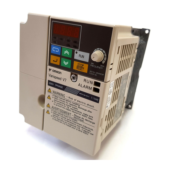
Varispeed V7
INSTRUCTION MANUAL
COMPACT GENERAL-PURPOSE INVERTER
(VOLTAGE VECTOR CONTROL)
FOR DeviceNet COMMUNICATIONS
Upon receipt of the product and prior to initial operation, read these instructions
thoroughly and retain them for future reference.
YASKAWA
YASKAWA
MANUAL NO. TOE-S606-13C
Advertisement
Chapters
Table of Contents

Subscribe to Our Youtube Channel
Related Manuals for YASKAWA Varispeed V7


Summary of Contents for YASKAWA Varispeed V7
- Page 1 YASKAWA Varispeed V7 INSTRUCTION MANUAL COMPACT GENERAL-PURPOSE INVERTER (VOLTAGE VECTOR CONTROL) FOR DeviceNet COMMUNICATIONS Upon receipt of the product and prior to initial operation, read these instructions thoroughly and retain them for future reference. YASKAWA MANUAL NO. TOE-S606-13C...
- Page 2 PREFACE Yaskawa’s Varispeed V7 is a small and simple Inverter; as easy to use as a contactor. This instruction manual describes installation, maintenance, inspection, troubleshooting, and specifications of the Varispeed V7. Read this instruction manual thoroughly before operation. YASKAWA ELECTRIC CORPORATION General Precautions •...
- Page 3 NOTATION FOR SAFETY PRECAUTIONS Read this instruction manual thoroughly before installation, operation, mainte- nance, or inspection of the Varispeed V7. In this manual, safety precautions are classified as either warnings or cautions and are indicated as shown below. WARNING Indicates a potentially hazardous situation which, if not avoided, may result in death or serious injury.
- Page 4 PRECAUTIONS FOR UL/cUL MARKING • Do not connect or disconnect wiring, or perform signal checks while the power supply is turned ON. • The Inverter internal capacitor is still charged even after the power supply is turned OFF. To prevent electric shock, disconnect all power before ser- vicing the Inverter, and then wait at least one minute after the power sup- ply is disconnected.
- Page 5 (open chassis type), or below 40°C (105°F) for NEMA 1 (TYPE 1), IP20 (top closed type). Overheating may cause a fire or damage the Inverter. • The Varispeed V7 generates heat. For effective cooling, mount it vertically. Refer to the figure in Mounting Dimensions on...
-
Page 6: Table Of Contents
WIRING WARNING (Ref. page) • Only begin wiring after verifying that the power supply is turned OFF. Failure to observe this warning may result in an elec- tric shock or a fire. • Wiring should be performed only by qualified personnel. -
Page 7: (Ref. Page)
CAUTION (Ref. page) • Verify that the Inverter rated voltage coincides with the AC power supply voltage. Failure to observe this caution may result in personal injury or a fire. • Do not perform a withstand voltage test on the Inverter. -
Page 8: Failure To Observe This Warning May Result In An Elec
OPERATION WARNING (Ref. page) • Only turn ON the input power supply after con- firming that the Digital Operator or blank cover (optional) are in place. Do not remove the Digital Operator, remove the covers, or set rotary switches while current is flowing. Failure to observe this warning may result in an elec- tric shock. -
Page 9: The Wiring For The Control Circuit Unless The Multi
WARNING (Ref. page) • If an alarm is reset with the operation signal ON, the Inverter will restart automatically. Reset an alarm only after verifying that the operation sig- nal is OFF. Failure to observe this warning may result in injury. •... - Page 10 If the indicators are not OFF, the capacitors are still charged and can be dangerous. • Do not perform withstand voltage test on any part of the Varispeed V7. The Inverter is an electronic device that uses semi- conductors, and is thus vulnerable to high voltage.
- Page 11 CAUTION (Ref. page) • The control PCB employs CMOS ICs. Do not touch the CMOS elements. They are easily damaged by static electricity. • Do not connect or disconnect wires, connectors, or the cooling fan while power is applied to the circuit.
- Page 12 WARNING LABEL A warning label is provided on the front cover of the Inverter, as shown below. Follow the warnings when handling the Inverter. Plastic Case Status Indicators Nameplate Warning Label Location International Certification Marks...
- Page 13 Warning Labels at End of Instruction Manual An English warning label is attached when the English Varispeed V7 is shipped. If a Japanese or French label is required, attach the warning label at the end of the Instruction Manual over the Japanese warning label.
- Page 14 Repairs If a Yaskawa product is found to be defective due to Yaskawa workman- ship or materials and the defect occurs during the warranty period, Yaskawa will provide a replacement, repair the defective product, and provide shipping to and from the site free of charge.
- Page 15 NOT covered by this warranty. RESTRICTIONS • The Varispeed V7 was not designed or manufactured for use in devices or systems that may directly affect or threaten human lives or health. • Customers who intend to use the product described in this manual for...
- Page 16 CONTENTS NOTATION FOR SAFETY PRECAUTIONS - - - - - - 2 1. Receiving the Product - - - - - - - - - - - - - - - - - - - 19 ■ Checking the Nameplate - - - - - - - - - - - - - - - - - - - - - - - - - - - 20 2.
- Page 17 Rotary Switches - - - - - - - - - - - - - - - - - - - - - - - - - - - - - - - - - 56 ■ Description of the DeviceNet Functions - - - - - - - - - - - - - - - - - 57 Initial Settings - - - - - - - - - - - - - - - - - - - - - - - - - - - - - - - - - - - 57 I/O Message Communications - - - - - - - - - - - - - - - - - - - - - - - 59 Explicit Message Communications - - - - - - - - - - - - - - - - - - - - 94...
- Page 18 Using Two Acceleration/Deceleration Times - - - - - - - - - - - - 143 Momentary Power Loss Ridethrough Method (n081) - - - - - - 144 S-curve Selection (n023) - - - - - - - - - - - - - - - - - - - - - - - - - - 145 Torque Detection - - - - - - - - - - - - - - - - - - - - - - - - - - - - - - - 146 Frequency Detection Level (n095) - - - - - - - - - - - - - - - - - - - 147 Jump Frequencies (n083 to n086) - - - - - - - - - - - - - - - - - - - 148...
- Page 19 COPY Function - - - - - - - - - - - - - - - - - - - - - - - - - - - - - - - - - 189 VERIFY Function- - - - - - - - - - - - - - - - - - - - - - - - - - - - - - - - 190 Inverter Capacity Display - - - - - - - - - - - - - - - - - - - - - - - - - - 192 Software No.
- Page 20 • Verify that the model number matches your purchase order or packing slip. • Check the Inverter for physical damage that may have occurred during shipping. If any part of Varispeed V7 is missing or damaged, call for service immedi- ately.
- Page 21 With Digital Operator (without potentiometer) 3.7 kW 3.7 kW Without Digital Operator 5.5 kW 5.5 kW 7.5 kW 7.5 kW Note: Contact your Yaskawa representatives for models without heatsinks. Voltage Class Single-phase 200 VAC Three-phase 200 VAC Three-phase 400 VAC Specifications Specifications...
- Page 22 2. Identifying the Parts 2. Identifying the Parts Digital Operator Terminal Cover DeviceNet Communi- cations Cable Hole Opening for Control Front Cover Circuit Wiring Opening for Main Nameplate Circuit Wiring Ground Terminal Heatsink Cooling Fan Bottom Cover Cooling Fan Cover Ground wire connecting DeviceNet communications cable’s shield to ground terminal Note: The wire connects the shield to the...
- Page 23 Varispeed V7 Inverters with the Covers Removed Frequency Setting Potentiometer Inverter Operation Baud Rate Setting Switch Status Indicators MAC ID Setting Switches Input Polarity Switch Jumper Bar Control Circuit Terminal Block Main Circuit Terminal Block DeviceNet Terminal Block Ground Terminals Example for 3-phase (200 V Class, 1.5 kW) Inverter...
- Page 24 2. Identifying the Parts Main Circuit Terminal Arrangement The terminal arrangement of the main circuit terminals depends on the Inverter model. CIMR-V7 20P1 to 20P7, B0P1 to B0P4 CIMR-V7 21P5, 22P2, B0P7, B1P5, 40P2 to 42P2 CIMR-V7 24P0, B2P2, 43P0, 43P7 CIMR-V7 B3P7 CIMR-V7...
- Page 25 3. Mounting Choosing a Location to Mount the Inverter Be sure the Inverter is protected from the following conditions. • Extreme cold and heat. Use only within the specified ambient tem- perature range: −10 to 50°C (14 to 122°F) for IP20 (open chassis type), −10 to 40°C (14 to 105°F) for NEMA 11 (TYPE 1), IP 20 (top closed type) •...
- Page 26 3. Mounting Mounting Dimensions To mount the Varispeed V7, the dimensions shown below are required. 100 mm (3.94 in.) min. 100 mm (3.94 in.) min. Voltage Class Max. Applicable Distance “a” Motor Capacity 200 V, Single phase 3.7 kW max.
- Page 27 • The dimensions shown for the distances on the left/right IMPORTANT and top/bottom of the Inverter apply to both mounting within a panel (IP00 and IP20) and enclosed models (NEMA1). • When operating a 5.5-kW or 7.5-kW Inverter (200 V or 400 V Class) within a panel, always remove the top and bottom covers.
- Page 28 3. Mounting • Removing the Digital Operator After removing the front cover, lift the upper and lower sides (section A) of the right side of the Digital Operator in direction • Mounting the Digital Operator Mount the Digital Operator by reversing the order of the above procedure for removal.
- Page 29 4. Wiring • Only begin wiring after verifying that the power sup- WARNING ply is turned OFF. Failure to observe this warning may result in an electric shock or a fire. • Wiring should be performed only by qualified per- sonnel.
- Page 30 4. Wiring emergency stop by using the external terminals. Delayed response may cause injury or damage the machine. Wiring Instructions 1. Always connect the power supply for the main circuit inputs to the power input terminals R/L1, S/L2, and T/L3 (R/L1, S/L2 for single- phase power) via a molded-case circuit breaker (MCCB) or a fuse.
- Page 31 5. Voltage drop should be considered when determining the wire size. Voltage drop can be calculated using the following equation: Phase-to-phase voltage drop (V) × wire resistance (Ω/km) × wiring distance (m) × current (A) × 10 Select a wire size so that voltage drop will be less than 2% of the normal rated voltage.
- Page 32 4. Wiring 3. Main Circuits 200 V Class 3-phase Input Inverters Model Terminal Symbols Screws Tighten- Wires Torque Applicable Size Recommended Type N•m Size (lb•in) CIMR- R/L1, S/L2, T/L3, M3.5 0.8 to 0.75 18 to 600 V V7∗∗ -, +1, +2, B1, B2, 1.0 (7.1 to 2 vinyl-...
- Page 33 200 V Class Single-phase Input Inverters Model Terminal Sym- Screws Tighten- Wires bols Torque Applicable Size Recommended Type N•m Size (lb•in) CIMR- R/L1, S/L2, T/L3, M3.5 0.8 to 0.75 to 18 to 600 V V7∗∗ -, +1, +2, B1, B2, 1.0 (7.1 vinyl- B0P1...
- Page 34 4. Wiring Model Terminal Sym- Screws Tighten- Wires bols Torque Applicable Size Recommended Type N•m Size (lb•in) CIMR- R/L1, S/L2, T/L3, 5.5 to 10 to 8 600 V V7∗A -, +1, +2, B1, B2, vinyl- 25P5 U/T1, V/T2, W/T3 sheathed wire or equivalent CIMR-...
- Page 35 400 V Class 3-phase Input Inverters Model Terminal Symbols Screws Tighten- Wires Torque Applicable Size Recommended Type N•m Size (lb•in) CIMR- R/L1, S/L2, T/L3, 1.2 to 2 to 14 to 600 V V7∗∗ -, +1, +2, B1, B2, vinyl- 40P2 U/T1, V/T2, W/T3 (10.65 sheathed...
- Page 36 4. Wiring Model Terminal Symbols Screws Tighten- Wires Torque Applicable Size Recommended Type N•m Size (lb•in) CIMR- R/L1, S/L2, T/L3, 5.5 to 10 to 8 600 V V7∗A -, +1, +2, B1, B2, vinyl- 47P5 U/T1, V/T2, W/T3 sheathed wire or equivalent Note: The wire size is given for copper wire at 75°C (160°F).
- Page 37 Never ground the Varispeed V7 to the same ground as welding machines, motors, or other electrical equipment. When several Varispeed V7 Inverters are used side by side, ground each as shown in exam- ples. Do not loop the ground wires.
- Page 38 4. Wiring • Braking Resistor Connection (Optional) To connect the braking resistor, cut the protector on terminals WARNING B1 and B2. To protect the braking resistor from overheating, install a ther- mal overload relay between the braking resistor and the Inverter.
- Page 39 Wiring the Control Circuits Pass the cable through wiring hole to connect it. Always mount the cover in its original position. S2 can be changed according to sequence input signal (S1 to S7) polar- ity. 0 V common: NPN side (Factory setting) +24 V common: PNP side Refer to pages 234 and 235 for S2.
- Page 40 4. Wiring Wiring the DeviceNet Communications Cable Use the following procedure to wire the DeviceNet communications cable to the terminal block (CN6). 1. Use a thin slotted screwdriver to loosen the terminal screws. 2. Insert the power supply wires into the terminal block from below. 3.
- Page 41 * 3. Route the DeviceNet communications cables separately from the main circuit wiring and other power lines. * 4. There is a 5.5-mm scale on the front of the Inverter just above the terminal block. Use this 5.5-mm scale to confirm the length of exposed wire when stripping wires.
- Page 42 5. Operating the Inverter 5. Operating the Inverter The Control Mode Selection (n002) is initially set to V/f control mode. • Only turn ON the input power supply after confirm- WARNING ing that the Digital Operator or blank cover (optional) are in place. Do not remove the Digital Operator or the covers while current is flowing.
- Page 43 Prior to shipping, the Inverter is set up to receive the RUN command and frequency reference from the Operator. Below are instructions for running the Varispeed V7 using the JVOP-147 Digital Operator (with- out potentiometer). For instructions on operation, refer to page 53.
- Page 44 5. Operating the Inverter Operation Steps Operator Function Status Indi- Display Indicators cators 1. Turn the potentiometer fully counter- clockwise, and then turn the power 2. F/R will flash. Select FWD or REV RUN using the keys. Never select REV when reverse run is prohibited.
- Page 45 Operating the Digital Operator All functions of the Varispeed V7 are set using the Digital Operator. Below are descriptions of the display and keypad sections. JVOP-140 Digital Operator Data display section Indicator/display section Function indicators Indicators switch to another function each time is pressed.
- Page 46 5. Operating the Inverter Description of Status Indicators The following diagram shows the positions of four status indicators (two Inverter operation status indicators, two DeviceNet communica- tions status indicators). The combinations of these indicators indicate the status of the Inverter and DeviceNet communications (On, flashing, and OFF).
- Page 47 DeviceNet Communications Status Indicators These indicators show the status of DeviceNet communications. Name Indication Operating Status Remarks Color Status Green Inverter communica- The Inverter is operat- tions operating ing normally. Green Flashing Inverter communica- There is an incorrect tions initializing baud rate setting or there is a MAC ID du- plication.
- Page 48 The following flowchart describes each function indicator. Power ON Frequency reference setting/monitoring (r/min) Sets Varispeed V7 operating speed. Output frequency monitoring (r/min) Displays frequency that Varispeed V7 is If the Varispeed V7 currently outputting loses power while in Setting disabled. one of these modes,...
- Page 49 LOCAL/REMOTE Selection This function switches the operation; operation using the digital operator including frequency setting with potentiometer, operation using the input terminals, or operation through communications Setting can be changed using the key. (Local) (Remote) Constant No./data Sets and changes data for a constant No. (Refer to page 52.) Return to MNTR Multi-function Monitoring...
- Page 50 5. Operating the Inverter Monitoring The following items can be monitored using U constants. Constant Name Unit Description U-01 Frequency Reference Frequency reference can be monitored. (Same as FREF) (FREF)* U-02 Output Frequency Output frequency can be monitored. (Same as FOUT) (FOUT)* U-03 Output current can be monitored.
- Page 51 Constant Name Unit Description U-61 DeviceNet consumed Connec- 20: Basic I/O Instance, Command tion Path (Connection Path Dur- 21: Extended I/O Instance, Command ing Operation) 100: MEMOBUS I/O Instance, Command 101: V7N Control I/O Instance, Command 102: Acceleration/Deceleration Time Control I/O In- stance, Command 105: Extended MEMOBUS I/O Instance, Command 106: General-purpose DI/DO Control I/O Instance,...
- Page 52 5. Operating the Inverter Input/Output Terminal Status Input terminal status 1: Terminal S1 is closed. 1: Terminal S2 is closed. 1: Terminal S3 is closed. (see note 1.) 1: Terminal S4 is closed. (see note 1.) 1: Terminal S5 is closed. (see note 2.) 1: Terminal S6 is closed.
- Page 53 Fault History Display Method When U-09 is selected, a four-digit box is displayed. The three digits from the right show the fault description, and the digit on the left shows the order of fault (from one to four). Number 1 represents the most recent fault, and numbers 2, 3, 4 represent the other faults, in ascending order of fault occurrence.
- Page 54 Digital setting (refer to 5. Operating the Inverter) and potentiometer setting are both possible for simple acceleration/deceleration operation of the Varispeed V7. DeviceNet communications are set to enabled at the factory (n004=9). Simple Operation from the Digital Operator Using Frequency...
- Page 55 Operation Steps Opera- Function Status Indicators tor Dis- Indicators play 1. Turn ON the power supply. 2. Set constant n004 to 1. (Enables the potentiometer and RUN/STOP commands from the Digital Operator.) 15.0 3. Set the following constants. n019: 15.0 (Acceleration Time) n020: 5.0 (Deceleration Time) (For- ward)
- Page 56 6. Operating with DeviceNet Communications 6. Operating with DeviceNet Communications Varispeed V7 Inverters can be connected to a DeviceNet network to com- municate with a DeviceNet master. The DeviceNet master can be used for various operations, such as sending RUN/STOP commands, monitoring run status, and setting/referencing of constants.
- Page 57 Item Specifications Explicit Message Up to 32 bytes of data can be transferred in Communications conformance with the DeviceNet AC/DC drive profile. Communications 11 to 25 VDC (20 mA max.) Power Supply Component Names and Settings Rotary Switches The rotary switches are used to set the DeviceNet baud rate and MAC ID (node address).
- Page 58 6. Operating with DeviceNet Communications Description of the DeviceNet Functions DeviceNet-compatible Inverters support the AC Drive Profile defined in DeviceNet specifications. No special settings are needed to operate, adjust, and monitor the Inverters from any DeviceNet master. DeviceNet-compatible Inverters operate as Group 2 Only servers (DeviceNet slaves) in the DeviceNet network.
- Page 59 Constant Name Description n004 Frequency 0: Enables the Digital Operator’s Reference potentiometer setting. Selection 1: Enables Frequency Reference 1 (constant n024). 7: Enables a voltage reference (0 to 10 V) at the Digital Operator’s cir- cuit terminal. 8: Enables a current reference (4 to 20 mA) at the Digital Operator’s circuit terminal.
- Page 60 6. Operating with DeviceNet Communications I/O Message Communications The DeviceNet-compatible Inverters use poll command/response mes- sages for I/O message communications. Select one of the seven sup- ported I/O instances and transfer I/O data with the master. I/O messages are always transferred between the Inverter and master at the fixed com- munications period whether or not there have been changes to the I/O data.
- Page 61 Data Name Contents Bytes Speed Sets the Inverter’s speed reference. 2 and 3 Reference Speed reference data: Frequency reference (r/min) × 2 : Speed scale Setting range: 0 to FFFF Hex For example, when setting a reference of 1,800 r/min with a speed scale of 0: Speed reference data = 1,800 ×...
- Page 62 6. Operating with DeviceNet Communications Data Name Contents Byte 0, Running 1 Indicates the Inverter’s operating status. bit 2 (Fwd) 0: Stopped, operating in reverse, or applying DC injection braking (Reverse RUN command ON). 1: Operating forward or applying DC injection braking (Reverse RUN com- mand OFF).
- Page 63 Data Name Contents Byte 0, Run Fwd Runs the Inverter forward. bit 0 0: Stop. 1: Run forward. Byte 0, Run Rev Runs the Inverter in reverse. bit 1 0: Stop. 1: Run in reverse. Byte 0, Fault Reset Resets the Inverter from fault status. bit 2 0: --- 1: Reset fault.
- Page 64 6. Operating with DeviceNet Communications Byte Bit 7 Bit 6 Bit 5 Bit 4 Bit 3 Bit 2 Bit 1 Bit 0 Speed Actual (High Byte) Data Name Contents Byte 0, Faulted Indicates that the Inverter detected a bit 0 fault.
- Page 65 MEMOBUS I/O Instances All of the Inverter’s constants can be referenced and set with a MEMOBUS I/O instance. MEMOBUS I/O instances can be used with Yaskawa Inverters only. They cannot be used with other companies’ DeviceNet-compatible Inverters. Five bytes are used for input data and five bytes are used for output data.
- Page 66 6. Operating with DeviceNet Communications • Input (Master → Inverter) Instance 100 (64 Hex) Byte Bit 7 Bit 6 Bit 5 Bit 4 Bit 3 Bit 2 Bit 1 Bit 0 Function Code Register Number (High Byte) Register Number (Low Byte) Register Data (High Byte) Register Data (Low Byte) Data...
- Page 67 All of the Inverter’s I/O functions can be used in addition to the functions supported by the Extended I/O Instances. V7 Standard control I/O instances can be used with Yaskawa Inverters only. They cannot be used with other companies’ DeviceNet-compati- ble Inverters.
- Page 68 6. Operating with DeviceNet Communications Byte Bit 7 Bit 6 Bit 5 Bit 4 Bit 3 Bit 2 Bit 1 Bit 0 Speed Reference (High Byte) Data Name Contents Byte 0, Run Fwd Runs the Inverter forward. bit 0 0: Stop. 1: Run forward.
- Page 69 Data Name Contents Byte 0, Terminal Inputs the function set for Inverter con- bit 5 stant n055 (Multi-function Input Selec- tion 6.) 0: Terminal S6 function OFF 1: Terminal S6 function ON Byte 0, Terminal Inputs the function set for Inverter con- bit 6 stant n056 (Multi-function Input Selec- tion 7.)
- Page 70 6. Operating with DeviceNet Communications Data Name Contents Byte 1, Terminal Operates the Inverter’s multi-function bit 7 output terminal P2. This function is en- abled only when Inverter constant n059 is set to 18. 0: Terminal P2 OFF 1: Terminal P2 ON Bytes Speed Sets the Inverter’s speed reference.
- Page 71 Data Name Contents Byte 0, Running Indicates the Inverter’s operating status. bit 0 0: Stopped. 1: Operating forward, operating in reverse, or applying DC injection braking. Byte 0, Indicates the Inverter’s operating status. bit 1 0: Operating forward or in reverse. 1: Stopped or applying DC injection braking.
- Page 72 6. Operating with DeviceNet Communications Data Name Contents Byte 0, Warning Indicates that the Inverter detected a bit 6 warning. 0: Normal 1: Warning detected. Byte 0, Faulted Indicates that the Inverter detected a bit 7 fault. 0: Normal 1: Fault detected. Byte 1, Indicates that the Inverter detected a bit 0...
- Page 73 Data Name Contents Byte 1, Terminal Indicates the output status of Inverter bit 5 multi-function output terminal P2. 0: Terminal P2 OFF 1: Terminal P2 ON Bytes Speed Ac- Indicates the Inverter’s speed. 2 and 3 tual The units depend on the setting in Invert- er constant n035.
- Page 74 6. Operating with DeviceNet Communications • Input (Master → Inverter) Instance 102 (66 Hex) Byte Bit 7 Bit 6 Bit 5 Bit 4 Bit 3 Bit 2 Bit 1 Bit 0 Termi- Termi- Termi- Termi- Termi- nal S7* nal S6* nal S5* nal S4 nal S3...
- Page 75 Data Name Contents Byte 0, Terminal Inputs the function set for the Inverter’s bit 3 multi-function input terminal S4. Set the function of multi-function input terminal S4 with Inverter constant n053. 0: Terminal S4 function OFF 1: Terminal S4 function ON Byte 0, Terminal Inputs the function set for Inverter con-...
- Page 76 6. Operating with DeviceNet Communications Data Name Contents Byte 1, Terminal Operates the Inverter’s multi-function bit 5 output terminal MA. This function is en- abled only when Inverter constant n057 is set to 18. 0: Terminal MA OFF 1: Terminal MA ON Byte 1, Terminal Operates the Inverter’s multi-function...
- Page 77 Data Name Contents Bytes Decelera- Sets the Inverter’s deceleration time. 6 and 7 tion Time 1 The units depend on the setting in Inverter constant n018. (The factory set- ting is for units of 0.1 s.) The value set here is recorded in EEPROM. The units are not affected by the time scale (TS) setting.
- Page 78 6. Operating with DeviceNet Communications Data Name Contents Byte 0, Indicates the Inverter’s operating status. bit 1 0: Operating forward or in reverse. 1: Stopped or applying DC injection braking. Byte 0, Rev Run- Indicates the Inverter’s operating status. bit 2 ning 0: Operating forward, stopped (Reverse RUN command OFF), or applying DC...
- Page 79 Data Name Contents Byte 0, Faulted Indicates that the Inverter detected a bit 7 fault. 0: Normal 1: Fault detected. Byte 1, Indicates that the Inverter detected a bit 0 MEMOBUS constant setting error (OPE). 0: Normal 1: OPE (OP1 to OP5) detected. Byte 1, Indicates that the Inverter detected an bit 1...
- Page 80 Extended MEMOBUS I/O Instances Extended MEMOBUS I/O Instances are for DeviceNet-compatible Inverters only. Extended MEMOBUS I/O Instances can be used with Yaskawa Invert- ers only. They cannot be used with other companies’ DeviceNet-com- patible Inverters. Eight bytes are used for input data and eight bytes are used for output data.
- Page 81 Byte Bit 7 Bit 6 Bit 5 Bit 4 Bit 3 Bit 2 Bit 1 Bit 0 Register Number (Low Byte) Register Number (High Byte) Register Data (Low Byte) Register Data (High Byte) Data Name Contents Byte 0, Run Fwd Runs the Inverter forward.
- Page 82 6. Operating with DeviceNet Communications Data Name Contents Byte 0, Terminal Inputs the function set for Inverter con- bit 5 stant n055 (Multi-function Input Selec- tion 6.) 0: Terminal S6 function OFF 1: Terminal S6 function ON Byte 0, Terminal Inputs the function set for Inverter con- bit 6 stant n056 (Multi-function Input Selec-...
- Page 83 Data Name Contents Byte 1, Terminal Operates the Inverter’s multi-function bit 6 output terminal P1. This function is en- abled only when Inverter constant n058 is set to 18. 0: Terminal P1 OFF 1: Terminal P1 ON Byte 1, Terminal Operates the Inverter’s multi-function bit 7 output terminal P2.
- Page 84 6. Operating with DeviceNet Communications Status of Func- Status of Func- Function tion Code 1 tion Code 2 (Byte 1, bit 1) (Byte 1, bit 2) Fnc. Code 1 = 1 Fnc. Code 2 = 0 The data specified in bytes 6 and 7 will be writ- ten to the register speci- fied in bytes 4 and 5.
- Page 85 Data Name Contents Byte 0, Indicates the Inverter’s operating status. bit 1 0: Operating forward or in reverse. 1: Stopped or applying DC injection braking. Byte 0, Rev Run- Indicates the Inverter’s operating status. bit 2 ning 0: Operating forward, stopped (Reverse RUN command OFF), or applying DC injection braking (Reverse RUN com- mand OFF).
- Page 86 6. Operating with DeviceNet Communications Data Name Contents Byte 0, Faulted Indicates that the Inverter detected a bit 7 fault. 0: Normal 1: Fault detected. Byte 1, Indicates that the Inverter detected a bit 0 MEMOBUS constant setting error (OPE). 0: Normal 1: OPE (OP1 to OP5) detected.
- Page 87 Data Name Contents Byte 1, Terminal Indicates the output status of Inverter bit 7 multi-function output terminal P2. 0: Terminal P2 OFF 1: Terminal P2 ON Bytes Speed Ac- Indicates the Inverter’s speed. 2 and 3 tual The units depend on the setting in Invert- er constant n035.
- Page 88 ENTER Command (Write-only Register) on page 126 for details. General-purpose DI/DO Control I/O Instances can be used with Yaskawa Inverters only. They cannot be used with other companies’ DeviceNet-compatible Inverters. Eight bytes are used for input data and eight bytes are used for output data.
- Page 89 Byte Bit 7 Bit 6 Bit 5 Bit 4 Bit 3 Bit 2 Bit 1 Bit 0 Speed Reference (High Byte) Not used. Not used. Not used. Not used. Data Name Contents Byte 0, Run Fwd Runs the Inverter forward. bit 0 0: Stop.
- Page 90 6. Operating with DeviceNet Communications Data Name Contents Byte 0, Terminal Inputs the function set for Inverter con- bit 5 stant n055 (Multi-function Input Selec- tion 6.) 0: Terminal S6 function OFF 1: Terminal S6 function ON Byte 0, Terminal Inputs the function set for Inverter con- bit 6 stant n056 (Multi-function Input Selec-...
- Page 91 Data Name Contents Byte 1, Terminal Operates the Inverter’s multi-function bit 7 output terminal P2. This function is en- abled only when Inverter constant n059 is set to 18. 0: Terminal P2 OFF 1: Terminal P2 ON Bytes Speed Indicates the Inverter’s speed reference. 2 and 3 Reference The units depend on the setting in...
- Page 92 6. Operating with DeviceNet Communications Data Name Contents Byte 0, Running Indicates the Inverter’s operating status. bit 0 0: Stopped. 1: Operating forward, operating in reverse, or applying DC injection braking. Byte 0, Indicates the Inverter’s operating status. bit 1 0: Operating forward or in reverse.
- Page 93 Data Name Contents Byte 0, Warning Indicates that the Inverter detected a bit 6 warning. 0: Normal 1: Warning detected. Byte 0, Faulted Indicates that the Inverter detected a bit 7 fault. 0: Normal 1: Fault detected. Byte 1, Terminal Indicates the input status of Inverter bit 0 multi-function input terminal S1.
- Page 94 6. Operating with DeviceNet Communications Data Name Contents Byte 1, Terminal Indicates the input status of Inverter bit 3 multi-function input terminal S4. When using this terminal as a general-purpose DI terminal, always set Inverter constant n053 to 28. 0: Terminal S4 OFF 1: Terminal S4 ON Byte 1, Terminal...
- Page 95 Explicit Message Communications The DeviceNet-compatible Inverters can transfer explicit messages (defined in DeviceNet specifications) to and from a DeviceNet master. Various kinds of data can be set and referenced from the master, ranging from DeviceNet-related settings to the Inverter’s control data. Unlike I/ O message communications, which are performed at regular intervals, the explicit messages can be sent from the master at any time and corre- sponding response messages will be returned.
- Page 96 Revision Vendor Indicates the man- 002C Word ufacturer's code. • 44 (2C Hex): Yaskawa Elec- tric Device Indicates the De- 0002 Word Type viceNet device profile. This prod- uct implements the AC Drive pro- file.
- Page 97 Name Contents Setting Factory Set- Read Write Size stance tribute Range ting (Hex) Status Indicates the 0001 Word Inverter's commu- nications status. Serial Indicates the seri- Depends Long Number al number of the on prod- Inverter communi- uct. cations. Product Indicates the mod- Capacity String...
- Page 98 6. Operating with DeviceNet Communications • Object Contents Name Contents Setting Factory Set- Read Write Size stance tribute Range ting (Hex) Object Indicates the Mes- 0001 Word Soft- sage Router ob- ware ject's software Revision revision. DeviceNet Object (Class 03 Hex) The DeviceNet object is the object that manages information and func- tions related to DeviceNet communications.
- Page 99 Name Contents Setting Factory Set- Read Write Size stance tribute Range ting (Hex) MAC ID Indicates the set- 0 to Byte ting for the MAC ID. The MAC ID can be set with the rotary switches or constant n150. Baud Indicates the set- 0 to 2 Byte...
- Page 100 6. Operating with DeviceNet Communications • Object Contents Name Contents Setting Factory Set- Read Write Size stance tribute Range ting (Hex) Object Indicates the As- 0002 Word Soft- sembly object's ware software revision. Revision Data This function is Byte x the same as the note 1.
- Page 101 * 2. When I/O message communications are enabled, the data set here will be overwritten by the I/O message data. Do not use this object when I/O message communications are enabled. DeviceNet Connection Object (Class 05 Hex) The DeviceNet object is the object that manages information and func- tions related to DeviceNet communications connections.
- Page 102 6. Operating with DeviceNet Communications Name Contents Setting Factory Set- Read Write Size stance tribute Range ting (Hex) Pro- Indicates the label Word duced that is used in the connec- Inverter’s commu- tion ID nications header. These values are set when the com- Con- Word munications con-...
- Page 103 Name Contents Setting Factory Set- Read Write Size stance tribute Range ting (Hex) Con- Indicates the appli- Array sumed cation object that connec- receives data from tion path the instance. State Indicates the in- Byte stance status. 00: Does not exist in network or ini- tializing.
- Page 104 6. Operating with DeviceNet Communications Name Contents Setting Factory Set- Read Write Size stance tribute Range ting (Hex) Watch- Indicates the ac- Byte dog tim- tion to take when a eout timeout occurred action during internal pro- cessing related to communications.
- Page 105 • Object Contents Name Contents Setting Factory Set- Read Write Size stance tribute Range ting (Hex) Object Indicates the Mo- 0001 Word Soft- tor Data object's ware software revision. Revision Motor Indicates the type Byte Type of motor being used. 7: Squirrel-cage induction motor Rated...
- Page 106 6. Operating with DeviceNet Communications Service Service Name Description Code (Hex) Set_Attribute_ Changes the contents of the speci- Single fied attribute. Reset Resets the Inverter. • Object Contents Name Contents Setting Factory Set- Read Write Size stance tribute Range ting (Hex) Object Indicates the Con- 0001...
- Page 107 Name Contents Setting Factory Set- Read Write Size stance tribute Range ting (Hex) Running Indicates the Byte Inverter’s operat- ing status. 00: Stopped, oper- ating in reverse, or applying DC injec- tion braking (Re- verse RUN command ON). 01: Operating for- ward or applying DC injection brak- ing (Reverse RUN...
- Page 108 6. Operating with DeviceNet Communications Name Contents Setting Factory Set- Read Write Size stance tribute Range ting (Hex) Ctrl Indicates which Byte From RUN command in- put has been se- lected in the Inverter. 00: A RUN com- mand input other than DeviceNet is enabled.
- Page 109 DeviceNet Operator Meaning Fault Code Fault Dis- (Hex) play 2300 Overcurrent 2310 Motor overload 2330 Ground fault 2340 Load short-circuit 3130 Main circuit voltage fault Output open phase 3210 Main circuit overvoltage 3220 Main circuit undervoltage 4210 Heatsink overheating 5110 Control power supply error 5210 Inverter A/D converter fault...
- Page 110 6. Operating with DeviceNet Communications DeviceNet Operator Meaning Fault Code Fault Dis- (Hex) play 9000 Emergency stop External fault (input terminal S3) External fault (input terminal S4) External fault (input terminal S5) External fault (input terminal S6) External fault (input terminal S7) External fault from communications * 1.
- Page 111 DeviceNet Operator Meaning Fault Code Fault Dis- (Hex) play 5300 Operator not connected 7500 Inverter communications error 9000 External fault (input terminal S3) External fault (input terminal S4) External fault (input terminal S5)* External fault (input terminal S6)* External fault (input terminal S7)* External fault from communications * These faults are displayed only when they have been operated through DeviceNet communications.
- Page 112 6. Operating with DeviceNet Communications AC/DC Drive Object (Class 2A Hex) The AC/DC Drive object is the object that manages information and functions related to the Inverter operation. This object is used for opera- tions such as setting the speed reference, monitoring various values, and changing the settings.
- Page 113 Name Contents Setting Factory Set- Read Write Size stance tribute Range ting (Hex) NetRef Sets the Frequen- 00,01 Byte cy Reference right. (See note 1.) 00: Use the Fre- quency Reference input method set in constant n004 (Frequency Refer- ence Selection). 01: Enables the Frequency Refer- ence from De-...
- Page 114 6. Operating with DeviceNet Communications Name Contents Setting Factory Set- Read Write Size stance tribute Range ting (Hex) Input Indicates the 00C8 (200 Word Voltage Inverter’s input V) or 0190 voltage. (400 V) Minimum units: V/ : Voltage scale (attribute 1B) Output Indicates the 0000...
- Page 115 Name Contents Setting Factory Set- Read Write Size stance tribute Range ting (Hex) Speed Sets or references -15 to Byte Scale the unit coefficient (n153) for speed- (F1 to related data. Speed units: 1 (r/ min) x 1/2 : Speed scale setting Current Sets or references...
- Page 116 6. Operating with DeviceNet Communications * 2. Always set the Number of Motor Poles (2 to 39) in Inverter constant n035 when using the Speed Ref, Speed Actual, Low Spd Limit, or High Spd Limit settings. * 3. The Drive Mode, Low Spd Limit, and High Spd Limit settings cannot be changed while the Inverter is running.
- Page 117 Error Code Tables Explicit Message Communications Errors When there is a problem with a request message sent from the master in explicit communications, the Inverter will return a response message with 94 as the service code well as one of the following error codes as the data.
- Page 118 6. Operating with DeviceNet Communications Error Contents Cause Corrective Action Code 1FFF Vendor spe- • Attempted to • Stop the cific error change an Inverter. Inverter con- • Specify a value stant that can- that is within not be changed the setting while the range.
- Page 119 Error Contents Cause Code 21 Hex Data set- • A simple upper/lower limit error ting error occurred with control data or constant write operation. • A constant setting error occurred when a constant was written. 22 Hex Write-in • Attempted to write a constant from the mode error master while Inverter was running.
- Page 120 6. Operating with DeviceNet Communications MEMOBUS Register Tables Reference Data (Read/Write Registers) Write zeroes in the unused bits. Do not write any data in the reserved registers. Register Contents Number 0000H Reserved 0001H Operation signals RUN command 1: RUN 0: STOP Reverse RUN command 1: Reverse run 0: Stop...
- Page 121 Register Contents Number 0009H Output terminal status Multi-function output reference 1* (Enabled when n057 is set to 18.) 1: MA ON 0: MA OFF Multi-function output reference 2 (Enabled when n058 is set to 18.) 1: P1 ON 0: P1 OFF Multi-function output reference 3 (Enabled when n059 is set to 18.) 1: P2 ON...
-
Page 122: Register
6. Operating with DeviceNet Communications Monitor Data (Read-only Registers) Register Contents Number 0020H Status signals Forward run 1: Run 0: Stop Reverse run 1: Reverse run 0: Forward run Inverter ready for operation Fault Data setting error 1: Error Multi-function output 1 1: MA ON Multi-function output 2 1: P1 ON... - Page 123 Register Contents Number 0021H Fault contents Overcurrent (OC) Overvoltage (OV) Inverter overload (OL2) Inverter overheat (OH) Not used. Not used. PID feedback loss (FbL) External fault (EF, EF0), Emergency stop (STP) Hardware fault (F Motor overload (OL1) Overtorque detected (OL3) Not used.
- Page 124 6. Operating with DeviceNet Communications Register Contents Number 0023H Frequency reference (Units set in n035.) 0024H Output frequency (Units set in n035.) 0025H to Reserved 0027H 0028H Output voltage reference (1/1V) 0029H to Reserved 002AH 002BH Sequence input status Terminal S1 (1: Closed) Terminal S2 (1: Closed) Terminal S3 (1: Closed) Terminal S4 (1: Closed)
- Page 125 Register Contents Number 002CH Inverter status Run (1: Run) Zero-speed (1: Zero-speed) Frequency match (1: Match) Minor fault (Alarm indicated.) Frequency detection 1 (1: Output frequency ≤ setting in n095) Frequency detection 1 (1: Output frequency ≥ setting in n095) Inverter ready for operation (1: Ready) Undervoltage detection (1: Undervoltage being detected.)
- Page 126 6. Operating with DeviceNet Communications Register Contents Number 002DH Output status (1: Closed) P1 (1: Closed) P2 (1: Closed) Not used. Not used. Not used. Not used. Not used. 8 to F Not used. 002EH to Reserved. 0030H 0031H Main circuit DC voltage (1/1 V) 0032H Torque monitor (1/1%;...
- Page 127 ENTER Command (Write-only Register) Register Name Contents Setting Factory Number Range Setting 0900H ENTER Writes constant data 0000H Com- to non-volatile memo- mand ry (EEPROM). FFFFH When writing a constant from the master through communications, always execute the ENTER command after changing the constant. When a constant is changed, the new value is written to the constant data area in the Inverter’s RAM.
- Page 128 7. Programming Features 7. Programming Features Factory settings of the constants are shaded in the tables. Constant Setup and Initialization Constant Selection/Initialization (n001) The following table lists the data that can be set or read when n001 is set. Unused constants between n001 and n179 are not displayed. n001 Setting Constant That Can Be Constant That Can Be Refer-...
- Page 129 (n016) For details, refer to Adjusting Torque According to Appli- cation (V/f Pattern Setting) on page 129. 3. If the following conditions are not satisfied in the jump frequency settings: Jump Frequency 3 (n085) ≤ Jump Frequency 2 (n084) ≤ Jump Frequency 1 (n083) 4.
- Page 130 7. Programming Features Using V/f Control Mode V/f control mode is preset at the factory. Control Mode Selection (n002) = 0: V/f control mode (factory setting) 1: Vector control mode Adjusting Torque According to Application Adjust motor torque by using the V/f pattern and full-range automatic torque boost settings.
- Page 131 Typical Setting of the V/f Pattern Set the V/f pattern according to the application as described below. For 400-V Class Inverters, the voltage values (n012, n015, and n017) should be doubled. When running at a frequency exceeding 50/60 Hz, change the Maximum Output Frequency (n011). Note: Always set the maximum output frequency according to the motor char- acteristics.
- Page 132 The motor torque requirement changes according to load conditions. The full-range automatic torque boost adjusts the voltage of the V/f pat- tern according to requirements. The Varispeed V7 automatically adjusts the voltage during constant-speed operation, as well as during accelera- tion.
- Page 133 1: Vector control mode Precautions for Voltage Vector Control Application Vector control requires motor constants. The Yaskawa standard motor constants have been set at the factory prior to shipment. Therefore, when a motor designed for an Inverter is used or when a motor from any...
- Page 134 7. Programming Features • If the speed is more than the target value, reduce the slip compensa- tion gain. Adjustment of the Slip Compensation Time Constant (n112) is normally not required. Adjust it under the following conditions: • Reduce the setting if response is slow. •...
- Page 135 the motor test report. To connect a reactor between the Inverter and the motor, set n108 to the sum of the initial value of n108 (Motor Leakage Inductance) and the externally mounted reactor inductance. Unless a reactor is connected, n108 (Motor Leakage Inductance) does not have to be set according to the motor.
- Page 136 7. Programming Features When operating with frequency larger than 60/50 Hz, change only the Max. Output Frequency (n011). Constant output or Constant torque variable output n012 =200 V Base point n013 n011 =50 Hz =90 Hz Switching LOCAL/REMOTE Mode The following functions can be selected by switching LOCAL or REMOTE mode.
- Page 137 How to Select LOCAL/REMOTE Mode When LOCAL/REMOTE When LOCAL/REMOTE switching function is not switching function is set set for multi-function for multi-function input input selection selection (When 17 is not set (When 17 is set for for any of constants any of constants n050 to n056) n050 to n056)
- Page 138 7. Programming Features REMOTE Mode 1. Select remote mode. There are following two methods to select remote mode. • Select rE (remote mode) for the selection. • When the local/remote switching function is selected for the multi-function input selection, turn OFF the input terminal to select remote mode.
- Page 139 • Digital Setting Using the Digital Operator Input the frequency while FREF is lit (press ENTER after setting the numeric value). Frequency reference setting is effective when 1 (Factory setting: 0) is set for constant n009 instead of pressing ENTER. n009 =0: Enables frequency reference setting using the ENTER key.
- Page 140 7. Programming Features Setting Operation Conditions Reverse Run Prohibit (n006) The Reverse Run Prohibit setting disables accepting a reverse RUN command from the control circuit terminal or Digital Operator. This set- ting is used for applications where a reverse RUN command can cause problems.
- Page 141 (n031) 1800 r/min (n030) 1650 r/min (n029) 1500 r/min (n028) 1350 r/min (n027) 1200 r/min (n026) 1050 r/min (n025) 900 r/min Frequency (n024) 750 r/min reference Time FWD RUN/STOP Multi-step speed ref. 1 (terminal S2) Multi-step speed ref. 2 (terminal S3) Multi-step speed ref.
- Page 142 7. Programming Features Operating at Low Speed By inputting a JOG command and then a FORWARD (REVERSE) RUN command, operation is enabled at the jog frequency set in n032. When multi-step speed references 1, 2, 3 or 4 are input simultaneously with the JOG command, the JOG command has priority.
- Page 143 Typical Settings • To operate the Inverter with a frequency reference of 0% to 100% at an input voltage of 0 to 5 V Max. frequency (100%) Gain n068 = 200 Bias n069 = 0 • To operate the Inverter with a frequency reference of 50% to 100% at an input voltage of 0 to 10 V Max.
- Page 144 7. Programming Features Using Two Acceleration/Deceleration Times Decel Decel Time 1 Accel Time 2* Accel (n020) Time 2 (n022) Time 1 (n021) (n019) Decel Time 1* (n020) Time FORWARD (REVERSE) FUN command Multi-Step Speed Reference Accel/Decel Time Selection (Terminals S1 to S7) (See note.) * When deceleration to a stop is selected (n005 = 0).
- Page 145 n018 Settings Unit Setting Range n018 0.1 s 0.0 to 999.9 s (999.9 s or less) 1000 to 6000 s (1000 s or more) 0.01 s 0.00 to 99.99 s (99.99 s or less) 0.1 s 100.0 to 600.0 s (100 s or more) Note: Constant n018 can be set while stopped.
- Page 146 7. Programming Features * 1. Hold the operation signal to continue operation after recovery from a momentary power loss. * 2. When 2 is selected, the Inverter restarts if power supply voltage recovers while the control power supply is held. No fault signal is output.
- Page 147 Torque Detection If an excessive load is applied to the machine, an increase in the output current can be detected to output an alarm signal to multi-function out- put terminal MA, P1, or P2. To output an overtorque detection signal, set one of the output terminal function selections n057 to n059 for overtorque detection (Setting: 6 (NO contact) or 7 (NC contact)).
- Page 148 7. Programming Features Overtorque Detection Level (n098) Set the overtorque detection current level in units of 1%. (Inverter rated current = 100%) When detection by the output torque is selected, the motor rated torque becomes 100%. Factory setting: 160% Overtorque Detection Time (n099) If the time that the motor current exceeds the Overtorque Detection Level (n098) is longer than Overtorque Detection Time (n099), the overtorque detection function will operate.
- Page 149 Frequency Detection 2 Output frequency ≤ Frequency Detection Level n095 (Set n057, n058 or n059 to 5.) Release width Frequency +2Hz Detection Level (Hz) (n095) Output frequency Frequency detection signal Jump Frequencies (n083 to n086) This function allows the prohibition or “jumping” of critical frequencies so that the motor can operate without resonance caused by the machine system.
- Page 150 7. Programming Features The Inverter can be set to restart and reset fault detection after a fault occurs. The number of self-diagnosis and retry attempts can be set to up to 10 in n082. The Inverter will automatically restart after the following faults occur: OC (overcurrent) OV (overvoltage)
- Page 151 DC Injection Braking at Startup (n089, n091) Restarts a coasting motor after stopping it. Set the DC injection braking time at startup in n091 in units of 0.1 second. Set the DC Injection Brak- ing Current in n089 in units of 1% (Inverter rated current =100%). When the setting of n091 is 0, DC injection braking is not performed and acceleration starts from the minimum output frequency.
- Page 152 7. Programming Features Reducing Motor Noise or Leakage Current Using Carrier Fre- quency Selection (n080) Set the Inverter output transistor switching frequency (carrier fre- quency). Setting Carrier Frequency (kHz) Metallic Noise Noise and Cur- from Motor rent Leakage 12 fout (Hz) 24 fout (Hz) 36 fout (Hz) Higher...
- Page 153 If the set value is 7, 8, or 9, the carrier frequency will be multiplied by the same factor as the output frequency. n080=7 fc=Carrier frequency 2.5 kHz fc=12 fout 1.0 kHz fout=Output frequency 83.3 Hz 208.3 Hz n080=8 fc=Carrier frequency 2.5 kHz fc=24 fout 1.0 kHz...
- Page 154 7. Programming Features Voltage Capacity Factory Setting Maximum Reduced Class (V) (kW) Continuous Current Setting Carrier Fre- Output Cur- quency (kHz) rent (A) 400 V 0.37 3-phase 0.55 14.8 14.8 17.0 1. Reduce the continuous output current when changing the NOTE carrier frequency to 4 (10 kHz) for 200 V Class (1.5 kW or more) and 400 V Class Inverters.
- Page 155 4. The carrier frequency is automatically reduced to 2.5 kHz when the Reducing Carrier Frequency Selection at Low Speed (n175) is set to 1 and the following conditions are satisfied: Output frequency ≤ 5 Hz Output current ≥ 110% Factory setting: 0 (Disabled) 5.
- Page 156 7. Programming Features Selecting the Stopping Method Stopping Method Selection (n005) Select the stopping method suitable for the application. Setting Description Deceleration to a stop Coast to a stop Deceleration to a Stop Example when Acceleration/deceleration Time 1 is selected Deceleration Acceleration Min.
- Page 157 Coast to a Stop Example when Acceleration/deceleration Time 1 is selected Acceleration Time 1 Deceleration (n019) Time 1 Output Coast to (n020) frequency stop Time FWD (REV) RUN command * Changing the Frequency Reference while Running Upon termination of the FWD (REV) RUN command, the motor starts coasting.
-
Page 158: Reverse Run Command
7. Programming Features Building Interface Circuits with External Devices Using Input Signals The functions of multi-function input terminals S1 to S7 can be changed as necessary by setting constants n050 to n056. With the exception of the value “28,” the same value cannot be set for more than one of these constants. - Page 159 Setting Name Description Ref. SEARCH command from SPEED SEARCH command maximum frequency signal SEARCH command from set frequency ACCELERATION/ DECELERATION HOLD command LOCAL/REMOTE selection Communications/control cir- cuit terminal selection Emergency stop fault, Inverter stops for an emer- NO contact input gency stop signal input ac- cording to the Stopping Method Selection (n005).
-
Page 160: 1: Reverse Run
Terminal Functions for 3-wire Sequence Selection When 0 is set for terminal S3 (n052), terminal S1 is the RUN command, terminal S2 is the STOP command, and terminal S3 is the FWD/REV RUN command. Varispeed V7 RUN SW STOP SW (NO contact) - Page 161 LOCAL/REMOTE Selection (Setting: 17) Select the operation reference from either the Digital Operator or from the settings of the RUN Command Selection (n003) and Frequency Ref- erence Selection (n004). The LOCAL/REMOTE Selection can be used only when stopped. Open: Run according to the setting of RUN Command Selection (n003) or Frequency Reference Selection (n004).
- Page 162 7. Programming Features Time Chart for UP/DOWN Command Input FWD RUN UP command S3 DOWN command S4 Upper limit speed Lower limit speed output frequency FREQUENCY agree signal U = UP (accelerating) status D = DOWN (decelerating) status H = HOLD (constant speed) status U1 = UP status, clamping at upper limit speed D1 = DOWN status, clamping at lower limit speed Note: 1.
- Page 163 Setting Description Output frequency is not recorded during HOLD. When HOLD status is continued for 5 seconds or longer, the output frequency during HOLD is recorded and the Inverter restarts at the re- corded frequency. Communications/Multi-function Input Terminal Selection (Setting: 18) Operation can be changed from DeviceNet communications commands, or from multi-function input terminal or Digital Operator commands.
-
Page 164: Not Used
7. Programming Features n077 Settings Setting Function Description The multi-function input is dis- Disabled abled. When frequency reference 2 is se- Auxiliary frequency reference (FREF2) lected using the multi-step speed references, the input analog sig- nal for the CN2 terminal will be the frequency reference. - Page 165 Multi-function Analog Input Signal Selection (n078) Constant Name Unit Setting Range Factory Setting n078 Multi-function Analog 0=Digital Operator ter- Input Signal Selection minal (voltage: 0 to 10 V) 1=Digital Operator ter- minal (current 4 to 20 mA) Using Output Signals (n057, n058, n059) The functions of multi-function output terminals MA, P1 and P2 can be changed as necessary by setting constants n057, n058, and n059.
- Page 166 7. Programming Features Setting Name Description Ref. Low torque detected, NO output Low torque detected, NC output Minor fault Closed when an alarm has been detected. Baseblocked Closed when the Inverter output is OFF. Operating mode Closed when LOCAL is selected for the LOCAL/REMOTE selec- tion.
- Page 167 • FREQUENCY AGREE Signal (setting=2) Release width Detection width ±4 Hz ±2 Hz Output frequency FREQUENCY AGREE signal...
- Page 168 7. Programming Features Preventing the Motor from Stalling (Current Limit) This function automatically adjusts the output frequency and output cur- rent according to the load to continue operation without stalling the motor. Stall Prevention (Current Limit) Level during Acceleration (n093) Sets the stall prevention (current limit) level during acceleration in units of 1%.
- Page 169 In the constant output area (output frequency > Max. Voltage Output Frequency (n013)), the stall prevention (current limit) level during acceleration is automatically decreased using the following equa- tion. Stall prevention (current limit) level during acceleration in constant output area Max.
- Page 170 7. Programming Features ation Time 1 (n019) and Deceleration Time 1 (n020), or for Accelera- tion Time 2 (n021) and Deceleration Time 2 (n022). Motor current : Decreases frequency to prevent the motor from stalling. n094 : At start of acceleration, the output current hysterisis is approx.
- Page 171 Acceleration/Deceleration Time Selection during Stall Pre- vention (n116) With this function, Acceleration Time 2 (n021) and Deceleration Time 2 (n022) can be fixed as the acceleration/deceleration time when moving to prevent stalling during operation. Con- Name Unit Setting Factory stant No. Range Setting n116...
- Page 172 7. Programming Features Decreasing Motor Speed Fluctuation Slip Compensation (n002 = 0) As the load becomes larger, the motor speed is reduced and the motor slip value is increased. The slip compensating function controls the motor speed at a constant value even if the load varies. When the Inverter output current is equal to the Motor Rated Current (n036), the compensation frequency is added to the output frequency.
- Page 173 Motor Protection Motor Overload Detection The Varispeed V7 protects against motor overload with a built-in elec- tonic thermal overload relay. Motor Rated Current (Electronic Thermal Reference Current, n036) Set the rated current value shown on the motor nameplate. Note: Setting n036 to 0.0 A disables the motor overload protective function.
- Page 174 7. Programming Features Example for 200 V-Class Motors Cooling Effect Torque Characteristics Electronic Ther- mal Overload Effective when error operated at 50/ (motor overload 60 S 60 Hz from com- protection) oc- Short-Term ercial power curs when contin- Continuous supply. Torque uously operated rating...
- Page 175 The greater the enegy-saving coefficient is, the greater the output volt- age becomes. When using a motor other than a Yaskawa standard motor, set the motor code corresponding to the voltage and capacity in n158. Then, change the setting of the energy-saving coefficient K2 (n140) by 5% to mini- mize the output power.
- Page 176 7. Programming Features Constant Name Unit Setting Range Factory Setting n140 Energy-saving Control 0.0 to 6550 Coefficient K2 n158 Motor Code 0 to 70 * Depends on Inverter capacity. Energy-saving Voltage Lower/Upper Limits (n141, n142, n159, n160) Set the upper and lower limits of the output voltage. When the value calculated in the energy-saving control mode is larger than the upper limit (or smaller than the lower limit), the limit value is output as the voltage reference.
- Page 177 Energy-saving Search Operation In energy-saving control mode, the maximum applicable voltage is cal- culated using the output power. However, a temperature change or the use of another manufacturer’s motor will change the fixed constants, and the maximum applicable voltage may not be emitted. In the search operation, change the voltage slightly so that the maximum applicable voltage can be obtained.
- Page 178 7. Programming Features Voltage fluctuation Output voltage Search Operation Power Detection Hold Width (n161) When the power fluctuation is less than this value, the output voltage is held for 3 seconds, and then, the search operating mode is started. Set the hold width as a percentage of the power that is currently held.
- Page 179 The Energy-saving Coefficient K2 (n140) is set to a value that corre- sponds to the Motor Code (n158). Motor Type Voltage Class Capacity Motor Code: Energy-saving n158 Coefficient K2: n140 Yaskawa 200 V 0.1 kW 481.7 General-pur- pose Motor 0.2 kW 356.9 0.4 kW 288.2 0.75 kW...
- Page 180 7. Programming Features Motor Type Voltage Class Capacity Motor Code: Energy-saving n158 Coefficient K2: n140 Yaskawa 200 V 0.1 kW 481.7 Inverter Motor 0.2 kW 356.9 0.4 kW 300.9 0.75 kW 224.7 1.5 kW 160.4 2.2 kW 138.9 3.7 kW 106.9...
- Page 181 Setting Function PID Output Characteristics Disabled. Enabled: Deviation is subject to derivative control. Forward Enabled: Feedback signal is subject to derivative Forward control. Enabled: Frequency reference + PID output, and deviation are subject to derivative control. Enabled: Frequency reference + PID output, and feedback signal are subject to derivative control.
- Page 182 7. Programming Features n164 Setting Description Operator terminal: Voltage 0 to 10 V Operator terminal: Current 4 to 20 mA Note: When using an analog signal (0 to 10 V/4 to 20 mA) input to the CN2 terminal of the JVOP-140 Digital Operator as the target or feedback value of PID control, do not use it as a multi-analog input.
- Page 183 PID Offset Adjustment (n133) Constant Name Unit Setting Factory Range Setting n133 PID Offset Adjustment -100 to 100 Constant n133 adjusts the PID control offset. If both the target value and the feedback values are zero, adjust n133 so that the Inverter output frequency is zero. Primary Delay Time Constant for PID Output (n135) Constant Name...
- Page 184 7. Programming Features PID Feedback Loss Detection (n136, n137, n138) Constant Name Unit Setting Range Factory Setting Selection for PID 0: No detection n136 Feedback Loss of PID feed- Detection back loss 1: Detection of PID feed- back loss, operation continued: FbL alarm 2: Detection of...
- Page 186 7. Programming Features...
- Page 187 (V/ f control or vector control). However, some constants may not be cop- ied. It is also impossible to copy constants between Varispeed V7 and VSmini J7 Inverters. Prohibiting reading constants from the Inverter can be set in n177. The constant data cannot be changed when this constant is set.
- Page 188 7. Programming Features Constant Name Unit Setting Range Factory Setting n176 Constant rdy: READY Copy Func- rEd: READ tion Selection CPy: COPY vFy: VERIFY vA: Inverter capacity display Sno: Software No. dis- play Prohibiting Constant Read Selection (n177) Select this function to prevent accidentally overwriting the constants stored in EEPROM or in the Digital Operator.
- Page 189 READ Function Reads out the constants in batch from the Inverter and stores them in EEPROM inside the Digital Operator. When the read-out is executed, the previously stored constants data in the EEPROM are cleared and replaced with the newly entered constants. Example: Storing Constants from Inverter in EEPROM in Operator.
- Page 190 Therefore, writing from 200 V Class to 400 V Class Inverters (or vice versa), from V/f control mode to vector control mode Inverters (or vice versa), or from Varispeed V7 to VSmini J7 Inverters is not possible. The Constant Copy Function Selection (n176), Constant Read Selection Prohibit (n177), Fault History (n178), Software Version No.
- Page 191 Example: Writing Constants from EEPROM in Operator to Inverter Explanation Operator Display • Enable the settings for • Press DSPL to light constants n001 to [PRGM]. (May be a different constant No.) n179. • Press ENTER to dis- (Lit) play the set value. (May be a different set value.) •...
- Page 192 7. Programming Features Example: Comparing Constants Stored in EEPROM in Operator with Constants in Inverter Explanation Operator Display • Enable the settings • Press DSPL to light for constants n001 [PRGM] (May be a different constant No.) to n179. • Press ENTER to display the (Lit) set value.
- Page 193 Inverter Capacity Display The voltage class and maximum applicable motor capacity for which constants are stored in the Digital Operator are displayed. Example: Displaying Voltage Class and Maximum Applicable Motor Capacity for Inverter whose Constants are in EEPROM in Operator Explanation Operator Display •...
- Page 194 7. Programming Features The following figure shows the Inverter Capacity Display Voltage Class Three-phase 200 V Single-phase 200 V Three-phase 400 V Max. Applicable Motor Capacity 200 V Class 400 V Class 0.1 kW 0.25 kW 0.37 kW 0.55 kW 0.55 kW 1.1 kW 1.1 kW...
- Page 195 Software No. Display The software number of the Inverter for which constants are stored in the Digital Operator is displayed. Example: Displaying Software No. of Inverter for which Constants Are Stored in EEPROM in Operator Explanation Operator Display • Enable the setting for •...
- Page 196 Inverter and that for the con- product series. stant data stored in the Digital Operator disagree. Example: Writing (COPY) from Varispeed V7 to VSmini Flashes: No constant data stored in Execute READ. the Digital Operator. Flashes: Attempt made to execute...
- Page 197 Unit Selection for Frequency Reference Setting/ Display Constants and Monitor Displays for Which Selection of Unit Function Is Valid Item Contents Frequency ref- Frequency References 1 to 8 (Constants n024 erence con- to n031) stants Jog Frequency Reference (Constant n032) Frequency References 9 to 16 (Constants n120 to n127) Monitor display Frequency Reference Display (FREF)
- Page 198 7. Programming Features n035 Settings Setting Description • Setting unit: 0.01 Hz (less than 100 Hz), 0.1 Hz (100 Hz and more) • Setting range min {Fmax (n011) × Frequency Reference Lower Limit (n034) to Fmax (n011) × Frequency Reference Upper Limit (n033), 400 Hz} •...
- Page 199 which this selection of the unit is valid are stored in the Inverter in units of Hz. The units are converted as shown below: The initial value is 4. Frequency reference constants Setting/Display Constant n035 Data for monitor display Display Each unit Units of Hz system...
- Page 200 7. Programming Features Input/Output Open-phase Detection Constant Name Unit Setting Range Factory Setting n166 Input 0 to 100 % Open-phase 400.0 V/100 % Detection Level (200 V Class) 800.0 V/100 % (400 V Class) n167 Input 0 to 255 s Open-phase Detection Time n168...
- Page 201 Undertorque Detection An alarm signal can be output to a multi-function output terminal (P1 or P2) when the load on the machine side suddenly becomes lighter (i.e., when an undertorque occurs). To output an undertorque detection signal, set the output terminal funci- ton selection in n057, n058, or n059 to 8 (undertorque detected, NO contact) or 9 (undertorque detected, NC contact).
- Page 202 7. Programming Features Undertorque Detection Level (n118) Sets the undertorque detection current level in units of 1 %. (Inverter rated current=100 %) When detected by torque is selected, motor rated torque becomes 100 %. Factory setting=10 % Undertorque Detection Time (n119) If the time for which the motor current is less than the undertorque detection level (n118) is longer than the undertorque detection time (n119), the undertorque detection function operates.
- Page 203 If the indicators are not OFF, the capacitors are still charged and can be dangerous. • Do not perform withstand voltage test on any part of the Varispeed V7. The Inverter is an electronic device that uses semi- conductors, and is thus vulnerable to high voltage.
- Page 204 8. Maintenance and Inspection Periodic Inspection Periodically inspect the Inverter as described in the following table to prevent accidents and to ensure high performance with high reliability. Location to Check for Solution Check Terminals, Invert- Improper seating or Properly seat and er mounting loose connections in tighten hardware.
- Page 205 Part Replacement Inverter’s maintenance periods are given below. Keep them as guide- lines. Part Replacement Guidelines Part Standard Replacement Replacement Method Period Cooling fan 2 to 3 years Replace with new part. Smoothing capacitor 5 years Replace with new part. (Determine need by in- spection.) Breaker relays...
- Page 206 8. Maintenance and Inspection Replacement of Cooling Fan Inverters with Width of 68 mm (2.68 inches), 140 mm (5.51 inches), or 170 mm (6.69 inches) 1. Removal 1. Press the right and left catches on the fan cover in direction 1, and then pull them in direction 2 to remove the fan cover from the Inverter.
- Page 207 Inverters with Width of 108 mm (4.25 inches) 1. Removal 1. Remove the front cover and terminal cover, and then remove the cooling fan con- nector (CN10). 2. Press the right and left catches on the fan cover in direction 1, and pull the fan cover in direc- Cooling fan wire...
- Page 208 Protective and Diagnostic Functions This section describes the alarm and fault displays, the fault conditions, and the corrective actions to be taken if the Varispeed V7 malfunctions. Inverter alarms are classified into alarm display and fault display. Alarm display:When a minor fault occurs in the Inverter, the Digital Operator flashes the display.
- Page 209 Corrective Actions of Models with Digital Operator : ON : Flashing : OFF Alarm Displays and Meaning Alarm Display Inverter Description Causes and Correc- Status tive Actions Digital RUN (Green) Operator ALARM (Red) Detected as UV (Main circuit low volt- Check the following: an alarm age)
- Page 210 9. Fault Diagnosis Alarm Display Inverter Description Causes and Correc- Status tive Actions Digital RUN (Green) Operator ALARM (Red) Detected as Waiting to receive data. Check communications an alarm devices. only. Fault contact out- Communications error • Baud rate setting put is not ac- error tivated.
- Page 211 Alarm Display Inverter Description Causes and Correc- Status tive Actions Digital RUN (Green) Operator ALARM (Red) Detected as (Constant setting Check the setting val- an alarm error when constants are ues. only. Fault set through MEMOBUS contact out- communications) put is not ac- OP1: Two or more val- tivated.
- Page 212 9. Fault Diagnosis Alarm Display Inverter Description Causes and Correc- Status tive Actions Digital RUN (Green) Operator ALARM (Red) Detected as BB (External baseblock) Check the external cir- an alarm BASEBLOCK command cuit (sequence). only. Fault at multi-function termi- contact out- nal is ON and the Invert- put is not ac- er output is OFF (motor...
- Page 213 Alarm Display Inverter Description Causes and Correc- Status tive Actions Digital RUN (Green) Operator ALARM (Red) UL3 (Undertorque detec- Detected as • Check the setting in tion) an alarm n118. When V/f mode is select- only. Fault • Check the operating ed: The Inverter’s output contact out- conditions, and...
- Page 214 9. Fault Diagnosis Fault Displays and Meanings Fault Display Inverter Description Causes and Correc- Status tive Actions Digital RUN (Green) Operator ALARM (Red) Protective OV (Main circuit • Insufficient Operation overvoltage) Deceleration Time Output is Main circuit DC voltage (constants n020 and turned OFF exceeded the n022)
- Page 215 Fault Display Inverter Description Causes and Correc- Status tive Actions Digital RUN (Green) Operator ALARM (Red) Protective OC (Overcurrent) • Short circuit or Operation Inverter output current grounding at Inverter Output is momentarily exceeded output side turned OFF approx. 250% of rated •...
- Page 216 9. Fault Diagnosis Fault Display Inverter Description Causes and Correc- Status tive Actions Digital RUN (Green) Operator ALARM (Red) PF (Main circuit voltage Protective • Open phase of input fault) Operation supply The main circuit’s DC Output is • Momentary power voltage oscillated in an ir- turned OFF loss...
- Page 217 Fault Display Inverter Description Causes and Correc- Status tive Actions Digital RUN (Green) Operator ALARM (Red) Protective (External fault) Check the external cir- Operation Inverter receives an ex- cuit (sequence). Output is ternal fault input from turned OFF control circuit terminal. and motor EF0: External fault ref-...
- Page 218 9. Fault Diagnosis Fault Display Inverter Description Causes and Correc- Status tive Actions Digital RUN (Green) Operator ALARM (Red) Protective CPF-05 Cycle power. Operation AD converter fault was If the fault remains, re- Output is detected. place the Inverter. turned OFF and motor CPF-06 Remove power to the In-...
- Page 219 Errors Indicated by the DeviceNet Communications Indicators The following table shows the errors indicated by the MS and NS indi- cators on the Inverter, the likely causes of the errors, and the recom- mended corrective actions. Indicator Status Meaning Cause Corrective Action Power Power is not being...
- Page 220 9. Fault Diagnosis Indicator Status Meaning Cause Corrective Action Communi- An error occurred • Check whether the cations that disables com- MAC ID is dupli- Green error munications. cated in another device in the DeviceNet network. • Check that the Mas- ter is operating prop- erly.
- Page 221 Troubleshooting Trouble Cause Corrective Actions Communications Communications cable is Check if the connector is incorrectly disabled with incorrectly connected. connected or disconnected. Make DeviceNet master. sure that the communications cable is correctly connected. Baud rate is incorrectly set. Set the baud rate to the same value as that of the DeviceNet master, and turn ON the power supply again.
- Page 222 9. Fault Diagnosis Trouble Cause Corrective Actions The motor stops. The The stall prevention level during Check if the stall prevention level torque is not output. acceleration is too low. during acceleration (n093) is set to an Because the stall prevention level appropriate value.
- Page 223 Trouble Cause Corrective Actions The motor speed is The stall prevention level during Check if the stall prevention level unstable. The motor running is too low. during running (n094) is set to an speed fluctuates when Because the stall prevention level appropriate value.
- Page 224 10. Specifications 10. Specifications Standard Specifications (200 V Class) Voltage Class 200 V single-/3-phase Model 20P1 20P2 20P4 20P7 21P5 22P2 23P7 25P5 27P5 CIMR- phase Single- B0P1 B0P2 B0P4 B0P7 B1P5 B2P2 B3P7 phase Max. Applicable 0.25 0.55 Motor Output kW Inverter Capacity (kVA)
- Page 225 Voltage Class 200 V single-/3-phase Model 20P1 20P2 20P4 20P7 21P5 22P2 23P7 25P5 27P5 CIMR- phase Single- B0P1 B0P2 B0P4 B0P7 B1P5 B2P2 B3P7 phase Control Sine wave PWM (V/f control/vector control selectable) Method Frequency 0.1 to 400 Hz Control Range Digital reference: ±0.01% (−10 to 50°C)
- Page 226 10. Specifications Voltage Class 200 V single-/3-phase Model 20P1 20P2 20P4 20P7 21P5 22P2 23P7 25P5 27P5 CIMR- phase Single- B0P1 B0P2 B0P4 B0P7 B1P5 B2P2 B3P7 phase Motor Over- Electronic thermal overload relay load Protec- tion Instanta- Motor coasts to a stop at approx. 250% of Inverter rated current neous Overcurrent Overload...
- Page 227 Voltage Class 200 V single-/3-phase Model 20P1 20P2 20P4 20P7 21P5 22P2 23P7 25P5 27P5 CIMR- phase Single- B0P1 B0P2 B0P4 B0P7 B1P5 B2P2 B3P7 phase Status RUN, ALARM, MS, and NS provided as standard indicators Indica- tors Digital Provided for monitor frequency reference, output frequency, output cur- Opera- rent (JVOP...
- Page 228 10. Specifications Standard Specifications (400 V Class) Voltage Class 400 V 3-phase Model 40P2 40P4 40P7 41P5 42P2 43P0 43P7 45P5 47P5 CIMR- phase Single- phase Max. Applicable 0.37 0.55 Motor Output kW Inverter Capacity (kVA) Rated Out- 14.8 put Current Max.
- Page 229 Voltage Class 400 V 3-phase Model 40P2 40P4 40P7 41P5 42P2 43P0 43P7 45P5 47P5 CIMR- phase Single- phase Control Sine wave PWM (V/f control/vector control selectable) Method Frequency 0.1 to 400 Hz Control Range Digital reference: ±0.01%, −10 to 50°C (14 to 122°F) Frequency Analog reference: ±0.5%, 25±10°C (59 to 95°F) Accuracy...
- Page 230 10. Specifications Voltage Class 400 V 3-phase Model 40P2 40P4 40P7 41P5 42P2 43P0 43P7 45P5 47P5 CIMR- phase Single- phase Motor Over- Electronic thermal overload relay load Protec- tion Instanta- Motor coasts to a stop at approx. 250% of Inverter rated current neous Overcurrent Overload...
- Page 231 Voltage Class 400 V 3-phase Model 40P2 40P4 40P7 41P5 42P2 43P0 43P7 45P5 47P5 CIMR- phase Single- phase Status RUN, ALARM, MS, and NS provided as standard indicators Indica- tors Digital Provided for monitor frequency reference, output frequency, output cur- Opera- rent (JVOP-...
-
Page 232: External Fault
10. Specifications Standard Wiring Example of a model with Digital Operator and analog volume DC Reactor Thermal Overload Braking Resistor (Optional) (Optional) Relay (Optional) Shorting bar*1 MCCB R/L1 S/L2 U/T1 If a single-phase power supply is being used, use R and S. T/L3 V/T2 W/T3... - Page 233 Connection Example of Braking Resistor Use sequencer to break power supply side on overload relay trip contact Braking resistor unit overload relay trip contact * Disable stall prevention during deceleration by setting n092 to 1 when using a Braking Resistor Unit. The motor may not stop within the deceleration time if this setting is not changed.
- Page 234 10. Specifications Type Terminal Name Function (Signal Level) Multi-function input Factory setting closed:FWD run Photo- open: REV run selection 1 coupler insulation, 24 VDC, Multi-function input Factory setting closed:REV run 8 mA open: FWD run selection 2 Multi-function input Factory setting: External selection 3 fault (NO contact) Multi-function input...
- Page 235 SW1 depending on the polarity (0 V common: NPN side, +24 V common: PNP side). Factory setting: NPN side Sequence Connection with NPN Transistor (0 V Common) Varispeed V7 FORWARD RUN/STOP REVERSE RUN/STOP EXTERNAL FAULT (NO) Multi-...
-
Page 236: Fault Reset
10. Specifications Sequence Connection with PNP Transistor (+24 V Common) Varispeed V7 FORWARD RUN/STOP REVERSE RUN/STOP EXTERNAL FAULT (NO) External power FAULT RESET Multi- supply function +24V inputs +24 V... - Page 237 Dimensions/Heat Loss (Unit: mm) The following diagram shows the external dimensions and heat loss of the open-chassis type (IP20). Fig. 1 Fig. 2...
- Page 238 10. Specifications Dimensions in mm (Inches)/Mass in kg (lb)/Heat Loss (W) Volt- Mass Heat Loss (W) Fig. paci- class Heat- Unit Total (kW) sink 200 V 13.0 (2.68) (5.04) (3.58) (2.20) (4.65) (0.20) (1.32) phase 0.25 10.3 18.0 (2.68) (5.04) (3.58) (2.20) (4.65)
- Page 239 Volt- Mass Heat Loss (W) Fig. paci- class Heat- Unit Total (kW) sink 400 V 0.37 13.7 23.1 (4.25) (5.04) (4.21) (3.78) (4.65) (0.20) (2.20) phase 0.55 15.1 15.0 30.1 (4.25) (5.04) (4.92) (3.78) (4.65) (0.20) (2.43) 30.3 24.6 54.9 (4.25) (5.04) (6.10)
- Page 240 10. Specifications Recommended Peripheral Devices It is recommended that the following peripheral devices be mounted between the AC main circuit power supply and Varispeed V7 input ter- minals R/L1, S/L2, and T/L3. • MCCB (Molded-case Circuit Breaker)/Fuse: Always connect for wiring protection.
- Page 241 Varispeed V7 V7** V7** V7** V7** V7** V7** V7** Model B0P1 B0P2 B0P4 B0P7 B1P5 B2P2 B3P7 MCCB type 10 A 20 A 20 A 40 A 50 A NF30, NF50 (MITSUBISHI) Magnetic HI-7E HI-7E HI-7E contactor 10-2E (Fuji Electric FA Components &...
- Page 242 10. Specifications • Ground Fault Interrupter: Select a ground fault interrupter not affected by high frequencies. To prevent malfunctions, the current should be 200 mA or higher and the operating time 0.1 s or longer. Example: • NV series by Mitsubishi Electric Co., Ltd. (manufactured in 1988 and after) •...
- Page 243 Constants List • Constants That Can Be Changed during Operation The constants whose numbers are shaded can be changed during operation. First Functions (Constants n001 to n044) Register Name Setting Setting Unit Factory User Ref. No. for Range Setting Setting Page Trans- mission...
- Page 244 10. Specifications Register Name Setting Setting Unit Factory User Ref. No. for Range Setting Setting Page Trans- mission 0112 Selecting Setting Unit for 0, 1 Acceleration/decelera- tion Time 0113 Acceleration Time 1 0.00 to Depend on 10.0 s 6000 s n018 setting 0114 Deceleration Time 1...
- Page 245 Register Name Setting Setting Unit Factory User Ref. No. for Range Setting Setting Page Trans- mission 0127 Selecting Cooling Fan 0, 1 Operation 0129 Acceleration Time 3 0.00 to Set in n018. 10.0 s 6,000 s 012AH Deceleration Time 3 0.00 to Set in n018.
- Page 246 10. Specifications Second Functions (Constants n050 to n079) Register Name Setting Setting Unit Factory User Ref. No. for Range Setting Setting Page Trans- mission 0132 Multi-function Input Se- 1 to 28 lection 1 (Terminal S1) 0133 Multi-function Input Se- 1 to 28 lection 2 (Terminal S2) 0134 Multi-function Input Se-...
- Page 247 Third Functions (Constants n080 to n119) Register Name Setting Setting Unit Factory User Ref. No. for Range Setting Setting Page Trans- mission 0150 Carrier Frequency Se- 1 to 4, 7 to 4 (Note 4) lection 0151 Momentary Power Loss 0 to 2 Ridethrough Method 0152 Automatic Retry At-...
- Page 248 10. Specifications Register Name Setting Setting Unit Factory User Ref. No. for Range Setting Setting Page Trans- mission 0168 Torque Compensation 0.0 to 0.1 s 0.3 s Time Constant 25.5 s (Note 8) 0169 Torque Compensation 0.0 to 6550 0.01 W (less (Note 3) Iron Loss than 1000 W)/...
- Page 249 Fourth Functions (Constants n120 to n179) Register Name Setting Setting Unit Factory User Ref. No. for Range Setting Setting Page Trans- mission 0178 Frequency Reference 9 0 to 9999 1 r/min 180 r/min (Note 6) r/min 0179 Frequency Reference 10 0 to 9999 1 r/min 0 r/min...
- Page 250 10. Specifications Register Name Setting Setting Unit Factory User Ref. No. for Range Setting Setting Page Trans- mission 018E Energy-saving Control 0% to 25% Voltage Lower Limit at 018F Power Average Time 1 to 200 1 = 24 ms 1 (24 ms) 0190 Search Operation Volt- 0% to...
- Page 251 Register Name Setting Setting Unit Factory User Ref. No. for Range Setting Setting Page Trans- mission 01A9 Output Open-phase De- 0 to 255 s tection Time 01AD DC Injection Braking 1 to 999 1 = 0.001 83 (0.083) Proportional Gain 01AE DC Injection Braking In- 1 to 250...
- Page 252 10. Specifications Name V/f Control Vector Con- Mode trol Mode (n002 = 0) (n002 = 1) n014 Mid. Output Frequency 1.5 Hz 3.0 Hz n015 Mid. Output Frequency Voltage 12.0 V* 11.0 V* n016 Min. Output Frequency 1.5 Hz 1.0 Hz n017 Min.
- Page 253 • 200 V Class Single-phase Name Unit Factory Setting Inverter Ca- 0.1 kW 0.25 kW 0.55 kW 1.1 kW 1.5 kW 2.2 kW 3.7 kW pacity n036 Motor Rated 14.1 Current n105 Torque Com- 11.1 11.8 pensation Iron Loss n106 Motor Rated Slip Ω...
- Page 254 Revision History The revision dates and numbers of the revised manuals are given on the bottom of the back cover. MANUAL NO. TOE-S606-13B Printed in Japan September 2003 02-03 Revision number Date of Date of original printing publication Date of Rev.
- Page 255 Date of Rev. Section Revised Content Printing January 2005 Chapter 7 Addition: ・Selecting Processing for Fre- quency Reference Loss (n064) ・Input/Output Open-phase De- tection ・Undertorque Detection Revision: PID control block diagram Chapter 9 Addition: Alarm and fault display descriptions ・Alarm: CAL, dE1, rUn, UL3, ・Fault: PF, LF, UL3 Chapter 10 Partly revised...
- Page 256 TAIPEI OFFICE 9F, 16, Nanking E. Rd., Sec. 3, Taipei, Taiwan Phone 886-2-2502-5003 Fax 886-2-2505-1280 SHANGHAI YASKAWA-TONGJI M & E CO., LTD. 27 Hui He Road Shanghai China 200437 Phone 86-21-6553-6060 Fax 86-21-5588-1190 BEIJING YASKAWA BEIKE AUTOMATION ENGINEERING CO., LTD.
Need help?
Do you have a question about the Varispeed V7 and is the answer not in the manual?
Questions and answers