YASKAWA VS-606V7 Series Instruction Manual
Compact general-purpose inverter
Hide thumbs
Also See for VS-606V7 Series:
- Instruction manual (176 pages) ,
- Instruction manual (223 pages) ,
- Connection manual (64 pages)
Table of Contents
Advertisement
Quick Links
Advertisement
Table of Contents

Subscribe to Our Youtube Channel
Related Manuals for YASKAWA VS-606V7 Series


Summary of Contents for YASKAWA VS-606V7 Series
- Page 1 Artisan Technology Group is your source for quality new and certified-used/pre-owned equipment SERVICE CENTER REPAIRS WE BUY USED EQUIPMENT • FAST SHIPPING AND DELIVERY Experienced engineers and technicians on staff Sell your excess, underutilized, and idle used equipment at our full-service, in-house repair center We also offer credit for buy-backs and trade-ins •...
- Page 2 VS-606V7 Series Instruction Manual COMPACT GENERAL-PURPOSE INVERTER (VOLTAGE VECTOR CONTROL) Artisan Technology Group - Quality Instrumentation ... Guaranteed | (888) 88-SOURCE | www.artisantg.com...
-
Page 3: General Precautions
• To order a copy of this manual, if your copy has been damaged or lost, contact you YASKAWA representative. • YASKAWA is not responsible for any modification of the product made by the user, doing so will void the warranty. -
Page 4: Notes For Safe Operation
NOTES FOR SAFE OPERATION Read this instruction manual thoroughly before installation, operation, maintenance or inspection of the VS-606V7. In this manual, NOTES FOR SAFE OPERATION are classified as “WARNING” or “CAUTION”. WARNING Indicates a potentially hazardous situation which, if not avoided, could result in death or serious injury to personnel. - Page 5 Warnings for UL/cUL M rking • Do not connect or disconnect wiring, or perform signal checks while the power supply is turned ON. • The Inverter internal capacitor is still charged even after the power supply is turned OFF. To prevent electric shock, disconnect all power before servicing the Inverter. Then, wait at least one minute after the power supply is disconnected and all indicators are OFF.
- Page 6 RECEIVING CAUTION (Ref. page) • Do not install or operate any inverter which is damaged or has missing parts. Failure to observe this caution may result in personal injury or equipment damage ..........14-16 MOUNTING CAUTION (Ref.
- Page 7 WIRING WARNING (Ref. page) • Start wiring only after verifying that the power supply is turned OFF. Failure to observe this warning can result in electric shock or fire............22 •...
- Page 8 CAUTION (Ref. page) • Verify that the inverter rated voltage coincides with the AC power supply voltage. Failure to observe this caution can result in personal injury or fire. • Do not perform a withstand voltage test of the inverter It may cause semi-conductor elements to be damaged.
- Page 9 OPERATION WARNING (Ref. page) • Only turn ON the input power supply after replacing the digital operator/blank cover (optional). Do not remove the digital operator or the covers while current is flowing. Failure to observe this warning can result in electric shock. •...
-
Page 10: Maintenance And Inspection
OPERATION (Cont.) CAUTION (Ref. page) • Never touch the heatsink or braking resistor, the temperature is very high. Failure to observe this caution can result in harmful burns to the body. • Since it is easy to change operation speed from low to high speed, verify the safe working range of the motor and machine before operation. - Page 11 WARNING (Ref. page) • Do not perform withstand voltage test on any part of the VS-606V7. This electronic equipment uses semiconductors and is vulnerable to high voltage..........127 •...
-
Page 12: Warning Display
WARNING DISPLAY A warning label is displayed on the front cover of the inverter, as shown below. Follow these instructions when handling the inverter. Artisan Technology Group - Quality Instrumentation ... Guaranteed | (888) 88-SOURCE | www.artisantg.com... -
Page 13: Table Of Contents
CONTENTS NOTES FOR SAFE OPERATION ....3 1. RECEIVING ........14 •... - Page 14 • Selecting Stopping Method ......71 • Building Interface Circuits with External Devices ..73 •...
-
Page 15: Receiving
(with volume) 7P5 10 HP (7.5kW) With digital operator (with volume) No. Voltage Class 0.13 HP (0.1kW) 0.25 HP (0.2kW) Note: Contact your YASKAWA representative 0.5 HP (0.4kW) for the type without heatsink. No. Specifications UL Specification (U.S. Specification) Artisan Technology Group - Quality Instrumentation ... Guaranteed | (888) 88-SOURCE | www.artisantg.com... - Page 16 2 0 P 1 0 Applicable maximum motor output Protective structure Single-Phase 200VAC 0.13 HP (0.1kW) Open chassis Three-Phase 200VAC (IP20, IP00) *1 0.25 HP (0.2kW) Three-Phase 400VAC Enclosed wall-mounted 0.5 HP (0.4kW) (NEMA 1) *2 1 HP (0.75kW) Open chassis (IP20) 2 HP (1.5kW) Top-closed type 3 HP (2.2kW)
-
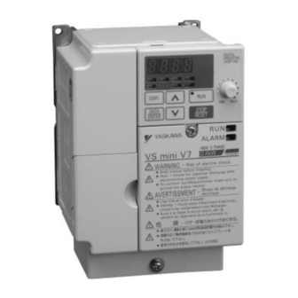
Page 17: Identifying The Parts
2. IDENTIFYING THE PARTS Artisan Technology Group - Quality Instrumentation ... Guaranteed | (888) 88-SOURCE | www.artisantg.com... - Page 18 Main Circuit Terminal Arrangement Terminal arrangement of the main circuit terminal differs depending on the inverter model. The terminal arrangement for200/400V, 3-Phase input series 7.5/10 HP (5.5/7.5Kw) is shown below. Artisan Technology Group - Quality Instrumentation ... Guaranteed | (888) 88-SOURCE | www.artisantg.com...
-
Page 19: Mounting
3. MOUNTING • Choosing a Location to Mount the Inverter Be sure the inverter is protected from the following conditions: • Extreme cold and heat. Use only within the ambient temperature range (for open chassis type): 14 to 122°F (-10 to +50°C). •... -
Page 20: Mounting Dimensions
• Mounting Dimensions To mount the VS 606 V7, dimensions as shown below are required. Max. Applicable Voltage Motor Output Length of A HP (Kw) 200V Single - phase Less than More than 3 - phase 5 HP (3.7 Kw) 1.18in (30mm) 400V 3 - phase... -
Page 21: Mounting/Removing Components
• Mounting/Removing Components Removing and Mounting Digital Operator and Covers NOTE: Mount the inverter after removing the front cover, digital operator and terminal cover. • Removing front cover Use a screwdriver to loosen the screw on the front cover surface to direction 1 to remove it. - Page 22 • Removing digital operator After removing the front cover, lift the upper and lower sides (section A) of the right side of the digital operator to direction 1. • Mounting digital operator Mount the digital operator in the reverse order of the above procedure for removal. •...
-
Page 23: Wiring
4. WIRING • Wiring Instructions (1) Always connect the power input terminals R/L1, S/L2, and T/L3 (R/L1, S/L2 for single-phase) and power supply via a molded-case circuit breaker (MCCB). Never connect them to U/T1, V/T2, W/T3. The single-phase (200V class) inverter can be connected to a 200V 3-phase input. However, when terminal T/L3 is connected to single-phase, never use the terminal for other purposes. -
Page 24: Wire And Terminal Screw Sizes
• Wire and Terminal Screw Sizes 1. Control Circuit Wire Tightening Recommend Applicable size Model Terminal Symbol Screw Torque size Type lb • in (N • m) 4.44 to 5.33 twisted wire 0.5 to 1.25 20 to 16 MA, MB, MC 0.75 Common (0.5 to 0.6) - Page 25 200V Class Single-phase Input Series Wire Tightening Applicable Recommended Torque Model Terminal Symbol Screw size size lb • in Type (N • m) R/L1,S/L2,T/L3,-,+1,+2,B1,B2,U/T1,V/T2,W/T3 7.1 to 8.88 18 to CIMR-V7AAB0P1 M3.5 0.75 to 2 (0.8 to 1.0) R/L1,S/L2,T/L3,-,+1,+2,B1,B2,U/T1,V/T2,W/T3 7.1 to 8.88 18 to CIMR-V7AAB0P2 M3.5...
-
Page 26: Wiring The Main Circuit
• Wiring the Main Circuit L1 L2 L3 [Example of 3-phase 400V class, 0.37 inverters] • Main circuit input power supply Connect the power supply wiring to input terminals L1 (R), N/L2(S) and L3(T) • Braking resistor connection [L1(R), N/L2(S) for single-phase (optional). -
Page 27: Wiring The Control Circuit
• Wiring the Control Circuit Only basic insulation is provided for the control circuit terminals. Additional insulation may be necessary in the end product. • Control Circuit terminals Pass the cable through wiring hole and connect. Be sure to mount all the covers on the original position. -
Page 28: Wiring Inspection
Open the front cover and verify that the strip length is 0.22 in. (5.5mm) • Wiring Inspection After completing wiring, check the following: • Wiring is properly connected. • Wire clippings or screws are not left inside the unit. • Screws are securely tightened. •... -
Page 29: Operating The Inverter
5. OPERATING THE INVERTER Initial setting of control mode selection (n002) is set at V/f control mode. • Test Run The inverter operates by setting the frequency (speed). There are three types of operation modes for the VS-606V7: 1. Run command from the digital operator (local potentiometer/digital setting). 2. - Page 30 Operator 12-LED Status Operation Steps Display Display Indicator LED 1. Turn ON the power supply. 6.00 FREF ALARM 2. Set parameter n004 to 1. PRGM ALARM 3. Set the following parameters. n019 : 15.0 (acceleration time) 15.0 PRGM n020 : 5.0 (deceleration time) ALARM 4.
-
Page 31: Operating The Digital Operator
• Operating the Digital Operator All functions of the VS-606V7 are set by the digital operator. Below are descriptions of the display and keypad sections. Digital Operator JVOP-140 Artisan Technology Group - Quality Instrumentation ... Guaranteed | (888) 88-SOURCE | www.artisantg.com... - Page 32 Description of Status Indicator LED’s There are two LED’s on the middle right section of the face of the VS-606V7. The inverter status is indicated by various combinations of ON, BLINKING and OFF LED’s. RUN indicator and status indicator of the button have the same functions.
-
Page 33: Led Description
• LED Description By pressing on the digital operator, each of the function LED’s can be selected. The following flowchart describes each function LED. If the VS-606V7 loses power while in one of these modes, it will return to this mode once power is restored. - Page 34 Return to Multi-Function monitor • Selecting monitor Press key. When is ON, data can be displayed by selecting monitor No. [Example] Monitoring Output Voltage Reference Artisan Technology Group - Quality Instrumentation ... Guaranteed | (888) 88-SOURCE | www.artisantg.com...
- Page 35 • Monitoring Following items can be monitored by U-parameter parameter Name Description Frequency reference Frequency reference can be monitored. U-01 ¹ (FREF)* (Same as FREF) Output frequency Output frequency can be monitored. U-02 ¹ (FOUT)* (Same as FOUT) Output current Output current can be monitored.
- Page 36 Artisan Technology Group - Quality Instrumentation ... Guaranteed | (888) 88-SOURCE | www.artisantg.com...
- Page 37 Fault history display method When U-09 is selected, a four-digit box is displayed. The three digits from the right show the fault description, and the digit on the left shows the order of fault (from one to four). Number 1 represents the latest fault, and 2, 3, 4, in ascending order of fault occurrence.
-
Page 38: Simple Data Setting
• Simple Data Setting Digital setting (Refer to 5, OPERATING THE INVERTER) and potentiometer setting are both available for simple accel/decel operation of the VS-606V7. Frequency reference by analog voltage is set with initial setting (n004 = 1). For the model with digital operator (with potentiometer) JVOP-140, factory setting is set by frequency setting potentiometer (n004=0). - Page 39 Notes Artisan Technology Group - Quality Instrumentation ... Guaranteed | (888) 88-SOURCE | www.artisantg.com...
-
Page 40: Programming Features
6. PROGRAMMING FEATURES Factory settings of the parameters are shown as in the tables. • Parameter Set-up and Initialization Parameter selection/initialization (n001) The following table describes the data which can be set or read when n001 is set. Unused parameters among n001 to n179 are not displayed. n001 Setting Parameter that can be set Parameter that can be referred... -
Page 41: Using V/F Control Mode
• Using V/f Control Mode Vector control mode is preset at the factory. Control mode selection (n002): 0: V/f control mode (initial setting) 1: Vector control mode Adjusting torque according to application Adjust motor torque by using “V/f pattern” and “full-range automatic torque boost”. •... - Page 42 • Typical setting of V/f pattern Set the V/f pattern according to the application as described below. For 400V class, the voltage values (n012, n015, and n017) should be doubled. When running at a frequency exceeding 50Hz/60Hz, change the maximum output frequency (n011). Note: Be sure to set the maximum output frequency according to the motor char- acteristics...
- Page 43 • Full-range automatic torque boost (when V/f mode is selected. n002=0) Motor torque requirement changes according to load conditions. Full range automatic torque boost adjusts voltage of V/f pattern according to the requirement. The VS-606V7 automatically adjusts the voltage during parameter-speed operation as well as during acceleration.
-
Page 44: Using Vector Control Mode
1: Vector control mode • Precaution for voltage vector control application Since vector control needs motor parameters, the YASKAWA standard motor parameters have been set at the factory prior to shipment. Therefore, when an inverter exclusive-use motor is used or when a motor of any other manufacturer is driven, the required torque characteristics or speed control characteristics may not be maintained because the parameters are not matched. - Page 45 Select slip compensation status during regeneration N113 Setting Slip Compensation during Regeneration Disabled Enabled • Motor parameter calculation The following shows an example of motor parameter calculation: (1) Motor rated slip (n106) × 120 motor rated frequency (Hz) -------------------------------------------------------------------------------------------- - Motor rated speed (r/min) –...
- Page 46 • V/f pattern during vector control Set V/f pattern as follows during vector control. The following examples are for 200V class motors. When using 400V class motors, double voltage settings (n012, n015, n017). When operating with frequency larger than 60Hz/50Hz, change only maximum output frequency (n011).
-
Page 47: Switching Local/Remote Modes
• Switching LOCAL/REMOTE Modes The following functions can be selected by switching the LOCAL or REMOTE mode. To select RUN/STOP commands or frequency reference, change the mode in advance depending on the following applications. • LOCAL mode: Enables the digital operator for RUN/STOP commands and FWD/REV run commands. -
Page 48: Selecting Run/Stop Commands
• Selecting Run/Stop Commands Refer to Switching LOCAL/REMOTE Modes (Page 44) to select either the LOCAL mode or REMOTE mode. Operation method (RUN / STOP commands, FWD / REV run commands) can be selected by the following method. • LOCAL Mode When Lo (local mode) is selected by digital operator ON mode, or when the LOCAL / REMOTE switching function is set and the input terminals are... - Page 49 • Operating (RUN /STOP commands) by communications Setting parameter n003 to 2 in REMOTE mode can give RUN / STOP commands by communication (MEMOBUS communications). For the command by transmission, refer to page 89). • Selecting Frequency Reference Frequency reference can be selected by the following methods. •...
- Page 50 Example of frequency reference by voltage signal Artisan Technology Group - Quality Instrumentation ... Guaranteed | (888) 88-SOURCE | www.artisantg.com...
-
Page 51: Setting Operation Condition
• Setting Operation Conditions Reverse run prohibit (n006) “Reverse run prohibit” setting does not accept a reverse run command from the control circuit terminal or digital operator. This setting is used for applications where a reverse run command can cause problems. Setting Description Reverse run enabled... - Page 52 Additional settings for 16-Step speed operation Set n120 ~ n127 to frequency reference 9-16. A multi-function input must be set to multi-step speed reference 4 (n050 ~ n056 = 9). Operating at low speed By inputting a jog command and then a forward (reverse) run command, operation is enabled at the jog frequency set in n032.
- Page 53 • Adjusting speed setting signal To provide frequency reference by analog input of control circuit terminal FR and FC, the relationship between analog input and frequency reference can be set. FREQUENCY REFERENCE (a) Analog frequency reference gain (n060) The frequency reference provided when analog input is 10V(20mA) can be set in units of 1%.
- Page 54 • To operate the inverter with frequency reference of 50% to 100% at 0 to 10V input Artisan Technology Group - Quality Instrumentation ... Guaranteed | (888) 88-SOURCE | www.artisantg.com...
- Page 55 Adjusting frequency upper and lower limits • Frequency reference upper limit (n033) Sets the upper limit of the frequency reference in units of 1%. (n011: Maximum output frequency = 100%) Factory setting: 100% • Frequency reference lower limit (n034) Sets the lower limit of the frequency reference in units of 1%.
- Page 56 Name Unit Setting Range Initial setting n019 Accel time 1 10.0s Refer to n020 Decel time 1 10.0s Refer to n018 n018 n021 Accel time 2 setting 10.0s setting n022 Decel time 2 10.0s n018 setting Unit Setting Range 0.1s 0.0 - 999.9s (999.9s or less) 1000 - 6000s (1000s or more) n018...
- Page 57 Soft-start characteristics (n023) To prevent shock at machine start/stop, accel/decel can be performed in S-curve pattern. Setting S-curve characteristic time S-curve characteristic not provided 0.2 second 0.5 second 1.0 second Note: The S-curve characteristics time is the time from accel/decel rate 0 to a reg- ular accel/decel rate determined by the set accel/decel time.
- Page 58 Torque detection If an excessive load is applied to the machine, the resultant output current increase can be compared to the threshold setting of parameter n098, then output alarm signals to multi-function output terminals MA, MB, P1 and P2. To output an overtorque detection signal, set output terminal function selection n057 to n059 to “overtorque detection”...
- Page 59 • Overtorque detection function selection 1 (n096) Setting Description Overtorque detection not provided Detected during parameter-speed running, and operation continues after detection. Detected during parameter-speed running, and operation stops during detection. Detected during running, and operation continues after detection. Detected during running, and operation stops during detection.
- Page 60 Frequency detection (n095) Effective when either of output terminal function selections n057, n058 or n059 are set to “frequency detection” (setting: 4 or 5). “Frequency detection” turns ON when output frequency is higher or lower than the frequency detection level (n095). •...
- Page 61 Jump frequencies (n083 to n086) This function allows the prohibition or “jumping” of critical frequencies so that the motor can operate without resonance caused by machine systems. This function is also used for dead band control. Setting the value to 0.00Hz disables this function. Set prohibited frequency 1, 2 or 3 as follows: n083 >...
- Page 62 • Cumulative Operation Time Selection (n087) Setting Description Inverter power-on time (Counts the elapsed time that there is an inverter output) Inverter running time (Counts the elapsed time that there is an inverter output.) Cumulative operation time setting. Inverter operating time set with parameter n087 is accumulated by the unit of 10H. Accumulation starts from the time set with parameter n088.
- Page 63 • Input / Output Open Phase Protection Parameters Setting Initial Name Unit Range Setting 0 to 100% *1 400.0V/100% Input open-phase n166 (for 200V class) detection level 800.0V/100% (for 400V class) Input open-phase n167 1 sec. 0 to 255 sec. *2 0 sec.
- Page 64 • Speed search command Restarts a coasting motor without stopping it. This function enables smooth switching between motor commercial power supply operation and inverter operation. Set input terminal function selection (n050 to n056) to “14” (search command from maximum output frequency) or “15” (search command from set frequency). Build a sequence so that FWD (REV) run command is input at the same time as the search command or after the search command.
- Page 65 Holding accel/decel temporarily To hold acceleration or deceleration, input accel/decel hold command. The output frequency is maintained when the accel/decel hold command is input during acceleration or deceleration. When the stop command is input during accel/decel prohibition command input, accel/ decel hold is released and operation ramps to stop.
- Page 66 Using frequency meter or ammeter (n066) Selects the function to be monitored at analog output terminals AM-AC. Setting Description Output frequency Output current Main circuit DC voltage Torque monitor Output power Output voltage reference In initial setting, analog voltage of approx. 10V is output when output frequency (output current) is 100%.
- Page 67 Using analog output (AM-AC) as a pulse train signal output (n065) Analog output AM-AC can be used as a pulse train output (output frequency monitor). Set n065 to 1 when using pulse train output. Parameters No. Name Unit Setting range Initial Setting n065 Monitor output type selection...
- Page 68 Peripheral devices must be connected according to the following load conditions NOTE when using pulse monitor output. The machine might be damaged when the con- ditions are not satisfied. Used as a sourcing output Output voltage Load impendance VRL (V) (kΩ) 1.5 kΩ...
- Page 69 Reducing motor noise leakage current (n080) Set inverter output transistor switching frequency (carrier frequency). Metallic Noise Noise and Current Setting Carrier Frequency (kHz) from Motor Leakage 12 fout (Hz) Higher Smaller 24 fout (Hz) 36 fout (Hz) (kHz) (kHz) Larger (kHz) audible 10.0...
- Page 70 Reducing Motor Noise or Leakage Current (n080) Frequency setting varies according to inverter capacity (kVA). Initial Setting Maximum Capacity Continuous Reduced Voltage Class (V) Carrier (kW) Output Current Current (A) Setting Frequency 10kHz 10kHz – 10kHz 10kHz Single-phase 3- 7.5kHz phase 7.5kHz 11.0...
- Page 71 (3) Set carrier frequency (n080) to either 1, 2, 3, 4 when using vector con- trol mode. Do not set to 7, 8, or 9. (4) Carrier frequency is automatically reduced to 2.5kHz when reducing carrier frequency selection at low speed (n175) is set to 1 and the fol- lowing conditions are satisfied: Output frequency <...
-
Page 72: Selecting Stopping Method
Selecting stopping method (n005) Selects the stopping method suitable for application. Setting Description Deceleration to stop Coast to stop • Deceleration to stop Example: when accel/decel time 1 is selected * When frequency reference is changed during running. Upon termination of the FWD (REV) run command, the motor decelerates at the decel rate determined by the time set to decel time 1 (n020) and DC injection braking is applied immediately before stop. - Page 73 • Coast to stop Example: when accel/decel time 1 is selected * When frequency reference is changed during running. Upon removal of the FWD (REV) run command, the motor starts coasting. Applying DC injection braking • DC injection braking current (n089) Sets DC injection braking current in units of 1%.
-
Page 74: Building Interface Circuits With External Devices
• Building Interface Circuits with External Devices Using input signals Multi-function input terminal S1 to S7 functions can be changed when necessary by setting parameters n051 or n052 respectively. The same value cannot be set to different parameter settings. Setting Name Description Ref. - Page 75 Initial setting Terminal Initial Setting Function n050 Forward run command (2-wire sequence) n051 Reverse run command (3-wire sequence) n052 External fault n053 Fault reset n054 Multi-step speed reference 1 n055 Multi-step speed reference 2 n056 JOG command Terminal function at 3-wire sequence selection When 0 is set at the terminal S3 (n052), terminal S1 becomes run command, terminal S2 becomes stop command, and terminal S3 becomes FWD/REV run command.
- Page 76 (Example:)Set n003 = 1, n004 = 2, n008 = 0. Open: Run by frequency reference from multi-function input terminal FR and run command from multi-function input terminals S1 to S7. Closed: Run by potentiometer frequency reference and run command from the digital operator.
- Page 77 Time Chart at UP/DOWN Command Input Artisan Technology Group - Quality Instrumentation ... Guaranteed | (888) 88-SOURCE | www.artisantg.com...
- Page 78 Notes: (1) When UP/DOWN command is selected, the upper limit speed is set regardless of frequency reference. Upper limit speed = Maximum output frequency (n011) x Frequency reference upper limit (n033)/100 (2) Lower limit value is either minimum output frequency (n016) or frequency reference lower limit (n034) (whichever is greater).
- Page 79 • Communication/multi-function input terminal selection input (setting: 18) Operation can be changed from communication command, or from multi-function input terminal or digital operator command. Run command from communication and frequency reference are effective when multi-function input terminal for this setting is “closed (register No. 0001H, 0002H).”...
- Page 80 n077 setting Setting Name Description Disabled The multi-function input is disabled Auxiliary frequency When frequency reference 2 is selected in multi-step reference (FREF2) speed reference, the input analog signal for the CN2 terminal becomes the frequency reference. The n025 setting becomes invalid. Note: Set frequency reference gain to n068 or n071, and frequency reference bias to n069 or no72.
- Page 81 Analog input level Frequency reference gain (n077=2) Auxiliary frequency reference (n077=1) FREF2 FGAIN Frequence reference bias (n077=3) Output voltage bias (n077=4) The VBIAS value to be added is doubled for 400V class inverters. Artisan Technology Group - Quality Instrumentation ... Guaranteed | (888) 88-SOURCE | www.artisantg.com...
- Page 82 Multi-function analog input signal selection (n078) Setting Initial Parameter No. Name Unit Range Setting 0 = Digital operator terminal Multi-function analog (voltage: 0 to 10V) n078 input signal selection 1 = Digital operator terminal (current: 4 to 20mA) Frequency reference bias setting (n079) Setting Initial Parameter No.
- Page 83 Using output signals (n057, n058, n059) Multi-function output terminal MA, MB, P1 and P2 functions can be changed when necessary by setting parameters n057, n058, and n059. • Terminal MA and MB functions: Set to n057 • Terminal P1 function: Set to n058 •...
-
Page 84: Setting Frequency By Current Reference Input
• Setting Frequency by Current Reference Input When setting frequency by inputting current reference (4-20mA or 0-20mA) from the control circuit terminal FR, switch the DIP switch SW1 on the control circuit board to “I” side. SW1 is accessed by removing the digital operator. - Page 85 Current reference selection After changing DIP switch (V/I switch of SW2) to the “I” side, PRESS on the PRGM digital operator, then set the following parameters. Current reference (4-20mA) parameter n004=3 Current reference (0-20mA) parameter n004=4 Press the digital operator keys to run or stop the inverter.
-
Page 86: Frequency Reference By Pulse Train Input
• Frequency Reference by Pulse Train Input Frequency reference can be set by pulse train input from the multi-function input terminal. • Input pulse specifications • Low-level voltage: 0.8V or less • High-level voltage: 3.5 to 32V • Duty Cycle: 30 to 70% •... - Page 87 Preventing Motor from Stalling (Current Limit) Automatically adjusts the output frequency and output current according to the load to continue operation without stalling the motor. • Stall prevention (current limit) level during acceleration (n093) Sets the stall prevention (current limit) level during acceleration in units of 1% (Inverter rated current = 100%).
- Page 88 • Stall prevention (current limit) level during running (n094) Sets the stall prevention (current limit) level during running in units of 1% (Inverter current = 100%). • Factory setting: 160% A setting of 200% disables the stall prevention (current limit) during running. If the inverter is at speed agree and output current exceeds the value set for n094 for longer than 100msec, deceleration starts.
- Page 89 n115 setting Setting Function The stall prevention level becomes the level set for the parameter n094 in all frequency areas The following shows that the stall prevention level is automatically decreased in the parameter output range (Max. frequency>Max. voltage output frequency). The lower limit is 40% of the set value of n094.
-
Page 90: Decreasing Motor Speed Fluctuation
• Decreasing Motor Speed Fluctuation Slip compensation (When V/f control mode n002=0) As the load becomes larger, motor speed is reduced and motor slip value is increased. The slip compensating function controls the motor speed at a parameter value even if the load varies. -
Page 91: Motor Protection
• Motor Protection Motor overload detection The VS-606V7 protects against motor overload with a built-in electronic thermal overload relay. • Motor rated current (electronic thermal reference current, n036) Set to the rated current value shown on the motor nameplate. Note: Setting to 0.0A disables the motor overload protective function. - Page 92 • General-purpose motor and inverter duty motor Induction motors are classified as general-purpose motors or inverter motors, based on their cooling capabilities. Therefore, the motor overload function operates differently between these two motor types. Example of 200V class motor Electronic Thermal Cooling Effect Torque Characteristics overload...
-
Page 93: Selecting Cooling Fan Operation
• Selecting Cooling Fan Operation In order to increase lifetime, the cooling fan can be set to operate only when inverter is running. n039 = 0 (factory setting) : Operates only when inverter is running. (Continuous operation for 1 minute after inverter is stopped.) : Operates with power ON. - Page 94 • Communications connection terminal Use the following S+, S-, R+ and R- terminals for MEMOBUS communications. Change the termination resistor as shown below. At RS-422, RS-485 communications: Turn ON SW2 ON/OFF switch of only the inverter at the termination viewed from the PLC. Notes: 1.
- Page 95 • Setting necessary parameters for communication Communication related parameters must be set for PLC communication. parameters n151 to n157 cannot be set during communication. Always set them prior to performing communication. Initial Parameter Name Description Setting 0 : operator 1 : control circuit terminals n003 Run command selection 2 : communication...
- Page 96 • Message format For communications, the master (PLC) sends a command Slave address to the slave (VS-606V7) and the slave responds to it. The Function code configuration for sending and receiving is as shown to the right. The length of the data varies according to the Data contents of commands (functions).
- Page 97 • Read out holding register contents [03H] Reads out the contents of the holding registers with the continuous numbers for the specified quantity. The contents of holding register is divided into the upper 8 bits and the lower 8 bits. They become the data items in response message in the order of numbers.
- Page 98 • Writing to several holding registers [10H] Specified data are written into the several specified holding registers from the specified number, respectively. Written data must be arranged in a command message in the order of the holding register numbers: from upper eight bits to lower eight bits. Example: Set forward run at frequency reference 60.0 Hz to slave 1 VS-606V7 from the PLC.
- Page 99 • Data • Reference Data (available to read out/write in) Register No. Description 0000H Reserved Run command 1 : Run 0 : Stop Reverse run 1 : Reverse run 0 : Forward run External fault 1 : Fault (EFO) Fault reset 1 : Reset command Multi-function input reference 1 (Function selected by n050)
- Page 100 • Monitor Data (available only for read out) Register No. Description Run command 1 : Run 0 : Stop Reverse run 1 : Reverse run 0 : Forward run Inverter operation ready 1 : Ready 0 : Not ready Fault 1 : Fault 0020H Data setting error...
- Page 101 Register No. Description Operator stop (STP) Sequence error (SER) FWD - REV command simulation input (EF) External baseblock (BB) Overtorque detection (OL3) Cooling fin overheat (OH) Main circuit overvoltage (OV) Main circuit undervoltage 002AH Cooling fan fault (FAN) Communication error Option card communication error (BUS) Not used Inverter overheat prediction (OH3)
- Page 102 Register No. Description Frequency ref. loss Not used Not used Not used 02EH Not used Not used Not used Not used 8 - F Not used 002FH-0030H Reserved 0031H Main circuit DC voltage (1/1V) 0032H Torque monitor 0033H-0034H Not used 0035H Cumulative operation time (I/IH) 0036H...
- Page 103 • Storing parameters [Enter command] (can be written only.) Register Name Contents Setting Range Default Number ENTER Write-in parameter data to non- 0900H 0000H to FFFFH command volatile memory (EEPROM). When a parameter is written from the PLC by communications, the parameter is written to the parameter data area on the RAM in the VS-606V7.
-
Page 104: Error Codes
Error Codes Error Code Contents Function code error • Function code from PLC is other than 03H, 08H or 10H. Improper register number • No register numbers to be accessed have been registered. • ENTER command “0900H” that is an exclusive-use register for write-in was read out. Improper quantity •... - Page 105 • Performing self-test VS-606V7 is provided with a function to perform self-diagnosis for operation check of the serial communication I/F circuit. This function is called self-test. In the self-test, connect the sending terminal with the receiving terminal in the communication section. It assures if the data received by VS-606V7 is not being changed.
- Page 106 Calculates the voltage for the best motor efficiency when operating in energy- saving control mode. The calculated voltage becomes the output voltage reference. The factory setting is set to the max. applicable motor capacity of a Yaskawa standard motor. The greater the energy-saving coefficient is, the greater the output voltage becomes.
- Page 107 • Energy-saving voltage lower/upper limit (n141, n142, n159, n160) Sets the upper and lower limits of the output voltage. When the value calculated in the energy-saving control mode is larger than the upper limit (or smaller than the lower limit), the value is output as a voltage reference value. The upper limit is set to prevent over-excitation, and the lower limit is set to prevent stalls when the load is light.
- Page 108 Energy-saving search operation In the energy control mode, the max. applicable voltage is calculated using the output power. However, a temperature change or the use of another manufacturer’s motor will change the fixed parameters, and the max. applicable voltage may not be emitted. In the search operation, change the voltage slightly so that the max.
- Page 109 • Search Operation Power Detection Hold Width (n161) When the power fluctuation is less than this value, the output voltage is held for 3 seconds. Then the search operation mode is activated. Set the hold width in % of the power which is currently held.
- Page 110 356.9 0.4 kW 288.2 0.75 kW 223.7 200V 1.5 kW 169.4 2.2 kW 156.8 3.7 kW 122.9 5.5 kW 94.8 YASKAWA 7.5 kW 72.7 General- purpose 0.2 kW 713.8 Motor 0.4 kW 576.4 0.75 kW 447.4 1.5 kW 338.8 400V 2.2 kW...
-
Page 111: Using Pid Control Mode
• Using PID Control Mode For details of the PID control setting, refer to the block diagram of the Inverter’s internal PID control or the block diagram of the operator analog speed reference. PID Control Selection: n128 Parameter Setting Initial Name Unit Range... - Page 112 Notes: 1. When selecting frequency reference from the control circuit terminal FR as the target or feedback value, the V-I switch of SW2 on the control circuit board must be selected depending on the input method (current or voltage input). 2.
- Page 113 • Intregal (I) Limit (n134) Parameter Setting Initial Name Unit Range Setting n134 Intregal (I) limit 0 to 100 This parameter prevents the calculated value of the integral control from exceeding the fixed amount. There is normally no need to change the setting. Reduce the setting if there is a risk of load damage, or of the motor going out of step by the inverter’s response when the load suddenly changes.
- Page 114 • PID Output Gain (n163) Parameter Setting Initial Name Unit Range Setting n163 PID Output gain Multiples 0.0 to 25.0 This parameter adjusts the output gain. • PID Feedback Value Adjusting Gain (n129) Parameter Setting Initial Name Unit Range Setting PID feedback value n129 Multiples...
- Page 115 Artisan Technology Group - Quality Instrumentation ... Guaranteed | (888) 88-SOURCE | www.artisantg.com...
- Page 116 Artisan Technology Group - Quality Instrumentation ... Guaranteed | (888) 88-SOURCE | www.artisantg.com...
-
Page 117: Using Parameter Copy Function
• Using Parameter Copy Function Parameter copy function The VS-606V7 standard digital operator JVOP-140 can store parameters for one inverter. A backup power supply is not necessary since EEPROM is used. Parameter copy function is possible only for the inverters with the same product series, power supply specifications and control mode (V/f control or vector control). - Page 118 Parameter Setting Initial Name Unit Range Setting rdy: READY rEd: READ CPy: COPY vFy: Verify n176 Parameter copy function selection vA: Inverter capacity display Sno: Software number display • Prohibiting Parameter Read Selection (n177) Select this function to prevent accidentally overwriting the parameters stored in EEPROM or in the digital operator.
- Page 119 [Example] Store the parameters read out from the inverter, in the EEPROM inside the digital operator Explanation Operator display • Enable the setting of the • Press DSPL to light [PRGM]. parameters n001 to n179. • Press ENTER to display the set (Can be a different parameter No.) value.
- Page 120 Copy Function Writes the parameters stored inside the digital operator in batch to the inverter. Write-in is possible only for the inverters with the same product series, power supply specifications and control mode (V/f control or vector control). Therefore, writing from 200 V class to 400 V class (or visa versa), from VS-606V7 to VSmini J7 are not possible.
- Page 121 A setting range check and matching check for the written-in parameters are executed after the parameters are written from the digital operator to the inverter. If any parameter error is found, the written parameters are discarded and the parameters stored before writing are restored. When a setting range error is found, the parameter No.
- Page 122 VERIFY function Collates the parameters stored in the digital operator with the parameters in the inverter. As well as write-in, VERIFY is possible only for the inverters with same product series, power supply specifications and control mode (V/f control or vector control).
- Page 123 Inverter Capacity Display The voltage class and maximum applicable motor capacity (whose parameters stored in the digital operator are read out) is displayed. [Example] Display the voltage class and maximum applicable motor capacity for the inverter whose parameters stored in EEPROM inside the digital operator.
- Page 124 Software No. Display The software No. (of the inverter whose parameters stored in the digital operator are read out) is displayed. [Example] Display the software No. of the inverter whose parameters stored in EEPROM inside the digital operator. Explanation Operator display •...
- Page 125 Display List Operator Description Corrective action display Lit: Setting for parameter copy function selection enabled Lit: READ selected Flashed: READ under execution Lit: Writing (COPY) selected Blinks: Writing (COPY) under execution Lit: VERIFY selected Flashed: VERIFY under execution Lit: Inverter capacity display selected Lit: Software No.
-
Page 126: Unit Selection For Frequency Reference Setting Display
• Unit selection for Frequency Reference Setting/ Display Parameter and monitor display for which selection of unit function is valid Item Contents Frequency reference 1 to 8 (Parameters n024 to n031) Frequency reference Jog frequency reference (Parameters n032) parameters Frequency reference 9 to 16 (parameters n120 to n127) Frequency reference display (FREF) Output frequency display (FOUT) Monitor display... - Page 127 Parameter n035 Description Setting • Set the display value at 100% of frequency reference (set value of Fmax(n011)) at 1st to 4th digit of n035. By a number of 4th digit of n035, set the position of decimal point. By 1st to 4th digit of n035, set a 3-digit figure excluding decimal point. Number of 4th digit.
-
Page 128: Maintenance And Inspection
7. Maintenance and Inspection • Periodical Inspection Periodically inspect the inverter as described in the following table to prevent accidents and to ensure high performance with high-reliability. Location to Check Check For Solution Terminal, unit mounting Connection hardware is properly Properly seat and tighten hardware. - Page 129 Replacement of cooling fan • Inverter of W-dimension (width) 2.68 inches (68mm), 5.51 inches (140mm), 6.69 inches (170mm), and 7.09 inches (180mm). 1. Removal (1) Press the right and left clicks of the fan cover to direction 1, and then pull them to direction 2 to remove the fan cover from the inverter unit.
-
Page 130: Fault Diagnosis And Corrective Actions
8. Fault Diagnosis and Corrective Actions This section describes the alarm and fault displays, explanations for fault conditions and corrective actions to be taken if the VS-606V7 malfunctions. < Corrective Actions for models with blank cover > 1. Input fault reset or cycle the power supply OFF and ON. 2. - Page 131 < Corrective Actions of models with digital operator > : ON : Blinking : OFF Alarm Display and Contents Alarm Display Inverter Causes and Explanation Digital RUN (Green) Status Corrective Actions Operator ALARM (Red) UV (Main circuit low voltage) Check the following: Main circuit DC voltage drops •...
- Page 132 Alarm Display Inverter Causes and Explanation Digital RUN (Green) Status Corrective Actions Operator ALARM (Red) OP…(parameter setting error Check the setting when the parameter setting is values. performed through the MEMOBUS communications) OP1: Two or more values are set for multi-function input selection.
- Page 133 Alarm Display Inverter Causes and Explanation Digital RUN (Green) Status Corrective Actions Operator ALARM (Red) BB (External baseblock) Check the external Baseblock command at multi- circuit (sequence). function terminal is active. The inverter output is shut OFF (motor coasting). Blinking Temporary condition is cleared when input command is removed.
- Page 134 Alarm Display Inverter Causes and Explanation Digital RUN (Green) Status Corrective Actions Operator ALARM (Red) OC (Over current) • Short circuit or Inverter output current grounding at inverter momentarily exceeds approx. output side. 250% of rated current. • Excessive load WK •...
- Page 135 Alarm Display Inverter Causes and Explanation Digital RUN (Green) Status Corrective Actions Operator ALARM (Red) UV2 (Control power supply Cycle power. fault) If the fault remains, Voltage fault of control power replace the inverter. supply is detected. (Main Circuit Voltage Fault)* •...
- Page 136 Alarm Display Inverter Causes and Explanation Digital RUN (Green) Status Corrective Actions Operator ALARM (Red) RH (Installed type braking • The declaration time resistor overheating) is too short. • The regenerative The protection function has energy from the operated. motor is too large. ⇓...
- Page 137 Alarm Display Inverter Causes and Explanation Digital RUN (Green) Status Corrective Actions Operator ALARM (Red) EF‰ Check the external (External fault) circuit (sequence). Inverter receives an external fault input from control circuit terminal. EF0: External fault reference through MEMOBUS communications EF1: External fault input command from control circuit terminal S1...
- Page 138 Alarm Display Inverter Causes and Explanation Digital RUN (Green) Status Corrective Actions Operator ALARM (Red) CPF-05 Cycle power. AD converter fault is detected If the fault remains replace the inverter. CPF-06 Remove power to the • Option card connecting inverter. fault Check the connection •...
- Page 139 Alarm Display Inverter Causes and Explanation Digital RUN(Green) Status Corrective Actions Operator ALARM(RED) STP (Emergency stop) Check the external The inverter stops according circuit (sequence). to parameter n005 after receiving the emergency stop fault signal. FBL (PID feedback loss Stops detection) according to PID feedback value drops...
-
Page 140: Specifications
9. Specifications • Standard Specifications (200V Class) Voltage Class 200V single- / 3-phase 3-phase 20P1 20P2 20P4 20P7 21P5 22P2 23P7 25P5 27P5 Model CIMR-V7*C‰‰‰‰ Single-phase B0P1 B0P2 B0P4 B0P7 B1P5 B2P2 B3P7 Max. Applicable Motor Output kW* 0.25 0.55 Inverter Capacity (kVA) Rated Output Current (A) 17.5... - Page 141 Voltage Class 200V single- / 3-phase 3-phase 20P1 20P2 20P4 20P7 21P5 22P2 23P7 25P5 27P5 Model CIMR-V7*C‰‰‰‰ Single-phase B0P1 B0P2 B0P4 B0P7 B1P5 B2P2 B3P7 Motor Overload Protection Electronic thermal overload relay Motor coasts to a stop at approx. 250% of inverter rated Instantaneous Overcurrent current Motor coasts to a stop after 1 minute at 150% of inverter...
- Page 142 Voltage Class 200V single- / 3-phase 3-phase 20P1 20P2 20P4 20P7 21P5 22P2 23P7 25P5 27P5 Model CIMR-V7*C‰‰‰‰ Single-phase B0P1 B0P2 B0P4 B0P7 B1P5 B2P2 B3P7 Status Indicator LED RUN and ALARM provided as standard LEDs Digital Operator Available to monitor frequency reference, output (JVOP-140) frequency, output current Main circuit: screw terminals...
-
Page 143: Standard Specifications (400V Class)
• Standard Specifications (400V Class) Voltage Class 400V 3-phase 3-phase 40P2 40P4 40P7 41P5 42P2 43P0 43P7 45P5 47P5 Model CIMR-V7*C‰‰‰‰ Single-phase – – – – – – – – – Max. Applicable Motor Output HP 0.75 (kW)* (0.2) (0.4) (0.75) (1.5) (2.2) - Page 144 Voltage Class 400V 3-phase 3-phase 40P2 40P4 40P7 41P5 42P2 43P0 43P7 45P5 47P5 Model CIMR-V7*C‰‰‰‰ Single-phase – – – – – – – – – Motor Overload Protection Electronic thermal overload relay Motor coasts to a stop at approx. 250% of inverter rated Instantaneous Over Current current Motor coasts to a stop after 1 minute at 150% of inverter...
- Page 145 Voltage Class 400V 3-phase 3-phase 40P2 40P4 40P7 41P5 42P2 43P0 43P7 45P5 47P5 Model CIMR-V7*C‰‰‰‰ Single-phase – – – – – – – – – Status Indicator LED RUN and ALARM provided as standard LEDs Digital Operator Available to monitor frequency reference, output (JVOP-140) frequency, output current Main circuit: screw terminals...
-
Page 146: Standard Wiring
• Standard Wiring FOR SINGLE-PHASE USE R\LI AND S\L2 (MAX. 33kHz) Artisan Technology Group - Quality Instrumentation ... Guaranteed | (888) 88-SOURCE | www.artisantg.com... - Page 147 Connection Example of Braking Resistor Artisan Technology Group - Quality Instrumentation ... Guaranteed | (888) 88-SOURCE | www.artisantg.com...
-
Page 148: Terminal Description
Terminal Description Type Terminal Name Function (Signal Level) R/L1, Always use terminal R/L1, S/L2 for single-phase S/L2, AC power supply input inverters. T/L3 Never connect to terminal T/L3. U/T1, V/T2, Inverter output Inverter output W/T3 B1, B2 Braking resistor connection Braking resistor connection When connecting optional DC reactor, remove the main +2, +1 DC reactor connection... -
Page 149: Sequence Input Connection With Npn/Pnp Transistor
• Sequence input connection with NPN/PNP transistor When connecting sequence inputs (S1 to S7) with transistor, turn the rotary switch SW1 depending on the polarity (0V common: NPN side, +24V common: PNP side). Factory setting: NPN side Sequence connection with NPN transistor (0V common) Artisan Technology Group - Quality Instrumentation ... - Page 150 Sequence connection with PNP transistor (+24V common) Artisan Technology Group - Quality Instrumentation ... Guaranteed | (888) 88-SOURCE | www.artisantg.com...
-
Page 151: Dimensions
• Dimensions Fig. 2 Artisan Technology Group - Quality Instrumentation ... Guaranteed | (888) 88-SOURCE | www.artisantg.com... - Page 152 Dimensions in inches (mm)/mass in lb (kg) /Heat Loss (W) Heat Loss (W) Voltage Capacity d Mass Fig. Heat- class HP(kW) Unit Total sink 0.13 2.68 5.83 2.99 2.20 4.65 0.20 5.04 0.79 1.55 13.0 (0.1) (68) (148) (76) (56) (118) (128) (20)
- Page 153 Heat Loss (W) Voltage Capacity d Mass Fig. Heat- class HP(kW) Unit Total sink 4.25 5.83 3.62 3.78 4.65 0.20 5.04 0.79 2.65 13.7 23.1 (0.2) (108) (148) (92) (96) (118) (128) (20) (1.2) 0.75 4.25 5.83 4.43 3.78 4.65 0.20 5.04 0.79...
-
Page 154: Recommended Peripheral Devices
MCCB type NF30 (MITSUBISHI) Magnetic contactor type HI HI-7E HI-7E HI-7E HI-7E HI-10-2E HI-10-2E HI-20E HI-30E HI-50E (YASKAWA CONTROL) Fuse (UL Class RK5) • 200V single-phase V7 ∗ ∗ V7 ∗ ∗ V7 ∗ ∗ V7 ∗ ∗ V7 ∗ ∗... -
Page 155: Parameter List
Surge suppressors Model Surge Suppressors Specifications Code No. Coils and relays DCR2- 250VAC Large size magnetic contactors 50A22E C002417 0.5µF 200Ω 200V Control relays MY-2, -3 (OMRON) 250VAC 230V 10A25C C002482 HH-22, -23 (FUJI) 0.1µF 100Ω MM-2, -4 (OMRON) • Ground fault interrupter: Select a ground fault interrupter not affected by high frequencies. - Page 156 First Functions (Parameters n001 to n049) Register No. for Setting Initial User Ref. Name Setting Range Trans- Unit Setting Setting Page mission Parameter write-in 0 to 4, 6, 8, 9, 0101H prohibit / initialize 12, 13 0 (Note 1) Control mode selection (Note 0102 (Note 6) Operation reference...
- Page 157 Register No. for Setting Initial User Ref. Name Setting Range Trans- Unit Setting Setting Page mission 0.01Hz (less Frequency reference 1 0.00 to than 100Hz) / 0118 (Master speed frequency 6.00Hz 400.0Hz 0.1Hz (100Hz reference) or more) 0.01Hz (less 0.00 to than 100Hz) / 0119 Frequency reference 2...
- Page 158 Second Functions (Parameters n050 to n079) Register No. for Setting Initial User Ref. Name Setting Range Trans- Unit Setting Setting Page mission Multi-function input 1 to 25,26 0132 selection 1 (Note 8) Multi-function input 1 to 25,26 0133 selection 2 (Note 8) Multi-function input 0 to 25,26...
- Page 159 Register No. for Setting Initial User Ref. Name Setting Range Trans- Unit Setting Setting Page mission Analog frequency reference filter time 0146 0.00 to 2.00s 0.01s 0.10s parameter (CN2 V Analog frequency 0147 reference gain -255 to 255% 100% (CN2 I Analog frequency reference bias 0148...
- Page 160 Third Functions (Parameters n080 to n119) Register No. for Setting Initial User Ref. Name Setting Range Trans- Unit Setting Setting Page mission 0150 Carrier frequency 1 to 4, 7 to 9 4 (Note 4) Operation selection after 0151 0, 1, 2 momentary power loss 0152 Fault restart...
- Page 161 Register No. for Setting Initial User Ref. Name Setting Range Trans- Unit Setting Setting Page mission 0.01Hz (less 0.00 to than 100Hz) / 0154 Jump frequency 2 0.00Hz 400.0Hz 0.1Hz (100Hz or more) 0.01Hz (less 0.00 to than 100Hz) / 0155 Jump frequency 3 0.00Hz...
- Page 162 Register No. for Setting Initial User Ref. Name Setting Range Trans- Unit Setting Setting Page mission 0.001Ω (less Motor resistance for one- 0.000 to than 10Ω) / 016B (Note 3) phase 65.50Ω 0.01Ω (10Ω or more) 0.01mH (less 0.00 to than 100mH) / 016C Motor leak inductance...
- Page 163 Register No. for Setting Initial User Ref. Name Setting Range Trans- Unit Setting Setting Page mission Torque compensation 016D 0 to 250% 150% – voltage limiter 016E Motor no-load current 0 to 99% (Note 3) 016F Slip compensation gain 0.0 to 2.5 Slip compensation 0170 0.0 to 25.5s...
- Page 164 Register No. for Setting Initial User Ref. Name Setting Range Trans- Unit Setting Setting Page mission 0.01Hz (less 0.00 to than 100Hz) / 017F Frequency reference 16 0.00Hz 400.0Hz 0.1Hz (100Hz or more) 0180 PID control selection 0 to 8 0181 PID feedback gain 0.00 to 10.00...
- Page 165 Register No. for Setting Initial User Ref. Name Setting Range Trans- Unit Setting Setting Page mission Timeover detection 0197 0 to 4 selection Setting unit selection of communications 0198 0, 1, 2, 3 frequency reference/ frequency monitor 0199 Slave address 0 to 32 019A Baud rate selection...
- Page 166 Notes: 1. Not initialized by parameter initalization. 2. Upper limit and initial setting of setting range are doubled at 400 class. 3. Changes depending on inverter capacity. Refer to the next page. 4. Changes depending on inverter capacity. Refer to page 64. 5.
- Page 167 • 200V class single-phase Name Unit Factory setting – Inverter capacity kW 0.1kW 0.25kW 0.55kW 1.1kW 1.5kW 2.2kW – 3.7kW 5.5kW 7.5kW n036 Motor rated current – 14.1 13.3 Torque n105 compensation iron 11.1 11.8 – 28.8 43.9 loss n106 Motor rated slip –...
-
Page 168: Appendix
Appendix - CE Conformance CE Conformance - Low Voltage Directive (LVD) Compliance These circuits are hazardous and are separated from accessibility by protective separation. These circuits are not separated from hazardous circuits by protective separation, but only with basic insulation. These circuits cannot be accessed and must not be interconnected with any circuits which are accessible, unless they are isolated from accessible circuits by supplemental insulation. - Page 169 (max. 20m) must be used and the screen of the motor cable is connected to ground at both ends by a short connection, using as large an area as practical. For a more detailed explanation, please refer to Making YASKAWA Inverter Products Confirm with EMC Directive (G-TI#99012-V7).
- Page 170 Recommended Line Filters for VS-606V7 made by Rasmi Electronic Ltd ( 200 V three phase) Current Weight Dimension VS-606V7 Model (kg) W×D×H CIMR-V7AU20P1 CIMR-V7AU20P2 RS 2010-V7 82 x 50 x 194 CIMR-V7AU20P4 CIMR-V7AU20P7 CIMR-V7AU21P5 RS 2020-V7 111 x 50 x 169 CIMR-V7AU22P2 CIMR-V7AU23P7 RS 2030-V7...
- Page 171 Appendix 1.2 Installation of Line Filter and VS-606V7 ( single phase ) Mains L2/N Woven Screend L2/N Footprint Screened input cable Filter input cable VS-606V7 U V W PE L1 L2/N Woven Motor Cable Load Screened screened Motor cable Artisan Technology Group - Quality Instrumentation ... Guaranteed | (888) 88-SOURCE | www.artisantg.com...
- Page 172 Appendix 1.3 Installation of Line Filter and VS-606V7 ( 3 phase ) Mains L 1 L 2 Woven Screend L 2 L 3 Footprint Screened input cable Filter input cable VS-606V7 U V W P E L1 L2 L3 Woven Motor Cable Load Screened...
- Page 173 This also applies for equipment with CE approvals. Compliance with the EMC legislation limits is the responsibility of the machine or system manufacturer. RCCBs For information on the use of RCCBs with inverters please contact your supplier or Yaskawa representative. Operation In some systems it may be necessary to install additional monitoring and protective facilities to comply with the applicable safety and accident prevention regulations.
- Page 174 Responsibility As a component manufacturer we are responsible for the provision of installation instructions. These can be found in the installation guidelines publication G-TI#99012-V7 (a Yaskawa publication free upon request). Our products have been tested by authorized bodies pursuant to the requirements of the standard listed below.
- Page 175 YASKAWA ELECTRIC AMERICA, INC. Chicago-Corporate Headquarters 2121 Norman Drive South, Waukegan, IL 60085, U.S.A. Phone: (847) 887-7000 Fax: (847) 887-7310 Internet: http://www.yaskawa.com MOTOMAN INC. 805 Liberty Lane, West Carrollton, OH 45449, U.S.A. Phone: (937) 847-6200 Fax: (937) 847-6277 YASKAWA ELECTRIC CORPORATION New Pier Takeshiba South Tower, 1-16-1, Kaigan, Minatoku, Tokyo, 105-0022, Japan Phone: 81-3-5402-4511 Fax: 81-3-5402-4580 Internet: http://www.yaskawa.co.jp...
- Page 176 Artisan Technology Group is your source for quality new and certified-used/pre-owned equipment SERVICE CENTER REPAIRS WE BUY USED EQUIPMENT • FAST SHIPPING AND DELIVERY Experienced engineers and technicians on staff Sell your excess, underutilized, and idle used equipment at our full-service, in-house repair center We also offer credit for buy-backs and trade-ins •...
Need help?
Do you have a question about the VS-606V7 Series and is the answer not in the manual?
Questions and answers