
Subscribe to Our Youtube Channel
Related Manuals for TA Instruments DISCOVERY XENON FLASH


Summary of Contents for TA Instruments DISCOVERY XENON FLASH
- Page 1 DISCOVERY XENON FLASH DXF 200+ getting Started guide Revision B Issued August 2021...
- Page 2 TA Instruments may have patents, patent applications, trademarks, copyrights, or other intellectual prop- erty covering subject matter in this document. Except as expressly provided in written license agreement from TA Instruments, the furnishing of this document does not give you any license to these patents, trademarks, copyrights, or other intellectual property.
-
Page 3: Introduction
Introduction Important: TA Instruments Manual Supplement Please click the TA Manual Supplement link to access the following important information supplemental to this Getting Started Guide: • TA Instruments Trademarks • TA Instruments Patents • Other Trademarks • TA Instruments End-User License Agreement •... -
Page 4: Notes, Cautions, And Warnings
Notes, Cautions, and Warnings This manual uses NOTES, CAUTIONS, and WARNINGS to emphasize important and critical instructions. In the body of the manual these may be found in the shaded box on the outside of the page. NOTE: A NOTE highlights important information about equipment or procedures. CAUTION: A CAUTION emphasizes a procedure that may damage equipment or cause loss of data if not followed correctly. -
Page 5: Electromagnetic Compatibility Standards
Electromagnetic Compatibility Standards For Australia and New Zealand AS/NZS CISPR 11:2007 Industrial, Scientific and Medical (ISM) Equipment - Radio-frequency Distur- bance Characteristics - Limits and Methods of Measurement. For Canada ICES-003 Issue 5, February 2004 Information Technology Equipment (ITE) - Interference-Causing Equip- ment Standard - Limits and Methods of Measurements. -
Page 6: Supplier's Declaration Of Conformity
Supplier’s Declaration of Conformity 47 CFR § 2.1077 Compliance Information Unique Identifier: 858001.901 Responsible Party: TA Instruments 159 Lukens Drive New Castle, DE 19720 302-427-4000 www.tainstruments.com FCC Compliance Statement: This device complies with Part 15 of the FCC rules. Operation is subject to the following two conditions: (1) This device may not cause harmful interference, and (2) this device must accept any interference received, including interference that may cause undesired operation. -
Page 7: Warnings
Warnings WARNING: The operator of this instrument is advised that if the equipment is used in a manner not specified in this manual, the protection provided by the equipment may be impaired. AVERTISSEMENT: L'utilisateur de cet instrument est prévenu qu'en cas d'utilisation contraire aux indications du manuel, la protection offerte par l'équipement peut être altérée. -
Page 8: Thermal Safety
WARNING: Cryogenic blow back possible if dewar is rapidly filled with liquid nitrogen. Fill par- tially and allow for initial boil-off prior to filling completely. AVERTISSEMENT: Possibilité de projections de gaz très froid si le Dewar est rapidement rempli avec de l'azote liquide. Remplir partiellement et permettre une évaporation initiale avant de rem- plir complètement. -
Page 9: Lifting The Instrument
Lifting the Instrument WARNING: Use two people to lift and/or carry the instrument. The instrument is too heavy for one person to handle safely. AVERTISSEMENT: Demandez à deux personnes de soulever et/ou de porter l'instrument. L'instrument est trop lourd pour qu'une seule personne le manipule en toute sécurité. DXF Getting Started Guide Page 9... -
Page 10: Table Of Contents
Thermal Safety ..........................8 Chemical Safety ..........................8 Lifting the Instrument ........................9 Table of Contents............................10 Chapter 1: Introducing the Discovery Xenon Flash................12 Overview ..............................12 DXF System Components .......................... 13 Pulse Source Module ..........................13 Environmental Modules and Detector Assembly ................16 Instrument Specifications ........................... - Page 11 Calibrating Pin Height ........................38 Chapter 3: Operating the DXF........................ 42 Using the DXF ............................42 Before You Begin ..........................42 Startup and Shutdown Procedures ......................43 Starting the DXF System ........................43 Shutting Down the DXF System ......................43 Running a Discovery DXF Experiment ......................
-
Page 12: Chapter 1: Introducing The Discovery Xenon Flash
Thermal conductivity can be calculated as a product of the thermal diffusivity, the specific heat, and the density of the material. A Discovery Xenon Flash (DXF) system automatically deter- mines the thermal conductivity using the measured (or separately entered) specific heat capacity and ther- mal diffusivity, with separately-entered density data. -
Page 13: Dxf System Components
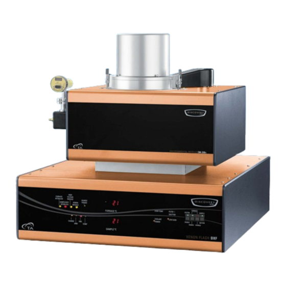
Detector Assembly, and the controller. Pulse Source Module The Discovery Xenon Flash (DXF) covers the most commonly needed cryogenic to 900°C temperatures with a range of Environmental Modules, and employs a High Speed Xenon-Pulse Delivery Source (HSXD). The reflective optic configuration effectively harnesses the power of a Xenon flash tube, and, with the aid of proprietary wave guides, delivers it to the sample inside the Environmental Module. - Page 14 Table 1: DXF Front Panel LED Indicators Indicator Function FURNACE INTERLOCK GREEN indicates that the EM is sitting correctly on top of the DXF. RED indicates that EM is sitting incorrectly and must be adjusted. GREEN indicates that the Detector Head is closed and ready SAMPLE/DETECTOR INTERLOCK for use, and that the detector is secured correctly to the EM.
- Page 15 Table 1: DXF Front Panel LED Indicators Indicator Function FURNACE DISABLE switch ON indicates one of the following: • The furnace is unable to heat • Heat to the furnace was stopped • Any of the conditions for enabling the furnace were vio- lated SAMPLE MOTION switch Not in use.
-
Page 16: Environmental Modules And Detector Assembly
Environmental Modules and Detector Assembly The Environmental Module includes a resistance-heated and liquid nitrogen cooled furnace, providing temperature control of the sample operation in dry air or inert gas, or in vacuum. The EM also includes a user-replaceable multi-sample tray holder (Autosampler), supporting a variety of sample sizes. and a con- tact detection system. -
Page 17: Instrument Specifications
Instrument Specifications The tables found below contain the technical specifications for the DXF and EM. Table 2: DXF 200+ System Technical Specifications Item/Area DXF 200+ Specifications Dimensions Depth 66.04 cm (26 in) Width 62.87 cm (24.75 in) Height 57.79 cm (22.75 in) Weight 83 kg (183 lbs) System supply voltage: 198–242 VAC (rated for 6A) -
Page 18: Chapter 2: Installing The Dxf System
• Performing calibrations It is strongly recommended that you have your DXF system installed by a TA Instruments Service Repre- sentative; call for an installation appointment when you receive your instrument. CAUTION: To avoid mistakes, read this entire chapter before you begin installation. -
Page 19: Choosing A Location
Choosing a Location Because of the sensitivity of DXF experiments, it is important to choose a location for the instrument using the following guidelines. The DXF system should be: • A temperature and humidity controlled area. • A clean, vibration-free environment. •... -
Page 20: Moving The Instrument
masse de l'instrument est correctement connectée à la masse de l'installation pour un fonctionne- ment sûr. WARNING: For safety, position the equipment in a manner that allows access to the power cord for emergency disconnection. AVERTISSEMENT: Par mesure de sécurité, placez l'équipement de sorte qu'il permette d'accéder facilement au cordon d'alimentation en cas de débranchement d'urgence. - Page 21 Place hands on the corners of the EM Place hands on the outside of the DXF feet Figure 4 Lifting the EM (top) and lifting the DXF (bottom). DXF Getting Started Guide Page 21...
-
Page 22: Connecting The Environmental Module To The Pulse Source Module
Connecting the Environmental Module to the Pulse Source Module NOTE: Refer to Appendix A: Connection Diagram for a diagram of all instrument connections. WARNING: Hand crush hazard is present. Do not place hands between the Environmental module and the DXF. AVERTISSEMENT: Un risque d'écrasement des mains est présent. -
Page 23: Dxf Back Panel
DXF Back Panel The DXF back panel has nine ports; the table below provides a description of the function of each port. Refer to Figure 6 for an illustration of rear connections. Ports not described and not labeled are not used. Table 4: DXF Back Panel Ports and Functions Port... - Page 24 EM Back Panel The EM back panel has 13 ports; the table below provides a description of the function of each port. Refer Figure 8 for an illustration of rear connections. Port Function DETECTOR PURGE GAS OUTLET Provides inert gas to EM Detector Assembly. PURGE GAS INLET Provides inert gas to the EM Furnace Core and Chamber Backfill.
- Page 25 DETECTOR CONTROL VACUUM GAUGE DETECTOR PURGE GAS OUTLET PURGE GAS INLET CRYOGENIC- COOLANT INLET EM COMM CRYOGENIC- COOLANT OUTLET SAMPLE CRYOGENIC VALVE CONTROL EM POWER INLET FURNACE TC EM CONTROL AUTOSAMPLER Figure 7 Environmental Module rear panel connections. DXF Getting Started Guide Page 25...
-
Page 26: Connecting The Environmental Module To The Pulse Source
Table 5: EM Side Panel Port Function PURGE FLOW CONTROL Controls the purge gas flow into the Furnace Core (sample area). CORE PURGE ON/OFF Turns ON and OFF the purge gas to the Furnace Core (sam- ple area). CHAMBER BACKFILL ON/OFF Turns on and off the purge gas backfill to the Furnace Cham- ber. -
Page 27: Connecting The Detector Cable To The Detector Head Assembly
Connect the power cable into the back of the DXF and into a power strip and then plug into a wall power outlet. Connecting the Detector Cable to the Detector Head Assembly Connect the DETECTOR cable to the connector on the back of the Detector Assembly and to the DETECTOR CONTROL connector on the back of the EM and the DETECTOR connector on the back of the DXF. -
Page 28: Connecting The Utilities
Setting Up the Vacuum System The vacuum system is an accessory available for purchase at TA Instruments. If you are not using a vac- uum system, close the valve with a blanking plate. -
Page 29: Connecting Cryogenic Cooling And Purge Gas Lines
Connecting Cryogenic Cooling and Purge Gas Lines Cryogenic Cooling Connect the end of the liquid nitrogen inlet hose Swagelok® fitting to the CRYOGENIC COOLANT INLET fitting on the back of the EM and connect the other end to the liquid port on the liquid nitrogen dewar. - Page 30 WARNING: Sample plate will be hot. Use caution when loading and unloading samples. Check the sample temperature on the front panel; 60°C and below is safe to handle. AVERTISSEMENT: la plaque d'échantillonnage sera chaude. Soyez prudent lors du chargement et du déchargement des échantillons. Vérifiez la tempéra- ture de l'échantillon sur le panneau avant;...
-
Page 31: Calibrating The Tray Position
Calibrating the Tray Position This calibration should be performed after the tray is installed or as needed. Open the software by double-clicking the FlashLine icon on the computer desktop. From the Setup menu, click Select Diagnostic Mode. From the Diagnostics menu, click Autosampler. Figure 13 Diagnostics menu. -
Page 32: Verifying The Tray Position Calibration
Click Start Tray Calibration and then click Yes. The tray moves to the Home position. Figure 15 Start Tray Calibration. Move position 1 of the tray (marked by a notch) so that the position 1 round opening on the tray aligns with the center of the shade. -
Page 33: Installing The Pins
Installing the Pins Remove the 4 screws on the Detector cover with a 9/64 hex wrench. Figure 16 Remove screws. Using a 7/64 hex wrench, remove the metal retaining plate screw and set the plate and screw aside. Figure 17 Remove the retaining plate. DXF Getting Started Guide Page 33... - Page 34 Using tweezers, remove the heat shield (two pieces). Figure 18 Using a 7/64 hex wrench, loosen the clamps that hold the Detector pins in place. Figure 19 Loosen clamps. Using a small flathead screwdriver, loosen the innermost screws that hold the lead for the detector pin. Figure 20 Loosen lead screws.
- Page 35 Carefully remove the pins from the box. Insert the pins, making sure to match the leads on the pin with the leads on the terminal blocks. Orient the detector pins as shown in the image below (left). Red lead Terminal block Black lead...
- Page 36 Using a small flathead screwdriver, lock the pin leads into place. Figure 22 Lock the pin leads. 10 Verify pin orientation (see Figure 21). 11 Carefully insert the two pieces of the white heat shield, placing the half with the holes to the front. Figure 23 Install the heat shield.
- Page 37 12 Place the retaining plate around the heat shield and tighten the screw using a 7/64 hex wrench. Make sure that the pins are not touching the heat shield. Figure 24 Install the retaining plate. 13 Place the Detector Head cover back on and secure the four screws with a 9/64 hex wrench. DXF Getting Started Guide Page 37...
-
Page 38: Calibrating Pin Height
Calibrating Pin Height This calibration should be performed after tray calibration and installing the pins and before running tests or loading samples. Open the software by double-clicking the FlashLine icon on the computer desktop. From the Setup menu, click Set Diagnostic Mode. From the Diagnostics menu, click Autosampler. - Page 39 From the Autosampler window, click Start Probe Calibration, and then click Yes to start this calibration. Figure 26 Start Probe Calibration. DXF Getting Started Guide Page 39...
- Page 40 Adjust the pin height using the Pins Up and Pins Down buttons. “Sm,” “Med,” and “Lrg” indicate the size of the incremental movements of the pins (Figure 27). The pins should be adjusted until a piece of paper fits in the gap between the pin on the brass block and lift carriage (Figure 28).
- Page 41 Click the Save button located below the Pins Up and Down buttons to save the calibration. Click Pins Park. Verifying Pin Height 10 From the Diagnostics menu, click Autosampler. (Figure 11 The Autosampler window displays (Figure 27). Enter 10 mm in the Set Sample Thickness field. 12 Enter 0 in the Set Spring Tension Offset field.
-
Page 42: Chapter 3: Operating The Dxf
Chapter 3: Operating the DXF Using the DXF All of your DXF experiments will have the following general outline. In some cases, not all of these steps will be performed. The majority of these steps are performed using the instrument control software. The instructions needed to perform these actions can be found in the online help in the instrument control software;... -
Page 43: Startup And Shutdown Procedures
Startup and Shutdown Procedures Starting the DXF System The power switch is located on the back panel of the DXF. The power switch is used to turn the DXF sys- tem on and off. To power on the system: Check all connections between the DXF, the Environmental Module, the Detector Assembly, and the controller. -
Page 44: Running A Discovery Dxf Experiment
Running a Discovery DXF Experiment Preparing the Sample The method is applicable for testing homogeneous, solid, and opaque materials. However, in real life, materials greatly deviating from the above can be tested with special sample preparations, precautions, and analytical corrections. It is incumbent on the user to ascertain if a new material can be tested in an “as received form”... -
Page 45: Transparent Or Translucent Materials
Transparent or Translucent Materials The method requires that all of the energy from the flash be absorbed on one face of the sample. For mate- rials that are transparent or translucent, the energy from the light pulse will travel to different depths in the sample (depending on opacity) or may completely pass through in a completely transparent sample. - Page 46 Applying Graphite Spray The following is the procedure for coating samples with graphite spray: Place the samples onto a plain sheet of paper. Locate them in one line close to each other. Using a heat gun, gently warm the samples. Hold the aerosol can of graphite spray approximately 8–10 inches from the samples.
-
Page 47: Loading And Unloading The Sample
Loading and Unloading the Sample Unlock the latch on both sides of the Detector Assembly and raise the Assembly up away from the EM. Then swing the Detector Head to the left, away from the furnace. Figure 29 Raise the Detector Head. WARNING: Sample plate will be hot. - Page 48 After all samples have been loaded, carefully close the Detector Assembly back into the EM (position your right hand as shown in the image below to ensure the measurement head is closed safely) and secure the latches. Note that the Detector Head is difficult to lower when pressing down only on the Detector Head.
-
Page 49: Preparing The Instrument
Preparing the Instrument Evacuating the System Some systems are equipped with vacuum capabilities; all are equipped with purge capabilities. Purge gas exits through the anti-siphon exit port assembly. CAUTION: Never place any type of valve between the EM exhaust and the anti-siphon exit port assembly. - Page 50 Back-fill with Purge Gas Turn off the vacuum pump. Follow the procedure for Vacuum and Purge Operation. Enable the core purge gas flow to the EM chamber. Monitor the flow using the anti-siphon exit port assembly. Flow should be continuous, roughly 4–5 bubbles/second.
-
Page 51: Starting An Experiment
Starting an Experiment Access the instrument control software to create or choose the test procedure as well as enter sample and instrument information through the instrument control software. To open the software, double-click the FlashLine icon on the computer desktop. From the Operation menu, click Startup Information. - Page 52 Enter the test parameters and then click Start Test. Figure 34 Test Information window. Top section of the Test Information window: • Test Title: The entered information is added to the test information file for future reference. • Test ID: The name of the test saved in the Instrument Data folder. The Test ID number advances automatically.
- Page 53 • Sample ID: Enter Sample identification for each position. • Sample Title: Enter a sample description text for each position. • Thickness (cm): Enter the sample thickness for each position. Diameter (cm): Set automatically based on the selected tray. Verify that it matches the tested sam- •...
-
Page 54: Stopping An Experiment
• Start Test: Once all of the above fields are filled and the system is ready for test, click the Start Test button to start the test process. Follow the window instructions for selecting relevant options and for enabling the system and furnace. Stopping an Experiment If for some reason you need to discontinue the experiment, you can stop it at any point by clicking the Stop Test icon from the FlashLine application screen. -
Page 55: Chapter 4: Maintaining The Dxf/Em
The primary maintenance procedures described in this chapter are the customer’s responsibility. Any fur- ther maintenance should be performed by a representative of TA Instruments or other qualified service per- sonnel. Consult the online documentation installed with the instrument control software for further information. -
Page 56: Recommended Cleaning Supplies
Recommended Cleaning Supplies • Compressed air duster can or dry nitrogen from the bottle which supply the purge gas for instrument- with flexible plastic, movable/bend nozzle (never use compress air from industrial compressor lines; it contains a large amount of water and residual oil) •... -
Page 57: Maintenance Procedures
Maintenance Procedures Cleaning the Light Pipe Assembly NOTE: The sample is directly above the Xenon pulse distribution light pipe. It is therefore important to protect the light pipe from dirt and possible damage. Periodic cleaning of the top surface of the light pipe is recommended. -
Page 58: Cleaning The Detector Pins (Dxf 200+ Only)
NOTE: Take care not to scratch the surface of the light pipe. Reassemble the parts back into EM module. Clean the Xenon Lamp Assembly Optics Using the compress air duster, clean the exit window to remove any possible dust that may be contaminating the window. - Page 59 Lift the Detector Assembly up. Figure 40 Detector raised. From the FlashLine software Test Information window, click Pins/Autosampler Control. Figure 41 Access pins and Autosampler control functions. DXF Getting Started Guide Page 59...
- Page 60 The Pins/Autosampler Control window displays. Click Pins Clean to lower the pins. Figure 42 Pins Park. Check the pin shape. The slightly pointy shape of the pin can dent or even penetrate the sample. The tip should be slightly flat. Figure 43 Pin shape.
- Page 61 Put the Detector back in place, lowering it back into the sample area. Note that the Detector Head is difficult to lower when pressing down only on the Detector Head. Instead, press down the Detector Head while simultaneously pressing down on the Detector arm, as shown below. Figure 44 Lowering the Detector Head.
-
Page 62: Conditioning The Furnace
Conditioning the Furnace Vacuum performance dwindles during off time due to moisture absorption into the insulation and contami- nation of the furnace. To prevent this, the furnace should be kept closed and under positive pressure of inert gas atmosphere. Regardless, after a period of time, an unused furnace may require conditioning in order to restore vacuum performance. - Page 63 From the Diagnostics menu, select Temperature Controller. A Temperature Controller window displays. Figure 47 Temperature Controller window. Click Initialize. Click System Enable both from the Temperature Controller window and on the front panel of the instrument. Click Furnace Enable both from the Temperature Controller window and on the front panel of the instrument.
-
Page 64: Replacement Parts
Replacement Parts Replacement parts for the DXF are listed below. Refer to the table below when ordering parts. Part Number Description 202315.001 Moderate Vacuum Module: large capacity two-stage mechanical vacuum pump 853024.901 In-Plane Test Kit: fixture used to mask the energy pulse for thermal diffusivity determination in the X-Y plane. -
Page 65: Appendix A: Connection Diagram
Appendix A: Connection Diagram DXF Getting Started Guide Page 65...
Need help?
Do you have a question about the DISCOVERY XENON FLASH and is the answer not in the manual?
Questions and answers