Table of Contents
Advertisement
Quick Links
Advertisement
Chapters
Table of Contents

Related Manuals for TA Instruments DSC Autosampler CE


Summary of Contents for TA Instruments DSC Autosampler CE
- Page 1 109 Lukens Drive New Castle, DE 19720 Thermal Analysis & Rheology UBSIDIARY OF ATERS ORPORATION Autosampler Operator’s Manual PN 825616.001 Rev. B (Text and Binder) PN 825616.002 Rev. B (Text Only) Issued November 1999 TA I DSC A NSTRUMENTS UTOSAMPLER...
- Page 2 Notice TA I DSC A NSTRUMENTS UTOSAMPLER...
- Page 3 Table of Contents xiii ........xiv CHAPTER 1: Introducing the DSC Autosampler CE TA I DSC A NSTRUMENTS UTOSAMPLER...
- Page 4 Table of Contents (continued) CHAPTER 2: Preparing the Autosampler CE CHAPTER 3: Using the Autosampler CE in Manual Mode TA I DSC A NSTRUMENTS UTOSAMPLER...
- Page 5 Table of Contents (continued) CHAPTER 4: Calibrating the Autosampler CE TA I DSC A NSTRUMENTS UTOSAMPLER...
- Page 6 Table of Contents (continued) CHAPTER 5: Preparing Samples TA I DSC A NSTRUMENTS UTOSAMPLER...
- Page 7 Table of Contents (continued) CHAPTER 6: Diagnostics TA I DSC A NSTRUMENTS UTOSAMPLER...
- Page 8 Table of Contents (continued) Appendix A: Parts Lists & Ordering Information Index viii TA I DSC A NSTRUMENTS UTOSAMPLER...
- Page 9 Notes, Cautions, and Warnings Highlights important information about equip- NOTE: ment or procedures. t CAUTION: Emphasizes a procedure that may damage equipment or cause loss of data if not followed correctly. Indicates a procedure that may be hazardous to the operator or the environment if not WARNING followed correctly.
- Page 10 Help Lines To TA Instruments TA I DSC A NSTRUMENTS UTOSAMPLER...
- Page 11 Safety CE Compliance Safety: Emissions: Immunity: TA I DSC A NSTRUMENTS UTOSAMPLER...
- Page 12 Autosampler CE Safety Labels Operation Safety TA I DSC A NSTRUMENTS UTOSAMPLER...
- Page 13 Operator’s Manual LNCA Operator’s Manual Lifting the Instrument Use two people to lift and/or carry the WARNING instrument. The instrument is too heavy for one person to handle safely. TA I DSC A xiii NSTRUMENTS UTOSAMPLER...
- Page 14 Using This Manual Chapter 1 Chapter 2 Chapter 3 Chapter 4 Chapter 5 TA I DSC A NSTRUMENTS UTOSAMPLER...
- Page 15 Using This Manual (continued) Chapter 6 Appendix Index TA I DSC A NSTRUMENTS UTOSAMPLER...
- Page 16 TA I DSC A NSTRUMENTS UTOSAMPLER...
-
Page 17: Table Of Contents
CHAPTER 1: Introducing the DSC Autosampler CE Overview ............ 1-3 General Features ........1-4 Relationship to the System ......1-7 Description ..........1-9 The Turret Assembly ......1-10 The Gripper Fingers ......1-11 The Sample Tray ....... 1-12 The Keypad ........1-13 The Display ........ - Page 18 Introducing the DSC Autosampler CE 1–2 TA I DSC A NSTRUMENTS UTOSAMPLER...
-
Page 19: Overview
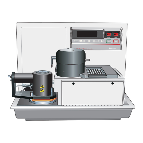
Overview Overview Your TA Instruments DSC Autosampler CE is a four-axis robotic device that automatically loads sample and reference pans to and from the Differential Scanning Calorimeter (DSC) thermal analysis instrument. The Autosampler CE will detect the presence of a single or dual sample cell and adjust its actions and displays accord- ingly. -
Page 20: General Features
Introducing the DSC Autosampler CE General Features The following features make the DSC Autosam- pler CE a unique and flexible tool: • The Autosampler CE makes decisions on the basis of current system status, operator- directed parameters, and computer-directed instructions. - Page 21 General Features operations for you. The Autosampler CE has no effect on any other instrument connected to the controller. You can also connect two or more Autosampler CEs to the controller to work with two or more DSCs. • The Autosampler CE can change both reference and sample pans.
- Page 22 Introducing the DSC Autosampler CE • The Autosampler CE can be used with the full range of thermal analysis temperature profiles currently used in manual experiments (depending upon the cooling accessory installed). • The AS run sequence ensures that the DSC...
-
Page 23: Relationship To The System
Relationship to the System Relationship to the System The DSC Autosampler CE is part of a system consisting of the TA Instruments controller and a 2920 DSC instrument (see Figure 1.1). DSC with the AUTOSAMPLER CE CONTROLLER GPIB CELL 15 TO 120 PSI... - Page 24 Introducing the DSC Autosampler CE DSC with the AUTOSAMPLER CE GPIB CELL 15 TO 120 PSI LAB AIR LNCA Serial Interface LNCA Coolant Line ELECTRICAL CABLE PNEUMATIC TUBE Figure 1.2 Autosampler CE System with LNCA DSC with the AUTOSAMPLER CE...
-
Page 25: Description
Description Description The DSC Autosampler CE consists of a turret assembly, a sample tray, an operator’s keypad, and a display screen in an assembly that mounts on the instrument (see Figures 1.4 and 1.5). NOTE: The functions of the DSC instrument keypad and display will not change when the Autosampler CE is mounted. -
Page 26: The Turret Assembly
Introducing the DSC Autosampler CE The Turret Assembly Three stepper motors move the turret assembly through its three major axes of motion (see Figure 1.6). Rotary stepper motors rotate the turret assembly in the clockwise or counter- clockwise direction (along the q-axis) and move the turret arm in and out (along the r-axis). -
Page 27: The Gripper Fingers
They are made of conductive stainless steel and are controlled by tactile-feedback sensors that detect improperly gripped or dropped objects. Figure 1.7 The DSC Autosampler CE Gripper Fingers TA I DSC A 1–11 NSTRUMENTS... -
Page 28: The Sample Tray
Introducing the DSC Autosampler CE The Sample Tray The sample tray is constructed of anodized aluminum and has a clear acrylic cover (see Figure 1.8). It holds up to 62 pans. Chapter 5 describes how to set up the sample tray. -
Page 29: The Keypad
Description The Keypad To access the DSC Autosampler CE keypad for manual operations, open the keypad cover by loosening the captive thumbscrews in the cover (see Figure 1.9) and tilting the cover down. When you are ready to start a method, close the... - Page 30 Introducing the DSC Autosampler CE The DSC Autosampler CE keypad operates independently of the DSC keypad (see your DSC Operator's Manual for details on its keypad). The Autosampler CE keypad consists of four types of keys (see Figure 1.10): •...
- Page 31 The DSC Autosampler CE keys are explained in alphabetical order in Table 1.1 (pages 1-16 to 1- 19). The motion keys are grouped into one entry entitled “The Motion Keys.”...
- Page 32 Introducing the DSC Autosampler CE NOTE: Except for the HALT and RESET SAMPLER keys, the Autosampler CE keypad is operable only when the Autosampler CE is in manual mode (see Chapter 3). Table 1.1 The Autosampler CE Keys Description Enables you to calibrate...
- Page 33 Description Table 1.1 (continued) Description ESCAPE/ by pressing the CLEAR ESCAPE/CLEAR key. In this case, the (cont'd) ESCAPE function is active. • When numeric input is requested (indicated by blinking cursor), you can clear the current entry by pressing the ES- CAPE/CLEAR key.
- Page 34 Introducing the DSC Autosampler CE Table 1.1 The Autosampler CE Keys (continued) Description Loads pans from the LOAD Autosampler CE tray to the DSC cell or unloads pans from the cell and returns them to the tray (see Chapter 3).
- Page 35 Description Table 1.1 (continued) Description Enables you to change the SPEED speed of manual Auto- sampler CE movement (see Chapter 3). In automatic mode, the Autosampler CE operates at preselected speeds depending on the function being performed. Runs diagnostic tests to TEST check the Autosampler CE’s calibration, sensors,...
-
Page 36: The Display
Introducing the DSC Autosampler CE The Display The Autosampler CE has a 32-character liquid crystal display (see Figure 1.11). The screen displays a blinking cursor whenever user input is requested. The Autosampler CE's display is independent of the DSC instrument display (refer to the DSC Operator's Manual for details on the instrument display). -
Page 37: System And Equipment Requirements
Description System and Equipment Requirements The DSC Autosampler CE requires the following equipment: • A TA Instruments controller. • A source of compressed, dry air (15 psi minimum, 120 psi maximum) for adjusting the DSC cell temperature between runs. •... -
Page 38: Terminology
Introducing the DSC Autosampler CE Terminology The terms manual and automatic are used throughout this book to describe the DSC Autosampler CE’s two modes of operation. In manual mode, the Autosampler CE does not need to communicate with the controller and is controlled directly through its own keypad. -
Page 39: Axis Terms
Terminology When the Autosampler CE is in automatic mode, you can use the controller keyboard to: • Input experimental parameters • Create, edit, and execute Autosampler CE run sequences that automatically load samples, run methods, and unload samples at the end of the experiment •... - Page 40 Introducing the DSC Autosampler CE Rotational movement (clockwise and counter- clockwise) occurs along the q-axis (theta-axis): Figure 1.13 The q-Axis Upward and downward movement occurs along the z-axis: Figure 1.14 The Z-Axis 1–24 TA I DSC A NSTRUMENTS UTOSAMPLER...
-
Page 41: Testing Terminology
Terminology Testing Terminology The terms AS (Autosampler CE) run sequence and run refer to the experiments that you set up to control the Autosampler CE motion and running of thermal analysis methods. A run is a single TA experiment that consists of the following events: •... - Page 42 Introducing the DSC Autosampler CE 1–26 TA I DSC A NSTRUMENTS UTOSAMPLER...
- Page 43 CHAPTER 2: Preparing the Autosampler CE Introduction ..........2-3 Preparing for Operation ......2-4 Connecting the Heat Exchanger Cable ......2-4 Installing the Autosampler CE Lids ..2-5 Installing the Dust Cover ...... 2-6 After Preparation ........2-7 TA I DSC A 2–1 NSTRUMENTS...
- Page 44 Preparing the Autosampler CE 2–2 TA I DSC A NSTRUMENTS UTOSAMPLER...
-
Page 45: Introduction
Introduction Introduction When you purchase your Autosampler CE, it will be unpacked and set up by a TA Instruments representative. This section contains certain procedures that need to be performed occasion- ally as part of the Autosampler CE setup. Once you have completed setting up your... -
Page 46: Preparing For Operation
Preparing the Autosampler CE Preparing for Operation Connecting the Heat Exchanger Cable When you place the LNCA heat exchanger on the DSC instrument with an Autosampler CE, you need to connect the heat exchanger cable to the instrument. (The LNCA Operator’s Manual contains more details on installing the heat exchanger.) Connect the heat exchanger as follows:... -
Page 47: Installing The Autosampler Ce Lids
Preparing for Operation Installing the Autosampler CE Lids When your Autosampler CE is unpacked, you will find three different lids that are to be used when a sample is placed into the cell. The lids are different sizes and made of different materi- als. -
Page 48: Installing The Dust Cover
Preparing the Autosampler CE Installing the Dust Cover The plastic dust cover that comes with the Autosampler CE should be in place whenever you leave the Autosampler CE to run a series of samples. This will prevent dust and dirt from interfering with your experiments. -
Page 49: After Preparation
After Preparation After Preparation Now that your Autosampler CE has been completely installed and set up, you will need to calibrate it so that it will properly pick up and deposit pans. Calibration is done using the manual mode functions, which are described in the next chapter. - Page 50 Preparing the Autosampler CE 2–8 TA I DSC A NSTRUMENTS UTOSAMPLER...
- Page 51 CHAPTER 3: Using the Autosampler CE in Manual Mode Overview ............ 3-3 Starting the Autosampler CE ...... 3-4 Switching from Automatic to Manual Mode ........3-5 Understanding the Confidence Tests ........3-6 Moving the Turret Assembly ...... 3-7 The Motion Keys ........3-8 Changing the Motor Speed ....
- Page 52 Using the Autosampler CE in the Manual Mode 3–2 TA I DSC A NSTRUMENTS UTOSAMPLER...
-
Page 53: Overview
Autosampler CE in manual mode. (See page 1– 22 for an explanation of the manual and auto- matic modes.) When the DSC Autosampler CE is in manual mode, it can be controlled by the Autosampler CE keypad. This chapter describes the following manual mode procedures: •... -
Page 54: Starting The Autosampler Ce
Turn on the POWER switch on the DSC Autosampler CE. The Autosampler CE displays: Confidence Test Version x.x then: Copyright 1986 TA Instruments, Inc See page 3–6 for a discussion of the confidence tests. When the confidence tests are complete, the display reads: Automatic Mode Offline The Autosampler CE will go into automatic mode upon initial startup. -
Page 55: Switching From Automatic To Manual Mode
Starting the Autosampler CE Switching from Automatic to Manual Mode 1. Access the Autosampler CE keypad by loosening the captive thumbscrews on the keypad cover and tilting the cover down. 2. Press the HALT key on the Autosampler CE keypad. The display reads: Automatic Mode Halted 3. -
Page 56: Understanding The Confidence Tests
Using the Autosampler CE in the Manual Mode Understanding the Confidence Tests At power-up, the Autosampler CE runs a set of 13 confidence tests to check its internal electron- ics and memory, display, keypad, motors, and sensors. If a system that is critical to continued operation fails, the confidence tests stop and the Autosampler CE shuts down with an error message on the display, unless the display itself... -
Page 57: Moving The Turret Assembly
You can change the speed of the turret motion with the SPEED key. The motion and SPEED keys are explained on the following pages. Figure 3.1 The DSC Autosampler CE Motion Keys TA I DSC A 3–7... -
Page 58: The Motion Keys
Using the Autosampler CE in the Manual Mode The Motion Keys (Rotate Clockwise) ROTATE Moves the turret clock- wise until the clockwise limit is reached. (Rotate Counter- ROTATE clockwise) Moves the turret counterclockwise until the counterclock- wise limit is reached. Raises the turret until the RAISE upper limit is reached. -
Page 59: Changing The Motor Speed
Moving the Turret Assembly Changing the Motor Speed The SPEED key enables you to change the speed of manual Autosampler CE movement. The speed you select applies only to the motion keys; when the Autosampler CE is executing commands from the controller or one of the Autosampler CE command keys (LOAD, LIDS), the speed is preset and is not affected by your selection. -
Page 60: Covering And Uncovering The Dsc Cell
Using the Autosampler CE in the Manual Mode Covering and Uncovering the DSC Cell The LIDS key covers or uncovers the DSC cell when the Autosampler CE is in manual mode. t CAUTION: Do not remove lids exceeding 100 C from the DSC cell;... -
Page 61: Loading And Unloading Sample Pans
Loading and Unloading Pans Loading and Unloading Sample Pans The LOAD key loads and unloads sample pans to and from the DSC cell when the Autosampler CE is in manual mode. If the lids are on the DSC cell, the Autosampler CE first removes them, then performs the load or unload function. - Page 62 Using the Autosampler CE in the Manual Mode 4. Select a cell position (reference or sample) by pressing a numeric key, then pressing ENTER. You are then prompted to select the tray position to load from: Sample Pan Number ? 1 5.
-
Page 63: Unloading Pans
Loading and Unloading Pans Unloading Pans The LOAD key unloads pans that have been loaded in automatic mode, manual mode, or with tweezers. The Autosampler CE does not keep track of the NOTE: pans in the sample tray. Be careful not to unload a pan on top of another pan in the tray. - Page 64 Using the Autosampler CE in the Manual Mode 5. Select a tray position: • Press ENTER to select sample pan 0, and the Autosampler CE will unload the selected pan back to the tray position from which it was originally loaded. •...
-
Page 65: Stopping The Autosampler Ce
Stopping the Autosampler CE Stopping the Autosampler CE Three keys on the Autosampler CE keypad enable you to suspend and resume Autosampler CE motion: the HALT key, the RESUME key, and the RESET SAMPLER key. The HALT Key The HALT key affects only the motion of the Autosampler CE turret assembly;... -
Page 66: The Resume Key
Autosampler CE is returned to the home position (see Figure 3.2). Figure 3.2 The DSC Autosampler CE in Home Position When you press the RESET SAMPLER key, the Autosampler CE displays:... - Page 67 Stopping the Autosampler CE To execute the Reset Sampler command, press ENTER. To cancel the Reset Sampler command and return to the previous operation, press ESCAPE/CLEAR. If you press ENTER to continue the reset, the display shows: Manual Mode Resetting When the Autosampler CE reaches home position, the display displays: Manual Mode...
-
Page 68: Conditions When Resetting
Using the Autosampler CE in the Manual Mode Conditions When Resetting The Autosampler CE assumes that the DSC cell is empty when you press RESET SAMPLER, so you should check that this is true whenever you press this key. If there are any pans in the cell after you press RESET SAMPLER, you must remove them manually with tweezers or the Autosampler CE motion keys. - Page 69 CHAPTER 4: Calibrating the Autosampler CE Overview ............ 4-3 Precalibration Checklist ......4-8 Performing the Calibration ......4-9 Calibrating the Cell Lid Positions ..4-11 Calibrating the Cell Pan Positions..4-15 Calibrating the Lid Storage Positions ........ 4-21 Calibrating the Sample Tray ....4-25 Checking Your Calibration ......
- Page 70 Calibrating the Autosampler CE 4–2 TA I DSC A NSTRUMENTS UTOSAMPLER...
-
Page 71: Overview
Overview Overview NOTE: The calibration procedures described in this chapter are critical to proper operation of the Autosampler CE. In order for the Autosampler CE to accurately pick up, load, and unload sample pans, it must be correctly calibrated. There are four different calibration procedures for the Autosampler CE: •... - Page 72 Calibrating the Autosampler CE Table 4.1 Autosampler CE Calibration Position Screen Display Autosampler CE Position The small, silver lid’s position on Calibrate/Verify the DSC cell. Lid #1 Cell The medium-sized, stainless-steel Calibrate/Verify lid’s position on the DSC cell. Lid #2 Cell The large, aluminum lid’s position on Calibrate/Verify the DSC cell.
- Page 73 Overview Table 4.1 (continued) Screen Display Autosampler CE Position The dimple in the DSC cell where Calibrate/Verify the reference pan is placed (the Cell Ref. Pos. rear position). The dimple in a DSC cell where the Calibrate/Verify sample pan is placed. (For dual Sample Pos.
- Page 74 Calibrating the Autosampler CE Table 4.1 Autosampler CE Calibration Position (continued) Screen Display Autosampler CE Position Calibrate/Verify The medium-sized, stainless-steel Lid #2 Storage lid’s storage position. The large, aluminum lid’s storage Calibrate/Verify position. Lid #3 Storage (table continued) 4–6 TA I DSC A NSTRUMENTS UTOSAMPLER...
- Page 75 Overview Table 4.1 (continued) Screen Display Autosampler CE Position Position 1 on the sample tray. Calibrate/Verify Tray Pos. #1 Position 11 on the sample tray. Calibrate/Verify Tray Pos. #11 Position 59 on the sample tray. Calibrate/Verify Tray Pos. #59 TA I DSC A 4–7 NSTRUMENTS...
-
Page 76: Precalibration Checklist
Calibrating the Autosampler CE Precalibration Checklist Use the checklist below to make sure your Autosampler CE system is set up properly and ready to be calibrated. Ensure that: You have two properly crimped, empty pans to use in the calibration procedure (see Chapter 5 for pan crimping instructions). -
Page 77: Performing The Calibration
Performing the Calibration Performing the Calibration Please read the following cautions and notes before calibrating the Autosampler CE. They are numbered for easy reference. CAUTIONS t CAUTION: 1) Each time you select the Verify function or move the turret with the LIDS or LOAD key, hold your finger over the HALT key so that you can stop the Autosampler CE if it looks as if the grippers are going to run into something. - Page 78 Calibrating the Autosampler CE NOTES 1) Calibrate the Autosampler CE in the order NOTE: shown in this manual. 2) The Autosampler CE must be in manual NOTE: mode during calibration (see Chapter 3). NOTE: 3) You should be familiar with how the motion keys work before you calibrate the Autosampler CE.
-
Page 79: Calibrating The Cell Lid Positions
Performing the Calibration Calibrating the Cell Lid Positions Because each DSC cell is custom made, the cell lid positions cannot be calibrated at the factory and must be calibrated on newly installed Autosampler CEs. 1. Access the Autosampler CE keypad by loosening the captive thumbscrews on the keypad cover and tilting the cover down. - Page 80 Calibrating the Autosampler CE GRIPPERS ALL FOUR FINGERS SIDE VIEW SHOULD CONTACT THE LID IN OPEN AT THE POSITION, SAME TIME FINGERS WHEN YOU SHOULD BE PRESS THE EQUIDISTANT GRIP KEY. FROM THE KNOB ON THE LID. TOP VIEW Figure 4.1 Calibrating a Cell Lid Position 8.
- Page 81 Performing the Calibration 10. Select option 2 (Store) to store the calibra- tion position (press the 2 key, then press ENTER). The screen displays: Lid #1 Cell Calibrated 11. Release the lid (press the RELEASE key). Press RESET SAMPLER and ENTER to bring the Autosampler CE to the home position.
- Page 82 Calibrating the Autosampler CE Steps 8 and 11: Calibrate/Verify Lid #2 Cell Calibrate/Verify Lid #3 Cell Step 10: Lid #2 Cell Calibrated Lid #3 Cell Calibrated 16. When you have calibrated all three cell lid positions, use the LIDS key to return the lids to their storage positions (select option 1 [Uncover]).
-
Page 83: Calibrating The Cell Pan Positions
Performing the Calibration Calibrating the Cell Pan Positions Because each DSC cell is custom made, the cell pan positions cannot be calibrated at the factory and must be calibrated on newly installed Autosampler CEs. 1. Access the Autosampler CE keypad by loosening the captive thumbscrews on the keypad cover and tilting the cover down. - Page 84 Calibrating the Autosampler CE 7. Select tray position 1 by pressing ENTER. The Autosampler CE picks up the pan in tray position 1 and begins moving toward the cell. 8. Press ESCAPE/CLEAR when the Auto- sampler CE reaches the DSC cell area. 9.
- Page 85 Performing the Calibration 10. When you are satisfied that the pan is properly positioned, press the CALIBRATE key repeatedly until you see the correct cell pan position on the display: Calibrate/Verify Cell Ref. Pos. 11. Press ENTER. The screen displays: Verify (1) or Store (2) ? 1 12.
- Page 86 Calibrating the Autosampler CE 16. When the turret stops moving, close and open the grippers again and check your calibration against the criteria in Figure 4.2. Remember to release the pan. If the position is correctly calibrated, go on to step 17. If it is not, repeat steps 4 through 16.
- Page 87 Performing the Calibration 23. When you are satisfied that the pan is properly positioned, press the CALIBRATE key repeatedly until you see the correct cell pan position on the display: Calibrate/Verify Sample Pos. 24. Press ENTER. The screen displays: Verify (1) or Store (2) ? 1 25.
- Page 88 Calibrating the Autosampler CE 28. Press ENTER to select default option 1 (Verify). 29. When the turret stops moving, close and open the grippers again and check your calibration against the criteria in Figure 4.2. Remember to release the pan and raise the turret out of the cell with the RAISE key.
-
Page 89: Calibrating The Lid Storage Positions
Performing the Calibration Calibrating the Lid Storage Positions To calibrate the lid storage positions, follow these steps: 1. Access the Autosampler CE keypad by loosening the captive thumbscrews on the keypad cover and tilting the cover down. 2. Press RESET SAMPLER and ENTER to bring the Autosampler CE to home position. - Page 90 Calibrating the Autosampler CE ALL FOUR FINGERS SHOULD CONTACT GRIPPERS IN OPEN POSITION, THE LID AT THE FINGERS SHOULD BE SAME TIME WHEN EQUIDISTANT FROM YOU PRESS THE THE KNOB ON GRIP KEY. THE LID. SIDE VIEW TOP VIEW Figure 4.3 Calibrating a Lid Storage Position 5.
- Page 91 Performing the Calibration The screen displays: Lid #1 Storage Calibrated 8. Release the lid (press the RELEASE key). Press RESET SAMPLER and ENTER to bring the Autosampler CE to the home position. Press the CALIBRATE key until the correct cell lid position is on the display: Calibrate/Verify Lid #1 Storage 9.
- Page 92 Calibrating the Autosampler CE Steps 5 and 8: Calibrate/Verify Lid #2 Storage Calibrate/Verify Lid #3 Storage Step 7: Lid #2 Storage Calibrated Lid #3 Storage Calibrated 13. Press ESCAPE/CLEAR to exit the calibra- tion procedure. NOTE: When you have finished using the Autosampler CE keypad, remember to close the keypad cover and finger-tighten the thumbscrews before starting a method.
-
Page 93: Calibrating The Sample Tray
Performing the Calibration Calibrating the Sample Tray To calibrate the sample tray positions, use the following procedures: NOTE: The Autosampler CE uses the calibrated tray positions 1, 11, and 59 to calculate all other tray positions. Be sure to verify each of these positions as described here. - Page 94 Calibrating the Autosampler CE GRIPPERS SAMPLE TRAY PEDESTAL SIDE VIEW ALL FOUR FINGERS SHOULD CONTACT THE PAN AT THE SAME TIME WHEN YOU PRESS THE GRIP IN OPEN POSITION, KEY. FINGERS SHOULD BE EQUIDISTANT FROM THE PAN. TOP VIEW Figure 4.4 Calibrating a Tray Position 6.
- Page 95 Performing the Calibration 8. Select option 2 (Store) to store the calibra- tion position (press the 2 key, then press ENTER). The screen displays: Tray Pos. #1 Calibrated 9. Release the pan (press the RELEASE key). Press RESET SAMPLER and ENTER to bring the Autosampler CE to the home position.
- Page 96 Calibrating the Autosampler CE Steps 6 and 9: Calibrate/Verify Tray Pos. #11 Calibrate/Verify Tray Pos. #59 Step 8: Tray Pos. #11 Calibrated Tray Pos. #59 Calibrated 14. Press ESCAPE/CLEAR to exit the calibra- tion procedure. NOTE: When you have finished using the Autosampler CE keypad, remember to close the keypad cover and finger-tighten the thumbscrews before starting a method.
-
Page 97: Checking Your Calibration
Checking Your Calibration Checking Your Calibration This section recommends three methods to check the accuracy of your Autosampler CE calibrations: • The LOAD/LIDS test • The Verify test • The Cycle Pans test. We recommend that you use the LOAD/LIDS test to check your first calibration. -
Page 98: The Load/Lids Test
Calibrating the Autosampler CE The LOAD/LIDS Test The LOAD/LIDS test is recommended for comprehensive testing of all calibration positions. To access the Autosampler CE keypad, loosen the captive thumbscrews on the keypad cover, and tilt the cover down. Step A: Use the LOAD key to test the Autosampler CE’s ability to load and unload pans from the tray to the DSC cell. - Page 99 Checking Your Calibration The screen displays: Sample Pan Number ? 1 6. Select tray position 6 (press the 6 key, then press ENTER). The Autosampler CE loads the pan in tray position 6 into the cell refer- ence position. 7. Press the LOAD key again. 8.
- Page 100 Calibrating the Autosampler CE 15. Press the LOAD key again. The screen displays: Load (1) or Unload (2) ? 1 16. Select option 2 (Unload) by pressing the 2 key, then pressing ENTER. The screen displays: Unload Ref(1) or Sample (2) ? 1 17.
- Page 101 Checking Your Calibration Step B: Use the LIDS key to test the Autosampler CE’s ability to cover the DSC cell. 1. Press RESET SAMPLER and ENTER to bring the Autosampler CE to home position. 2. Press the LIDS key. The Autosampler CE screen displays: Uncover (1) or Cover (2) ? 1...
-
Page 102: The Verify Test
Calibrating the Autosampler CE The Verify Test The Verify function is best for testing individual pan or lid positions; perform it as follows: 1. Access the Autosampler CE keypad by loosening the captive thumbscrews on the keypad cover and tilting the cover down. 2. -
Page 103: The Cycle Pans Test
Checking Your Calibration The Cycle Pans Test The Cycle Pans test exercises all of the Auto- sampler CE’s loading and unloading functions, but requires only a few simple keystrokes. It is recommended as a double check after the LOAD/LIDS test or as a quick verification for experienced users. - Page 104 Calibrating the Autosampler CE 6. Allow the Autosampler CE to complete at least one full cycle of the test: • Two pans are removed from their tray positions and placed in the cell. • The lids are placed on the cell. •...
- Page 105 CHAPTER 5: Preparing Samples Overview ............ 5-3 Installing the Crimping Die ......5-4 Setting Up the Sample Tray ......5-9 Autosampler CE Run Capacity... 5-10 Reuse of Pans ........5-11 Order of Runs ........5-12 Pan Metal and Type ......5-13 Preparing Sample Pans ......
- Page 106 Preparing Samples 5–2 TA I DSC A NSTRUMENTS UTOSAMPLER...
-
Page 107: Overview
Overview Overview This chapter explains how to: • Install the TA Instruments crimping die in the Sample Encapsulating Press • Set up the sample tray • Prepare crimped and hermetic pans for Autosampler CE use. TA I DSC A 5–3... -
Page 108: Installing The Crimping Die
Preparing Samples Installing the Crimping Die The Autosampler CE comes equipped with a crimping die designed to work with the TA Instruments Autosampler CE crimped pans. Follow the steps below to install the crimping die in the Sample Encapsulating Press before preparing crimped pans for Autosampler CE use. - Page 109 Installing the Crimping Die 2. Turn the sample press on its back. Figure 5.2 Turning the Sample Encapsulating Press on its Back 3. Turn the base screw counterclockwise to lower the height of the lower die. Figure 5.3 Lowering the Base Screw TA I DSC A...
- Page 110 Preparing Samples 4. Set the sample press upright. Figure 5.4 Setting the Sample Encapsulating Press Upright 5. Lift the lower die out of the sample press. Figure 5.5 Removing the Lower Die 5–6 TA I DSC A NSTRUMENTS UTOSAMPLER...
- Page 111 Installing the Crimping Die 6. Loosen the allen screw on the lower die (see Figure 5.6), then lift the inner core out of the die. INNER CORE OUTER SHAFT SPRING ALLEN SCREW Figure 5.6 Removing the BASE Inner Core from the Lower Die 7.
- Page 112 Preparing Samples NEW INNER CORE ALLEN WRENCH Figure 5.7 Installing the New Inner Core 8. Insert the modified die into the sample press. 9. Tilt the sample press on its back again, and turn the base screw clockwise to adjust the height of the lower die.
-
Page 113: Setting Up The Sample Tray
Setting Up the Sample Tray Setting Up the Sample Tray Before you prepare your sample pans and set up the sample tray, you should consider the follow- ing: • Sample and run capacity • Reuse of pans • Order of runs •... -
Page 114: Autosampler Ce Run Capacity
Preparing Samples Autosampler CE Run Capacity When you use the Autosampler CE and control- ler to automate sample loading and unloading, you must create an Autosampler CE (AS) run sequence for each tray of samples. An AS run sequence is composed of a series of runs, each of which requires a reference pan and sample pan in the cell (see “Terminology”... -
Page 115: Reuse Of Pans
Setting Up the Sample Tray load the reference pan and place only pans that actually contain samples in the tray. (This run capacity also applies to the Autosampler CE with an RCS used for cooling.) You should use the same pan type (e.g., crimped, hermetic) and metal (e.g., aluminum, copper) for the reference pan(s) as you do for your sample pan(s). -
Page 116: Order Of Runs
Preparing Samples Order of Runs To avoid mistakes, we suggest that you place the pans in the sample tray in the order in which you intend to run them. The following paragraphs suggest some guidelines for determining the order of your runs. Perform Cooling Methods Before Heating Methods. -
Page 117: Pan Metal And Type
Thus, when you are setting up the tray, remember to include a new reference pan for each new sample pan type used. The DSC Autosampler CE operates using the following types of TA Instruments pans: • Autosampler CE crimped pans •... -
Page 118: Preparing Sample Pans
Preparing Samples Preparing Sample Pans Follow the steps in this section to prepare sample pans and set up the Autosampler CE tray. Keep these tips in mind when preparing sample pans: • The oils on your fingers can affect the results of thermal analysis experiments. - Page 119 Preparing Sample Pans • If this is the first time you have used the DSC Sample Encapsulating Press , we recommend that you practice the following procedures with empty pans before attempting to seal a sample. • If you wish to prepare additional trays of samples while a tray is being run on the Autosampler CE , you can purchase additional trays and covers from TA...
- Page 120 Preparing Samples 5–16 TA I DSC A NSTRUMENTS UTOSAMPLER...
- Page 121 Tray Cell Reference Sample Name or Sample Method Position Position Reference Pan Type Weight File TA I DSC A 5–17 NSTRUMENTS UTOSAMPLER...
- Page 122 Tray Cell Reference Sample Name or Sample Method Preparing Samples Position Position Reference Pan Type Weight File 5–18 TA I DSC A NSTRUMENTS UTOSAMPLER...
-
Page 123: Preparing Crimped Pans
(measuring accuracy of the balance must be + 0.0001 gram) and record the weight. Figure 5.8 TA Instruments Crimped Pan 2. Leave the pan and cover in the balance, and place your sample in the pan. Record the weight. - Page 124 Preparing Samples LEVER UPPER DIE WELL LOWER DIE Figure 5.9 Sample Encapsulating Press Set Up for Nonhermetic Crimping 5. Place the cover over the pan: • If the sample is small or thin, align the cover with the pan (see Figure 5.10). •...
- Page 125 Preparing Sample Pans Figure 5.10 Placing the Cover over the Crimped Pan 6. Pull the sample press lever forward, and push down gently until the lever stops moving. 7. Raise the lever, and remove the pan from the well. Check the pan to ensure that it meets the specifications outlined in Table 5.1 (next page).
- Page 126 Preparing Samples Table 5.1 Specifications for Properly Crimped Pans Description Illustration Uniform folding of lid around circumference Flat surface on the bottom of the pan; no ridge around circumference No visible gaps between lid and pan Diameter of pan slightly greater than 1/4 in.
- Page 127 Preparing Sample Pans 8. Place the pan in the Autosampler CE tray, and record the cell position, corresponding reference pan number, and sample name in the Sample Information Chart (see example in Figure 5.11). A column is also provided in this chart for the thermal method file.
-
Page 128: Preparing Hermetic Pans
+ 0.0001 gram), and record the weight. COVER Figure 5.12 TA Instruments Hermetic Pan 2. Leave the pan and cover in the balance, and place your sample in the pan. Record the weight. - Page 129 Preparing Sample Pans 4. Place the pan in the well of the lower die of the Sample Encapsulating Press (see Figure 5.13). LEVER UPPER DIE WELL LOWER DIE Figure 5.13 The DSC Sample Press Set Up for Hermetic Sealing 5. Place the cover over the pan as shown in Figure 5.14.
- Page 130 Preparing Samples Figure 5.14 Placing the Cover over the Hermetic Pan 6. Place the hermetic preforming tool, grooved side down, around the upper die plunger (see Figure 5.15). Figure 5.15 Using the Preforming Tool 5–26 TA I DSC A NSTRUMENTS UTOSAMPLER...
- Page 131 Preparing Sample Pans 7. Use your other hand to pull the lever for- ward. Push down on the lever until it stops moving. You will need to use more force for hermetic sealing than for crimping. 8. Raise the lever. Flip the preforming tool over (grooved side up), and place it around the upper die plunger.
- Page 132 Preparing Samples Table 5.2 Specifications for Properly Sealed Hermetic Pans Description Illustration Complete seal around circumference of pan Diameter of pan approximately 5/16 in. (0.300 to 0.310 in.) 11. Place the pan in the Autosampler CE tray, and record the cell position, corresponding reference pan number, and sample name in the Sample Information Chart (see example in Figure 5.11 on page 5-23).
- Page 133 CHAPTER 6: Diagnostics TA I DSC A 6–1 NSTRUMENTS UTOSAMPLER...
- Page 134 Diagnostics 6–2 TA I DSC A NSTRUMENTS UTOSAMPLER...
- Page 135 Using the Confidence Test Ready Light Using the Confidence Test Ready Light Figure 6.1 The Autosampler CE Confidence Test Ready Light TA I DSC A 6–3 NSTRUMENTS UTOSAMPLER...
- Page 136 Diagnostics Figure 6.2 Reset Reset Button Button 6–4 TA I DSC A NSTRUMENTS UTOSAMPLER...
- Page 137 Using the Confidence Test Ready Light Table 6.1 Order of the Confidence Tests TA I DSC A 6–5 NSTRUMENTS UTOSAMPLER...
- Page 138 Diagnostics Testing Autosampler CE Functions TEST TEST 6–6 TA I DSC A NSTRUMENTS UTOSAMPLER...
- Page 139 Autosampler CE Test Functions The Cycle Lids Test TEST Test Cycle Lids ENTER ESCAPE/CLEAR NOTE: When you have finished using the Autosampler CE keypad, remember to close the keypad cover and finger-tighten the thumbscrews before starting a method. TA I DSC A 6–7 NSTRUMENTS...
- Page 140 Diagnostics The Cycle Pans Test TEST Test Cycle Pans Cycle Pans 0001 Loading Ref. 6–8 TA I DSC A NSTRUMENTS UTOSAMPLER...
- Page 141 Autosampler CE Test Functions NOTE: If you want the Cycle Pans test to continue indefinitely, you must fill the entire sample tray with pans. ESCAPE/CLEAR When you have finished using the Autosampler NOTE: CE keypad, remember to close the keypad cover and finger-tighten the thumbscrews before starting a method.
- Page 142 Diagnostics ESCAPE/CLEAR When you have finished using the Autosampler NOTE: CE keypad, remember to close the keypad cover and finger-tighten the thumbscrews before starting a method. 6–10 TA I DSC A NSTRUMENTS UTOSAMPLER...
- Page 143 Autosampler CE Test Functions Table 6.2 The Sensor Test Digits TA I DSC A 6–11 NSTRUMENTS UTOSAMPLER...
- Page 144 Diagnostics Table 6.3 Explanation of Sensors (table continued) 6–12 TA I DSC A NSTRUMENTS UTOSAMPLER...
- Page 145 Autosampler CE Test Functions Table 6.3 (continued) TA I DSC A 6–13 NSTRUMENTS UTOSAMPLER...
- Page 146 Diagnostics Figure 6.3 Arm Centered Over Turret Assembly Figure 6.4 Turret Over Cell 6–14 TA I DSC A NSTRUMENTS UTOSAMPLER...
- Page 147 Autosampler CE Test Functions Figure 6.5 Turret in Full-Up Position TA I DSC A 6–15 NSTRUMENTS UTOSAMPLER...
- Page 148 Diagnostics The Rear Switches Test TEST Test Rear Switches Rear Switches 10000 01100 NOTE: When you have finished using the Autosampler CE keypad, remember to close the keypad cover and finger-tighten the thumbscrews before starting a method. 6–16 TA I DSC A NSTRUMENTS UTOSAMPLER...
- Page 149 Autosampler CE Test Functions The Keyboard Test TEST Test Keyboard ENTER ESCAPE/CLEAR MANUAL/ AUTOMATIC Manual Automatic ESCAPE/CLEAR When you have finished using the Autosampler NOTE: CE keypad, remember to close the keypad cover and finger-tighten the thumbscrews before starting a method. TA I DSC A 6–17...
- Page 150 Diagnostics The GPIB Test TEST Test GPIB ENTER GPIB Address = xx ESCAPE/CLEAR NOTE: When you have finished using the Autosampler CE keypad, remember to close the keypad cover and finger-tighten the thumbscrews before starting a method. 6–18 TA I DSC A NSTRUMENTS UTOSAMPLER...
- Page 151 Autosampler CE Test Functions The Display Test TEST Test Display ENTER DEFGHIJKLMNOPQRS TUVWXYZ[¥]^_‘abc TA I DSC A 6–19 NSTRUMENTS UTOSAMPLER...
- Page 152 Diagnostics Pixel missing here Figure 6.6 Display Showing Missing Pixel ESCAPE/CLEAR NOTE: When you have finished using the Autosampler CE keypad, remember to close the keypad cover and finger-tighten the thumbscrews before starting a method. The Motion Test t CAUTION: The following test is provided primarily for TA Instruments service use.
- Page 153 Autosampler CE Test Functions Test Motion ENTER Motion Test GRIP RELEASE t CAUTION: Once the turret stops moving, release the motion key. Do not attempt to continue motion once the motor stalls against an internal mechanical stop. ESCAPE/CLEAR When you have finished using the Autosampler NOTE: CE keypad, remember to close the keypad cover and finger-tighten the thumbscrews before...
- Page 154 Diagnostics The Cycle A–B Test t CAUTION: The following test is provided primarily for TA Instruments service use. Improper use of this test can cause damage to the turret mecha- nism. This test overrides the Autosampler CE’s anticollision programming; collisions of the turret arm with the enclosure, cell, or sample tray are possible.
- Page 155 Autosampler CE Test Functions Cycle A--B Enter Point “B” ENTER Cycle A--B Enter to Start ENTER t CAUTION: Be ready to press the HALT key to prevent possible collisions of the turret arm with the enclosure, tray, or cell. ESCAPE/CLEAR When you have finished using the Autosampler NOTE: CE keypad, remember to close the keypad cover...
- Page 156 Diagnostics Error Messages General Error Messages Thermal Solutions/ Advantage NOTE: You can access online help by opening the Error Log in Thermal Solutions/Advantage Instrument Control and double-clicking on the error listed. Control/Resume Motion Control/ Reset Control/Stop Control/Start at 6–24 TA I DSC A NSTRUMENTS UTOSAMPLER...
- Page 157 Error Messages Messages on the Autosampler CE Display Fatal Error Messages Fatal Error 8155 U12 TA I DSC A 6–25 NSTRUMENTS UTOSAMPLER...
- Page 158 Diagnostics Fatal Error Display Fatal Error EPROM Checksum Fatal Error Power Failure 6–26 TA I DSC A NSTRUMENTS UTOSAMPLER...
- Page 159 Error Messages Fatal Error RAM U5 Fatal Error Timer Interrupt TA I DSC A 6–27 NSTRUMENTS UTOSAMPLER...
- Page 160 Diagnostics Fatal Error Unknown Interr. Fatal Error Watchdog Timeout 6–28 TA I DSC A NSTRUMENTS UTOSAMPLER...
- Page 161 Error Messages Nonfatal Error Messages Cal. Mem. Error <position> Contact Error Finger “X” RAISE RAISE TA I DSC A 6–29 NSTRUMENTS UTOSAMPLER...
- Page 162 Diagnostics RESET SAMPLER ENTER NOTE: The “Contact Error” messages are functional only when the Autosampler CE is connected to the GPIB and is plugged into an outlet to provide a ground. Contact Error Both Fingers RAISE RAISE RESET SAMPLER ENTER Error GPIB IC U13 6–30...
- Page 163 Error Messages Error Holding unk. obj LOAD LIDS RELEASE RELEASE TA I DSC A 6–31 NSTRUMENTS UTOSAMPLER...
- Page 164 Diagnostics Error Keyboard shorted Error Lid #x dropped Error Lid #x missing 6–32 TA I DSC A NSTRUMENTS UTOSAMPLER...
- Page 165 Error Messages TEST TEST Error Lid #x not strd. CAPE/CLEAR TA I DSC A 6–33 NSTRUMENTS UTOSAMPLER...
- Page 166 Diagnostics Error Pan #xx dropped Error Pan #xx missing Reset Start AS-Run. 6–34 TA I DSC A NSTRUMENTS UTOSAMPLER...
- Page 167 Error Messages Error Position Empty Error r-axis motor or sensor EXTEND RETRACT TEST TA I DSC A 6–35 NSTRUMENTS UTOSAMPLER...
- Page 168 Diagnostics Error theta-axis motor or sensor ROTATE CW ROTATE TEST Error Watchdog Timer 6–36 TA I DSC A NSTRUMENTS UTOSAMPLER...
- Page 169 Error Messages Error z-axis motor or sensor RAISE LOWER TEST GPIB Error 50 no command found GPIB Error 51 unknown command TA I DSC A 6–37 NSTRUMENTS UTOSAMPLER...
- Page 170 Diagnostics GPIB Error 52 missing AC type GPIB Error 53 extra characters 6–38 TA I DSC A NSTRUMENTS UTOSAMPLER...
- Page 171 Error Messages GPIB Error 54 non-num. AC type GPIB Error 55 unknown AC type GPIB Error 56 bad sequence num TA I DSC A 6–39 NSTRUMENTS UTOSAMPLER...
- Page 172 Diagnostics GPIB Error 57 no sequence num. GPIB Error 58 large sequen num 6–40 TA I DSC A NSTRUMENTS UTOSAMPLER...
- Page 173 Error Messages GPIB Error 59 non-num pan num. GPIB Error 60 bad pan number GPIB Error 62 no pan number TA I DSC A 6–41 NSTRUMENTS UTOSAMPLER...
- Page 174 Diagnostics GPIB Error 63 no “B” position GPIB Error 64 no pan in ref 6–42 TA I DSC A NSTRUMENTS UTOSAMPLER...
- Page 175 Error Messages GPIB Error 65 no pan in sample GPIB Error 68 rec buf overflow TA I DSC A 6–43 NSTRUMENTS UTOSAMPLER...
- Page 176 Diagnostics GPIB Error 69 xmit buf ovrflow GPIB Error 70 interface error GPIB Error 71 command too long 6–44 TA I DSC A NSTRUMENTS UTOSAMPLER...
- Page 177 Error Messages Parameter Error Zero-Power RAM R step error +xxxxx steps TA I DSC A 6–45 NSTRUMENTS UTOSAMPLER...
- Page 178 Diagnostics RESET SAMPLER Theta step error +xxxxx steps RESET SAMPLER 6–46 TA I DSC A NSTRUMENTS UTOSAMPLER...
- Page 179 Error Messages Waiting for tray TEST Z step error +xxxxx steps TA I DSC A 6–47 NSTRUMENTS UTOSAMPLER...
- Page 180 Diagnostics RESET SAMPLER Error Messages on the Controller Screen Thermal Solutions/Advantage. NOTE: You can access online help by opening the Error Log in Thermal Solutions/Advantage Instrument Control and double-clicking on the error listed. Help 6–48 TA I DSC A NSTRUMENTS UTOSAMPLER...
- Page 181 Appendix A: Parts Lists & Ordering Information Autosampler CE Parts Lists Table A.1 Printed Circuit Boards Part Number Description Table A.2 Motors and Sensors Part Number Description TA I DSC A A–1 NSTRUMENTS UTOSAMPLER...
- Page 182 Appendix A Table A.3 Supplies Part Number Description Table A.4 Miscellaneous Parts Part Number Description A–2 TA I DSC A NSTRUMENTS UTOSAMPLER...
- Page 183 Ordering Information Ordering Information TA I DSC A A–3 NSTRUMENTS UTOSAMPLER...
- Page 184 Appendix A Printed in U.S.A. A–4 TA I DSC A NSTRUMENTS UTOSAMPLER...
- Page 185 Index Index cell (cont'd) pan positions AS run sequences. See Thermal calibrating 4-15 to 4-21 Solutions User Reference Guide uncovering 3-10 definition 1-25 confidence test Ready light 3-6, 6-3 automatic mode definition 1-22 confidence tests 3-4 switching to manual mode 3-5 description 3-6 Autosampler CE controller...
- Page 186 Index keypad cover 1-13 equipment required to run Autosam- description 1-14 to 1-20 pler CE 1-21 keys error messages 6-24 Autosampler CE control 1-14 Autosampler CE display 6-25 HALT 3-15 fatal 6-25 RESUME 3-15, 3-16 nonfatal 6-29 command 1-14 controller screen 6-48 LIDS 3-10 during confidence tests 3-6 LOAD 3-11...
- Page 187 Index ordering information A-3 overseas A-3 manual mode covering cell 3-10 definition 1-22 stopping instrument 3-15 pan(s) uncovering cell 3-10 calibrating positions 4-15 to 4-21 using 3-3 covering 5-20 crimped mechanical fingers 1-4. See preparing 5-19 to 5-24 gripper fingers specifications 5-22 hermetic method...
- Page 188 5-12 to 5-13 system requirements for Autosampler CE 1-21 safety xi in lifting instrument xiii labels xii TA Instruments Helpline A-4 standards xi technical assistance A-4 Sample Encapsulating Press 5-4, 5-19, 5-25 temperature range 1-5, 1-6 Sample Information Chart 5-14...
- Page 189 Index tests Cycle Pans 4-35, 6-8 to 6-9 unloading Display 6-19 testing 4-35 GPIB 6-18 Keyboard 6-17 LOAD/LIDS 4-30 Motion 6-20 Rear Switches 6-16 Verify test 4-34 Sensors 6-9 to 6-16 Verify 4-34 Thermal Solutions weight online help 6-48 measuring 5-24 recording 5-24 q-axis definition 1-10, 1-24...
- Page 190 Index I–6 TA I DSC A NSTRUMENTS UTOSAMPLER...
Need help?
Do you have a question about the DSC Autosampler CE and is the answer not in the manual?
Questions and answers