Table of Contents
Advertisement
Advertisement
Chapters
Table of Contents

Related Manuals for TA Instruments RSA-G2


Summary of Contents for TA Instruments RSA-G2
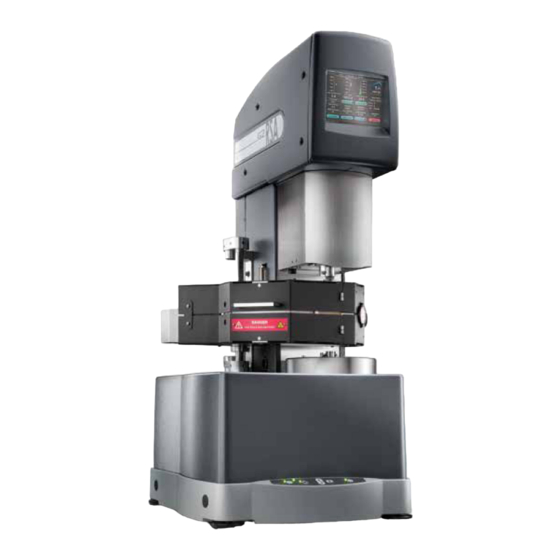
- Page 2 RSA-G2 Solids Analyzer The RSA-G2 is the most advanced platform for mechanical analysis of solids. The separate motor and transducer technology of the RSA-G2 ensures the purest mechanical data through independent control of deformation and measurement of stress. It is capable of performing the most accurate DMA measurements as well as many additional experiments including creep and recovery, stress relaxation, stress ramps, strain rate ramps, iso...
- Page 3 The Benefits of Rheology The RSA-G2 can be used for the widest range of traditional and advanced mechanical measurements and applications including: Solid and soft solid materials encounter a range of mechanical deformations (stresses and strains) over a wide variety of environmental conditions in practical daily use. This...
- Page 4 STRESS. Flow is a continuous relative change in shape per unit time, or STRAIN RATE, under influence of external STRESS. The RSA-G2 is in fact a linear rheometer, or a precision instrument. which contains a specimen of the material of interest in a geometric configuration, controls the environment around it, and applies and measures wide ranges of STRESS, STRAIN, and STRAIN RATE.
- Page 5 RSA-G2 Design Advantage At the heart of the RSA-G2 dual-head solids analyzer is the high-performance drive motor and unique transducer. The sample is deformed from the bottom by a direct-drive DC-Servo motor featuring all new electronic DSP control. The force generated in the sample is measured at the top by the patented Force Rebalance Transducer (FRT) .
- Page 6 Motor Transducer Lower Geometry Mount Temperature Sensor Rare Earth Magnet Transducer Motor Air Bearings Air Bearings Drive Motor Upper Geometry Mount Technology...
- Page 7 Linear Optical Encoder RSA-G2 Design Advantage Lead Screw The RSA-G2 transducer is mounted to the instrument frame by a linear slide and stepper motor allowing for independent vertical positioning. Transducer motion is via a precision ground lead screw attached to a...
- Page 8 High-Speed Electronics and Data Processing The RSA-G2 is equipped with new high-speed electronics with digital signal processing for transducer measurements and motor control. While many manufacturers cut costs by combining the test station and electronics into a single box, the separate electronics approach of TA Instruments RSA-G2 isolates the precision measurements from heat and vibration.
- Page 9 Forced Convection Oven with tension clamp Technology...
- Page 10 RSA-G2 SOLIDS ANALYZER Forced Convection Oven (FCO) The Forced Convection Oven is designed optimize temperature response time, The FCO is the premier temperature device for mechanical uniformity and stability. Gas is passed analysis of solids, featuring the fastest temperature response, over two resistive gun heaters and into extreme oxygen exclusion and unrivaled thermal uniformity.
- Page 11 RSA-G2 Clamping Systems The RSA-G2 features a variety of sample clamps that provide multiple modes of deformation to accommodate a wide range of sample stiffness. The RSA-G2 can easily characterize films, fibers, soft foams, pressure sensitive adhesives (PSA) , thermoplastic or thermoset bar samples, high modulus composites, metals, and even medium to high viscosity polymer melts in shear sandwich.
- Page 12 Dual and Single Shear Sandwich Compression Contact Lens Fixture Cantilever In Shear Sandwich, two equal-size pieces In this mode, the sample is placed The Contact Lens Fixture was designed of a material are ·sandwiched" between between upper and lower round plates testing the dynamic mechanical Cantilever modes are also known as two ends and a central plate.
- Page 13 IMMERSION TESTING CLAMPING SYSTEMS...
- Page 14 The RSA-G2 lmmersion System was designed for mechanical testing of solid materials while immersed in a liquid. The temperature of the fluid environment is measured by a platinum resistance thermometer, PRT. immersed in the liquid, which bypasses the standard control loop of the forced convection oven.
- Page 15 DETA DIELECTRIC THERMAL ANALYSIS ACCESSORY, DETA...
- Page 16 DETA Experiments The RSA-G2 DETA accessory can easily be programmed to run a variety of standard experiments through TRIOS Software. Experiments include dielectric frequency sweeps at isothermal temperature, isothermal time sweep tests at one or more dielectric frequencies, temperature ramp tests at one or more dielectric frequencies, and temperature step and hold profiles with single or multiple dielectric frequencies.
- Page 17 DYN AMIC MECHAN ICAL AN ALYSIS TESTING MODES & APPLICATIONS Dynamic Mechanical Analysis, DMA DMA is the most common test type for measuring viscoelastic properties of materials. Both elastic and viscous characteristics of the material can be studied by imposing a sinusoidal strain (or stress) and measuring the resultant sinusoidal stress (or strain) along with the phase difference between the two sinusoidal waves (input and output) .
- Page 18 At about 0.1 % strain the modulus begins to decrease in magnitude showing the end of the LVR. Outside the LVR the output stress response to the input strain is no longer sinusoidal. Non-linear effects show up as higher odd harmonics which the RSA-G2 is able to collect. The figure shows the intensity ratio of the third to first harmonics at each strain value.
- Page 19 Note the data start in the glassy region and are measured into the (rate) of deformation. As the frequency increases, the molecular relaxations can melt demonstrating the advantage of the RSA-G2 technology. Multiple parameters only occur at higher temperatures and, as a consequence, the Tg will shift to a can be used to determine transitions including E' onset point or peaks in the E"...
- Page 20 Frequency sweeps are typically run over a limited range of 0.1 to 100 Hz as shown below on the right for Time a pressure sensitive adhesive at 70°C using the RSA-G2 shear sandwich clamp. At this temperature and frequency range, the sample is in the terminal and plateau regions.
- Page 21 DYN AMIC MECHAN ICAL AN ALYSIS TESTING MODES & APPLICATIONS Temperature/Frequency Sweep on PSA Temperature Sweeps In this test, a step and hold temperature profile is applied. At each temperature step. the sample is held at temperature for a defined amount of time to ensure temperature uniformity in the material.
- Page 22 Time Sweep In this test. the temperature, strain, and frequency are all held constant while the viscoelastic properties are measured as a function of time. Time sweep provides important information on time-dependent structural changes such as a curing reaction or fatigue studies. The right figure shows an example of a two-part epoxy cured on a supporting fiberglass braid using a dual cantilever clamp.
- Page 23 DYN AMIC MECHAN ICAL AN ALYSIS TESTING MODES & APPLICATIONS Step Tests: Creep and Stress Relaxation Step Tests, including Stress Relaxation and Creep Recovery, are so-named because the sample deformation or stress is applied in a step fashion. Both are highly sensitive tests for measuring viscoelastic properties of materials.
- Page 24 Creep and Recovery on Soft Foam Stress Relaxation on PDMS 10 6 2000 10 5 ,..0... 1500 10 4 ,..oJ< 10 3 1000 ,.."'0 :;::: : 10 2 a> Temperature: • C!::: Temperature: 25·...
- Page 25 DYN AMIC MECHAN ICAL AN ALYSIS TESTING MODES & APPLICATIONS Iso-strain and Iso-stress Tests In this mode, the strain or stress is held at a constant value and a linear heating rate is applied. These tests are valuable for assessing mechanical behavior under conditions of fixed load (stress) or fixed deformation (strain).
- Page 26 The linear slide and stepper motor for independent vertical positioning of the instrument's Linear rate transducer enable the RSA-G2 to conduct additional axial tests for the ultimate testing flexibility. A sample can be deformed under a constant linear strain rate, Hencky strain rate, force, or stress for generating more traditional stress-strain curves.
- Page 27 ACCESSORIES RSA-G2 Air Chiller Systems (ACS-2 and ACS-3) The new Air Chiller Systems are unique gas flow cooling systems that enable temperature control of the Forced Convection Oven without the use of liquid nitrogen. Equipped with mUlti-stage cascading compressors, the ACS-2 and ACS-3 permit operation of the FCO at temperatures as low as -55°C and -1 00 °C,...
- Page 28 SPECIFICATION S RSA-G2 RSA-G2 SPECIFICATIONS Minimum Force 0.0005 N Maximum Force 35 N Force Resolution 0.00001 N Dynamic Displacement Range ±0.00005 to ± 1.5 mm Displacement Resolution 1 Nanometer 101 2 P Modulus Range 103 to 3 Modulus Precision ± 1% Tan I) Sensitivity 0.0001...
- Page 29 © 2019 TA Instruments. All rights reserved. L50027.001...
- Page 30 Verso Filler Page...
- Page 31 RSA-G2 Dynamic Mechanical Analyzer getting Started guide Issued July 2022 Revision D...
- Page 32 TA Instruments may have patents, patent applications, trademarks, copyrights, or other intellectual prop- erty covering subject matter in this document. Except as expressly provided in written license agreement from TA Instruments, the furnishing of this document does not give you any license to these patents, trademarks, copyrights, or other intellectual property.
-
Page 33: Introduction
Introduction Important: TA Instruments Manual Supplement Please click the TA Manual Supplement link to access the following important information supplemental to this Getting Started Guide: • TA Instruments Trademarks • TA Instruments Patents • Other Trademarks • TA Instruments End-User License Agreement •... -
Page 34: Notes, Cautions, And Warnings
EN 61010-2-010:2003 Particular requirements for laboratory equipment for the heating of materials + Amendments. For United States UL61010-1:2004 Electrical Equipment for Laboratory Use; Part 1: General Requirements. UL61010A-2-010:2002 Particular requirements for laboratory equipment for the heating of materials + Amendments. RSA-G2 Getting Started Guide Page 4... -
Page 35: Electromagnetic Compatibility Standards
This device complies with Part 15 of the FCC rules. Operation is subject to the following two conditions: (1) This device may not cause harmful interference, and (2) this device must accept any interference received, including interference that may cause undesired operation. RSA-G2 Getting Started Guide Page 5... -
Page 36: Safety
MISE EN GARDE: Lisez les instructions d'installation, d'utilisation et de maintenance fournies avec votre déshydrateur d'air. L'utilisation et la maintenance inappropriées du déshydrateur d'air entraî- nent d'immenses dégâts sur l'instrument. Instrument Symbols The following label is displayed on the RSA-G2 Dynamic Mechanical Analyzer (DMA) for your protection: Symbol Explanation This symbol indicates that you should read this Getting Started Guide in its entirety. - Page 37 échantillons. Please heed the warning labels and take the necessary precautions when dealing with those parts of the instrument. The RSA-G2 Getting Started Guide contains cautions and warnings that must be followed for your own safety. RSA-G2 Getting Started Guide...
-
Page 38: Electrical Safety
You must unplug the instrument before doing any maintenance or repair work; voltages as high as 120/240 VAC are present in the common cabinet. DANGER: There are no customer-replaceable fuses in the RSA-G2. High voltages are present in this instrument. If you are not trained in electrical procedures, do not remove the cabinet covers unless specifically instructed to do so in the manual. -
Page 39: Mechanical Safety
DANGER: Keep your hands clear of the motor while it is running. If you need to touch it, turn OFF the motor first. DANGER: Éloignez vos mains du moteur lorsqu'il tourne. Si vous devez le toucher, arrêtez d'abord le moteur. RSA-G2 Getting Started Guide Page 9... -
Page 40: Table Of Contents
Important: TA Instruments Manual Supplement ........ - Page 41 Moving the RSA-G2 Without a Cart ........
- Page 42 Replacement Parts ............. 68 RSA-G2 Getting Started Guide...
-
Page 43: Chapter 1: Introducing The Rsa-G2
The RSA-G2 works in conjunction with a controller, TA Instruments TRIOS software, and a Forced Con- vection Oven (FCO) to make up a rheological system. Note that the FCO is the only environmental system that can be used with the RSA-G2. -
Page 44: Rsa-G2 Test Station
RSA-G2 Test Station An RSA-G2 test station, shown in the figure below, consists of several components. The primary compo- nents are the linear motor, stage, linear transducer, keypad, touch screen display, an environmental control option, and various geometries needed for experiments. - Page 45 50°C. Then the power to the instrument shuts off. The light beside the button indicates the status. To put the instrument immediately into standby mode, press and hold this button for at least 10 seconds. RSA-G2 Getting Started Guide Page 15...
-
Page 46: Rsa-G2 Touch Screen
RSA-G2 Touch Screen The RSA-G2 has an integrated touch screen display for local operator control. Interactive functions such as gap zeroing, sample loading, and setting temperature can be performed at the instrument. The functions shown on the screen change depending upon the menu being used. This section briefly describes the interactive functions shown on the touch screen displays. -
Page 47: The Rsa-G2 Status Touch Screen
The RSA-G2 Status Touch Screen The Status tab (shown in the figure below) displays the instrument status regarding air pressure, tempera- ture sensors, system status, and network communication status. It also provides easy access to system information and diagnostics that may be used to troubleshoot your instrument. -
Page 48: The Rsa-G2 Settings Touch Screen
The RSA-G2 Settings Touch Screen The Settings tab is used to identify your RSA-G2 instrument, its location, and network (IP) address infor- mation. In addition, you can adjust FCO camera focus and light and calibrate the touch screen. Figure 6 RSA-G2 Settings touch screen. -
Page 49: Linear Air Bearing Motor
The linear air bearing motor, also referred to as the actuator, deforms the sample by applying an axial strain to the sample. The motor combined with the step motor can be operated in dynamic (sinusoidal) mode or step strain and creep-recovery tests. Figure 8 RSA-G2 linear air bearing motor. RSA-G2 Getting Started Guide Page 19... -
Page 50: Bearing Lock
Modular Power Supplies The RSA-G2 uses a separate box that houses the instrument power supplies, controller, and a self- diagnostic display. These stackable units are designed to sit on the floor, under your lab bench, leaving more room on the top of the bench for other uses. -
Page 51: Environmental Control Unit
Environmental Control Unit The FCO is the only environmental system available for use with the RSA-G2. There are two optional subambient controllers for use with the FCO: LN2 Controller and Gas Chiller. Refer to the following sections for basic information regarding each specific environmental option. For more details, refer to the online help available in the TRIOS software. - Page 52 CAUTION: Make sure the purge air is flowing when the oven is on. Failure to do so could cause damage to components inside the oven. The purge line connects to the back of the RSA-G2, to the port labeled OVEN PURGE.
- Page 53 +0.05°C Stability +0.1°C Geometry compatibility Oven is compatible with all RSA-G2 and RSA III geometries (except RSA III immersion geometry) Optional accessories LN2 Controller, Chiller, Camera Operating past 500°C for extended periods of time can deteriorate the standard 17-4 stainless steel geometries.
-
Page 54: Oven Temperature Control
• Lower air PRT (used for fast-response temperature control) Using the default system settings, the RSA-G2 reports and controls the measured temperatures using the mid-oven air PRT temperature. Measured oven temperatures from all PRTs are compared to the set point temperature in the FCO control- ler, and heater power is changed to minimize the difference between the set point and measured tempera- tures. -
Page 55: Subambient Controllers (Optional)
150°C. The LN2 Con- – troller is connected between an external liquid nitrogen source and the RSA-G2 test station. Controlled by the oven supply enclosure through the software, the LN2 Controller consists of a Dewar flask, a solenoid valve to control liquid nitrogen flow into the Dewar, and hardware to control the boiling of the liquid nitro- gen to produce cold nitrogen gas within the flask. -
Page 56: Acs-3 And Chiller Panel
TA. Supported instruments and environmental systems include the DMA Q800 with standard furnace (-100°C), Discovery Hybrid Rheometer models with Environmental Test Chamber (-85°C), and ARES-G2/ RSA-G2 with Forced Convection Oven (-100°C). The ACS-3 features low-noise durable compressors (approx. 55 dB), small footprint, uninterrupted operation, CFC- free, and for specified temperature ranges, eliminates the recurring cost and safety concerns associated with handling and use of liquid nitrogen. - Page 57 134 kg (295 lbs) Dimensions of Chiller Panel Height: 86.4 cm (34 in) Width: 48.3 cm (19 in) Depth:38.1 cm (15 in) Weight of Chiller Panel 18.2 kg (40 lbs) Lowest Temperature ARES-G2/ RSA-G2 FCO: -100°C RSA-G2 Getting Started Guide Page 27...
-
Page 58: Rsa-G2 Accessories
The FCO Camera viewer is an ideal tool for data validation. FCO mounted on right side Camera of RSA-G2 enclosure Figure 15 Camera accessory installed on FCO. RSA-G2 Getting Started Guide Page 28... -
Page 59: Rsa-G2 Geometries
Additionally, factors such as anisotropy and differences in strain dependence may yield inconsistent results for different geometries. Available Geometries The following is a list of the geometries that can be used with the RSA-G2. Details for each geometry can be found in TRIOS software Online Help. •... -
Page 60: Instrument Specifications
Instrument Specifications The table found below contains the technical specifications for the RSA-G2. Table 4: RSA-G2 Technical Specifications Item/Area Specifications Test station Depth 56 cm (22 in.) Width 46 cm (18 in.) Height 104 cm (39.37 in.) Power supply enclosure Depth 48 cm (19 in.) -
Page 61: Chapter 2: Installing The Rsa-G2
Preparing the System Before shipment, the RSA-G2 DMA is inspected both electrically and mechanically so that it is ready for operation upon proper installation. Only limited instructions are given in this manual; consult the online documentation for additional information. -
Page 62: Lifting/Moving The Instrument
Lifting/Moving the Instrument The RSA-G2 is a very heavy instrument. Use three people to lift and/or carry the instrument. The instru- ment is too heavy for one person to handle safely. In order to avoid injury, particularly to the back, please follow the advice below. -
Page 63: Moving The Rsa-G2 Using A Cart (Highly Recommended)
Moving the RSA-G2 Without a Cart When moving the RSA-G2 without a cart, you must have three people to perform the following procedure: The handling points on the instrument are shown. Grasp the instrument at those points. Support top section... -
Page 64: Choosing A Location
A stable work surface. A marble table is recommended. Isolation mounts on a standard lab bench are not recommended. Near • A power outlet. An RSA-G2 with an oven requires 180 to 264 VAC/50 or 60 Hz with a 20 amp outlet. • Your TA Instruments TRIOS Instrument Control Software. •... -
Page 65: Installing The Rsa-G2
The air source going into the dryer should have a minimum pressure of 80 psi (0.55 MPa). Follow the instructions below to install the air dryer. Mount the air dryer to a wall in close proximity to the RSA-G2, allowing the lines to reach the back of the instrument. See the figure below. - Page 66 Set the purge rate adjuster knob (shown below) to the setting number 2. Figure 18 Purge rate adjuster knob. Turn on the air supply and use the pressure regulator knob to set the supply pressure to 80 to 90 psi (0.55 to 0.62 MPa). Figure 19 RSA-G2 Getting Started Guide Page 36...
-
Page 67: Connecting The Test Station Ports
Connecting the Test Station Ports The ports and connections on the rear of the RSA-G2 are used to connect various components of the sys- tem to the instrument. This section describes these ports. All instructions are based on viewing the instrument from the rear. -
Page 68: Gas Pressure Specifications
Gas Pressure Specifications Air should be supplied to the RSA-G2 at 283.2 L/min (10 scfm) at a pressure of 80 to 90 psi (0.55 to 0.6 MPa). Gas connected through the N2/GAS port should be supplied at 70 to 125 psi (0.48 to 0.86 MPa) with a flow rate of 100 L/min. - Page 69 Upper Set of Signal Connections Figure 21 displays the upper set of signal connections on the back of the RSA-G2. Figure 21 RSA-G2 upper signal panel. The table below contains information regarding the upper set of signal panel connectors. Table 5:...
- Page 70 Lower Signal Panel Connections The lower signal panel labels (shown below) are common between the ARES-G2 and RSA-G2. For the connections with two labels, the first label is applicable to the ARES-G2 and the second label is applicable to the RSA-G2.
-
Page 71: Connecting Cables And Lines
Ne créez pas de risques de déclenchement en posant des câbles sur les voies d'accès. To connect the cables and gas lines, you will need access to the RSA-G2 rear panel. All directional descriptions are written on the assumption that you are facing the back of the instrument. -
Page 72: Test Station (Lower) Power Controller
To connect the power supply, follow these steps: Using the grip holds to move the test station power supply, place it on the floor close to the RSA-G2. Make sure you have access to the rear of the power supply and the RSA-G2. See the figure below. (The connections are already made in the figure.) -
Page 73: Fco Controller Power Supply
Make sure you have access to the rear of the power supply and the RSA-G2. See the figure below. Obtain the loose end of one of the accessory cables that has already been connected to the lower power... - Page 74 Connect the opposite end of the transfer line to the FCO LN2 supply connection. Connect the power cable from the LN2 Controller to the connector on the right side, above the communications port. Figure 25 FCO left- and right-hand configurations. RSA-G2 Getting Started Guide Page 44...
-
Page 75: Setting Up System Communication
This section also covers how to connect the system to a LAN. Figure 26 Router. On the RSA-G2 touch screen display, press the Display Settings tab and ensure that the software knob is set for DHCP. Using keyboard icons, enter the Machine ID and Location. -
Page 76: Connecting The Computer To Lan
11 Double-click on the TA Explorer icon on your controller desktop. 12 The RSA-G2 is recognized based on the Instrument ID. 13 Click on the instrument icon to establish communication between TRIOS software and the RSA-G2. Connecting the Computer to LAN If you wish to also connect the computer to a LAN, you will need to have already installed a network interface card. -
Page 77: Connecting The Test Station Power Cable
Consultez l'étiquette au dos de l'appareil pour vérifier la tension. Once all cables and lines have been connected to the modular power supplies and the RSA-G2 test station, you can connect the power cable. -
Page 78: Leveling The Rsa-G2
Leveling the RSA-G2 The RSA-G2 is leveled using the feet, or levelers (shown below), located on each corner. Note that the right-rear leveler is fixed in position; do not attempt to adjust this leveler. Clockwise rotation of the leveler extends it, raising the instrument at its location. - Page 79 Front-to-back adjustment: If necessary, extend both front levelers until they just touch the table top. Front levelers Figure 33 RSA-G2 front levelers. RSA-G2 Getting Started Guide Page 49...
- Page 80 NOTE: By extending both levelers in equal amounts, the left-to-right leveling that was performed in step 4 will not be disturbed. Check both the left-to-right and front-to-back leveling. Repeat step 4 through step 6, if necessary. RSA-G2 Getting Started Guide Page 50...
-
Page 81: Starting The Rsa-G2
NOTE: Ensure that the router is on first before powering on the RSA-G2; this is so an IP address can be generated for the RSA-G2. -
Page 82: Shutting Down The Rsa-G2
Shutting Down the RSA-G2 To shut down the RSA-G2, simply press and release the standby button on the front panel. This will safely power down the instrument as soon as the oven comes down to a safe operating temperature. At that point, the power shuts down and the power light turns red, indicating that the instrument is now in the standby state. -
Page 83: Chapter 3: Use, Maintenance, & Diagnostics
Use, Maintenance, & Diagnostics Using the RSA-G2 All of your RSA-G2 experiments will have the following general outline. In some cases, not all of these steps are performed. The majority of these steps are performed using the TRIOS Instrument Control Soft- ware. -
Page 84: Before You Begin
Before You Begin Before you set up an experiment, ensure that the RSA-G2, the environmental unit, and TRIOS software are installed properly. Make sure you have: • Made all necessary cable connections from the RSA-G2 to the computer and to the modular power supplies. -
Page 85: Geometry Mass
Geometry Mass Geometry mass (weight) is an important parameter that enables the RSA-G2 to account for the effects of test geometry inertia at higher frequencies. The mass of the geometries are entered when configuring a geometry in TRIOS software. Some of the geometries’ mass are listed in Table . -
Page 86: Phase Angle Check
Phase Angle Check To check the phase angle using the RSA-G2, perform a Phase Angle and Modulus Check in TRIOS soft- ware (refer to TRIOS Help for additional information). The phase angle correction compensates for possible phase shifts that may be added to force and strain due to instrument electronics. -
Page 87: Selecting And Installing A Geometry
Foams: Foams are best tested in either compression using the compression (parallel plate) geometry, or shear using the shear sandwich geometry. Testing Limits and Compliance The following factors limit the sample size that can be tested on the RSA-G2: • Motor/transducer force and displacement ranges •... -
Page 88: Definition Of Compliance And Stiffness
(kg) generated by displacement of the sample during deformation, per micron of sample displacement. The RSA-G2 measures sample deformation (strain) by taking the difference between the motor and trans- ducer displacement signals. The measurement is sensitive to limits in strain resolution, as well as variations in motor, and transducer, calibration and linearity. - Page 89 55 mm refers to the maximum actual length of the sample. This maximum sample length includes clamping of the sample, plus space in the FCO cavity to allow for a minimum amount of auto-tension to occur. RSA-G2 Getting Started Guide Page 59...
-
Page 90: Basic Instructions For Geometry Installation
Basic Instructions for Geometry Installation The following instructions provide general information for installing a geometry on the RSA-G2. Refer to TRIOS online help for further information. General Guidelines Following geometry installation, be certain to: • Place the lower geometry on the motor shaft and tighten the set screws. -
Page 91: Installing The Upper Geometry
While holding the geometry in place, tighten both set screws. The set screw head will move inward to hold the geometry in place. See the figure below. Set screws Notch aligned properly in slot Geometry baffle Geometry shaft Figure 36 Upper geometry installed on RSA-G2. RSA-G2 Getting Started Guide Page 61... -
Page 92: Installing The Lower Geometry
Tighten both set screws. The set screw head will move inward to hold the geometry in place. See the figure below. Geometry baffle Geometry shaft Set screws Notch aligned properly in slot Figure 37 Lower geometry installed on RSA-G2. RSA-G2 Getting Started Guide Page 62... -
Page 93: Creating A Procedure
Creating a Procedure The RSA-G2 is capable of performing oscillation and step tests. These tests are organized under the fol- lowing test types categories. (For detailed information, please consult the help available through TRIOS.) • Oscillation: In oscillation experiments, the material is subjected to a sinusoidal shear deformation. -
Page 94: Running An Experiment
Running an Experiment Once you have chosen and installed a geometry and loaded the sample into the RSA-G2, you will need to set up and run your experiment. This section provides basic instructions; for details on the steps involved, see the online help accessed through TRIOS software. -
Page 95: Maintaining The Instrument
Maintaining the Instrument This section provides some basic maintenance procedures that you may need to use for your RSA-G2 instrument. Cleaning Geometries After you have finished testing your sample, open the oven (if used), raise the upper geometry and brush or wipe off the sample. -
Page 96: Power Supply Maintenance
The only maintenance procedure that you can perform for the power supply units is to use a vacuum to remove dust and debris from the fans on the rear of the units. Call TA Instruments if any other service is required. -
Page 97: Cleaning The Instrument
Other than the routine maintenance listed in the previous section, there are no other repairs or service that you, as the customer, can perform. There are no customer-replaceable fuses in the RSA-G2. Contact TA Instruments regarding service or repairs, as well as the availability of service contracts and plans. -
Page 98: Replacement Parts
Replacement Parts Replacement parts for the RSA-G2 are listed below. Refer to the table below when ordering parts. Table 10: RSA-G2 Replacement Parts Part Number Description Replacement coalescing filter element 613.06404 Replacement particle filter element 613.06406 90-micron Nupro filter element 613.02001... - Page 99 TA Instruments Manual Supplement Supplement to Getting Started Guide Issued November 2013...
- Page 100 This page is intentionally blank. Page 2 TA Instruments Manual Supplement...
- Page 101 TA Instruments End-User License Agreement ........
-
Page 102: Ta Instruments End-User License Agreement
“as is” basis. d Miscellaneous: You may also store or install a copy of the TA Instruments software on a storage device, such as a network server, used only to install or run this software on other computers over an internal network. - Page 103 XP Embedded software, used in conjunction with the TAM Assistant software, is not included as part of the TA Instruments’ license agreement. Users of Windows XP Embed- ded software must abide by the terms and conditions as specified by Microsoft Corporation (Appendix A).
-
Page 104: Attachment A To Microsoft Oem Customer License Agreement For Embedded Systems
EULA Terms • You have acquired a device ("DEVICE") that includes software licensed by TA Instruments from an affiliate of Microsoft Corporation ("MS"). Those installed software products of MS origin, as well as associated media, printed materials, and "online" or electronic documentation ("SOFTWARE") are protected by international intellectual property laws and treaties. - Page 105 Microsoft Corporation are providing these links to third party sites to you only as a convenience, and the inclusion of any link does not imply an endorsement by MS or Microsoft Corporation of the third party site. Page 7 TA Instruments Manual Supplement...
- Page 106 EULA, except that (i) MS, Microsoft Corporation or their subsidiaries providing the Supplemental Components will be the licensor with respect to such Supplemental Components in lieu of "TA INSTRUMENTS" for the purposes of the EULA, and (ii) TO THE MAXIMUM EXTENT PERMITTED BY APPLICABLE LAW, THE SUPPLEMENTAL COM- PONENTS AND ANY (IF ANY) SUPPORT SERVICES RELATED TO THE SUPPLEMENTAL COMPONENTS ARE PROVIDED AS IS AND WITH ALL FAULTS.
-
Page 107: Attachment B To End-User License Agreement
"as is" basis. Miscellaneous: You may also store or install a copy of the TA Instruments software on a storage device, such as a network server, used only to install or run this software on other computers over an internal network. -
Page 108: Attachment C To End-User License Agreement Discovery™ Thermal Instruments 3Rd Party Licenses
Adobe Systems Distrubution License • Adobe Reader • FreeRTOS License • GNU General Public License • GNU Lesser General Public License • PostgreSQL License • PSF License Agreement • Zlib License • BSD License TA Instruments Manual Supplement Page 10... -
Page 109: Trademarks And Patents
The following references apply to the information presented in this document: TA Instruments Trademarks Q Series™ is a trademark of TA Instruments Waters—LLC, 159 Lukens Drive, New Castle, DE 19720. Integrity™ is a trademark of TA Instruments Waters—LLC, 159 Lukens Drive, New Castle, DE 19720. - Page 110 Heat Spreader for Rotary Rheometer describes proprietary technology patented by TA Instruments Waters—LLC (U.S. Patent No. 7,168,299). Rotary Rheometer Magnetic Bearing describes proprietary technology patented by TA Instruments Waters—LLC (U.S. Patent No. 7,137,290). System and Method for Enhanced Measurement of Rheological Properties describes proprietary technol- ogy patented by TA Instruments Waters—LLC (U.S.
- Page 111 Thermal Anlaysis Assembly with Distributed Resistance and Integral Flange for Mounting Various Cool- ing Devices describes proprietary technology patented by TA Instruments Waters—LLC (U.S. Patent No. 6,523,998). Differential Scanning Calorimeter describes proprietary technology patented by TA Instruments Waters— LLC (U.S. Patent No. 6,488,406).
- Page 112 For information on our latest products, contact information, and more, see our Web site at: http://www.tainstruments.com. TA Instruments—Waters LLC Corporate Headquarters 159 Lukens Drive New Castle, DE 19720 Telephone: 302.427.4000 Fax: 302.427.4001 Email: info@tainstruments.com TA Instruments Manual Supplement Page 14...
- Page 113 RSA-G2 Solids Analyzer Site Preparation Guide Page 1 Page 1 Revision G Issued May 2022...
-
Page 114: Table Of Contents
Table of Contents Table of Contents ......................... 2 Ideal Setup ............................ 3 System Components ........................4 Instrument Measurements......................5 Utility Requirements ........................6 Computer Requirements ......................7–8 Hardware ........................... 7 Software ..........................8 Accessories ........................... 9 ACS and Chiller Panel ....................9–11 Air Dryer .......................... -
Page 115: Ideal Setup
Ideal Setup IDEAL PLACEMENT AND BENCH MEASUREMENTS Select a location with adequate floor space and a rigid laboratory bench that is level and is in a vibration-free environment. For optimal performance it is recommended that the instrument be placed by itself on a separate marble table. Bench width: 2.1 m (7 ft) Bench depth: 76 cm (30 in) min. -
Page 116: System Components
System Components MAIN SYSTEM COMPONENTS Computer (Controller) Instrument Power Supply Enclosure Forced Convection Oven Enclosure E1. Liquid Nitrogen Controller & LN Tank E2. Air Cooling System Page 4 Page 4 Page 4 Revision G Issued May 2022... -
Page 117: Instrument Measurements
Instrument Measurements MAIN INSTRUMENT Height: 104 cm (39.37 in) Width: 46 cm (18 in) Depth: 56 cm (22 in) Weight: 87.5 kg (193 lbs) POWER SUPPLY ENCLOSURE Height: 34 cm (13.5 in) Width: 32 cm (12.5 in) Depth: 48 cm (19 in) FORCED CONVECTION OVEN ENCLOSURE Height: 11 cm (4.5 in) Width: 32 cm (12.5 in) -
Page 118: Utility Requirements
Separate N gas source must be 70–125 psig and able to sustain a flow rate of 3.5 scfm (100 L/min) *TA Instruments recommends purchasing the air dryer to account for the necessary dew point and air quality. Page 6 Page 6... -
Page 119: Computer Requirements
Computer Requirements HARDWARE REQUIREMENTS Description Requirement • Intel® Core™ i5 8400 or better Processor • 2.8 GHz with 9 MB L2 cache Memory ≥ 16 GB RAM DDR4 2666 SDRAM ≥ 80 GB free space Hard drive • 1.5 GB required for Full version of TRIOS •... -
Page 120: Software
Windows 10 must be 1709 or later. A second network card for corporate connection is recommended. Network TA Instruments is not responsible for resolving issues associated with connections to your corporate network. TA Instruments is not responsible for resolving hardware/software conflicts Conflicts created by the addition of third-party hardware or software to the computer. -
Page 121: Accessories
Accessories ACS-2 MEASUREMENTS Height: 88.5 cm (35 in) Width: 67 cm (26.5 in) Depth: 56 cm (22 in) Weight: 96 kg (211 lbs) WITHOUT Chiller Panel Weight: 112 kg (247 lbs) WITH Chiller Panel ACS-3 MEASUREMENTS Height: 112 cm (44 in) Width: 67 cm (26.5 in) Depth: 56 cm (22 in) Weight: 121 kg (267 lbs) WITHOUT Chiller Panel... - Page 122 Accessories FCO CHILLER PANEL MEASUREMENTS – SMC MODEL Height: 68.6 cm (27 in) Width: 54.6 cm (21.5 in) Depth: 20.3 cm (8 in) Weight: 8.2 kg (18 lbs) FCO CHILLER PANEL MEASUREMENTS – PARKER MODEL (DISCONTINUED) Height: 86.4 cm (34 in) Width: 48.3 cm (19 in) Depth: 38.1 cm (15 in) Weight: 15.8 kg (35 lbs)
- Page 123 Accessories AIR COOLING SYSTEM REQUIREMENTS Requirements • 50 Hz: 207–252 VAC (refer to the serial number plate on the rear of the unit. The ACS is line frequency specific.) • 60 Hz: 216–252 VAC (refer to the serial number plate on the rear of the unit. The ACS is line frequency specific.) •...
-
Page 124: Air Dryer
Customer must provide: • Means to connect to a 3/8” NPT male connector on the inlet hose (provided by TA Instruments) of the air dryer • Gauge to monitor the air into the air dryer • Water trap if there is excessive moisture levels that result in immediate condensation into water (installed by Customer’s maintenance personnel) -
Page 125: Liquid Nitrogen Controller
Keep the supply line short and provide adequate insulation to minimize gaseous nitrogen build-up in the supply line. Failure to do so may cause the Liquid Nitrogen Controller to malfunction frequently. Use the 3 ft. hose provided by TA Instruments for this reason. Circulator Power... -
Page 126: Site Preparation Checklist
The Customer assumes responsibility for any damage that occurs when the instrument is moved by someone other than a trained TA Instruments Service Representative. I hereby acknowledge that all utility requirements have been met per the checklist above and that they will be ready at the agreed time of installation. -
Page 127: Ta Instruments Offices
TA Instruments Offices For information on our latest products, contact information, and more, see our website at: http://www.tainstruments.com. To find your local TA Instruments office and contact information, visit http://www.tainstruments.com/contact/ta-directory/ TA Instruments – Waters LLC Corporate Headquarters 159 Lukens Drive...
Need help?
Do you have a question about the RSA-G2 and is the answer not in the manual?
Questions and answers