Table of Contents
Advertisement
SmartNode 5541 and 4141 Series
VoIP Gateway and eSBC
User Manual
Important
This is a Class A device and is intended for use in a light industrial environment. It is
not intended nor approved for use in an industrial or residential environment.
Sales Office:
+1 (301) 975-1000
Technical Support:
+1 (301) 975-1007
E-mail:
support@patton.com
WWW:
www.patton.com
Part Number: 07MDSN5541-SN4141-UM Rev. A
Revised: November 30, 2016
Advertisement
Table of Contents

Subscribe to Our Youtube Channel
Related Manuals for Patton SmartNode 5541 Series


Summary of Contents for Patton SmartNode 5541 Series
-
Page 1: User Manual
This is a Class A device and is intended for use in a light industrial environment. It is not intended nor approved for use in an industrial or residential environment. Sales Office: +1 (301) 975-1000 Technical Support: +1 (301) 975-1007 E-mail: support@patton.com WWW: www.patton.com Part Number: 07MDSN5541-SN4141-UM Rev. A Revised: November 30, 2016... - Page 2 All other trademarks presented in this document are the property of their respective owners. Copyright © 2016, Patton Electronics Company. All rights reserved. The information in this document is subject to change without notice. Patton Elec- tronics assumes no liability for errors that may appear in this document. Warranty Information The software described in this document is furnished under a license and may be used or copied only in accordance with the terms of such license.
-
Page 3: Summary Table Of Contents
........................40 Contacting Patton for Assistance Compliance Information . -
Page 4: Table Of Contents
............................13 SmartNode devices overview ..........................14 SmartNode 5541 Series eSBC .........................15 Port descriptions ............................16... - Page 5 ........................40 Introduction ................................41 Contact information..............................41 Contacting Patton Technical Services for Free Support ...................41 Warranty Service and Returned Merchandise Authorizations (RMAs)..............41 Warranty coverage ............................41...
- Page 6 SmartNode 5541 & 4141 Series User Manual Voice Routing—session router ..........................47 IP Services ................................48 Management .................................48 System ...................................48 Physical .................................48 Cabling ................................49 Introduction ................................50 Ethernet...
-
Page 7: List Of Figures
List of Figures SmartNode 5541 and 4141 ............. . . 14 Examples of SN5541 Series rear panels . -
Page 8: List Of Tables
List of Tables General conventions ..............12 Rear panel ports . -
Page 9: About This Guide
4, starting on page 33, leads you through the steps to set up a new SmartNode device and down- load a configuration Chapter 5, starting on page 40, contains information on contacting Patton technical support for assistance • • Appendix A, starting on page 43, provides compliance info for the SmartNode devices •... -
Page 10: Safety When Working With Electricity
CAUTION Safety when working with electricity The SmartNode device contains no user serviceable parts, and is not be opened by the user. The equipment shall be returned to Patton Electronics for repairs or repaired by qualified service personnel. WARNING Mains Voltage: In systems without a power switch, line voltages are present in the power supply when the power cord is connected. -
Page 11: Deutsch
SmartNode 5541 & 4141 Series User Manual Do not work on the system or connect or disconnect cables during periods of lightning activity. WARNING Deutsch Warnhinweise: Dieses Gerät ist NICHT für den Anschluss an das Telefonnetz (PSTN) bestimmt und auch NICHT dafür zugelassen. Es ist nur für den Anschluss an Endgeräte beim Kunden vorgesehen. -
Page 12: General Observations
SmartNode 5541 & 4141 Series User Manual General observations Do not stack multiple SmartNode devices directly on top of one another, and do not place items on top of the device. If you will be installing equipment above the SmartNode device, leave at least 2 inches (5 cm) of clearance between the devices. -
Page 13: General Information
Chapter 1 General information Chapter contents SmartNode devices overview ..........................14 SmartNode 5541 Series eSBC .........................15 Port descriptions ............................16 Reset button behavior ..........................16 Front panel LED definitions ........................17 SmartNode 4141 Series VoIP Gateway ......................19 Port descriptions ............................20 Reset button behavior ..........................20 Front panel LED definitions ........................21... -
Page 14: Smartnode Devices Overview
SIP TLS/SRTP included • SIP Registrar included • Section “SmartNode 5541 Series eSBC” on page 15 provides more information on the device. Section “Smart- Node 4141 Series VoIP Gateway” on page 19 describes the SmartNode 4141 Series. 1. Optional license required at additional charge... -
Page 15: Smartnode 5541 Series Esbc
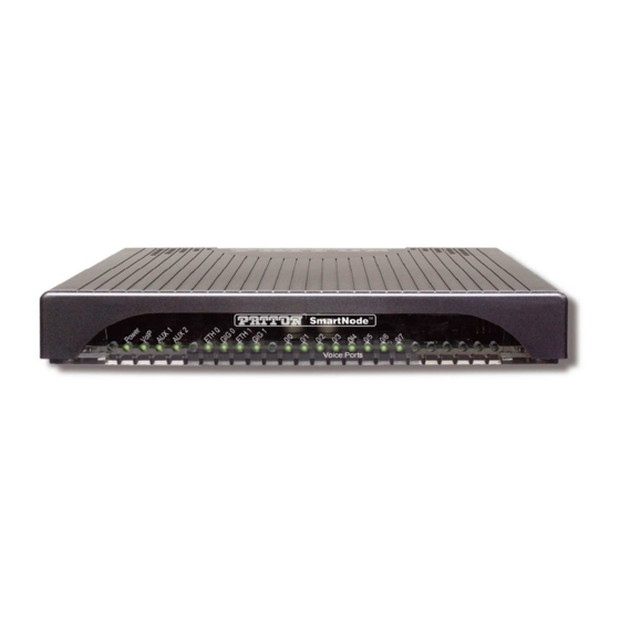
SmartNode 5541 & 4141 Series User Manual 1 • General information SmartNode 5541 Series eSBC The SmartNode 5541 eSBC Series are compact Enterprise Session Border Controllers that support 2 up to 8 voice calls (FXS–VoIP and versa) depending on the model (see... -
Page 16: Port Descriptions
EUI stands for external universal input power supply • For a complete listing of available models, refer to the SmartNode VoIP page Note https://www.patton.com/products/voip-comparison.asp Port descriptions The SmartNode 5541 Series rear panel ports are described in table Table 2. Rear panel ports Port Location Description... -
Page 17: Front Panel Led Definitions
SmartNode 5541 & 4141 Series User Manual 1 • General information 2. Pressing the Reset button will change the blink pattern. 10 seconds after the last Reset button press, an action will be performed based on the selected pattern Table 3. Power LED blink patterns Pattern Action 1 blink, pause... -
Page 18: Smartnode 5541 Led Definitions
SmartNode 5541 & 4141 Series User Manual 1 • General information If an error occurs, all LEDs will flash for more than 5 seconds before the Note device reboots. Table 4. SmartNode 5541 LED Definitions Description Power When lit, indicates power is applied. Blinks fast during bootloader phase and blinks slow during the boot process . -
Page 19: Smartnode 4141 Series Voip Gateway
On the products the following model code conventions apply: JS stands for FXS ports • EUI stands for external universal input power supply • For a complete listing of available models, refer to the SmartNode VoIP page Note at https://www.patton.com/products/voip-comparison.asp. SmartNode devices overview... -
Page 20: Port Descriptions
SmartNode 5541 & 4141 Series User Manual 1 • General information Port descriptions The SmartNode 4141 Series rear panel ports are described in table Table 5. Rear panel ports Port Location Description 10/100 Ethernet Rear panel RJ-45 connector that connects the SmartNode device to an Ethernet ETH 0/0 device (a cable or DSL modem, LAN hub or switch, for example). -
Page 21: Front Panel Led Definitions
SmartNode 5541 & 4141 Series User Manual 1 • General information Figure 5. SmartNode 4141 Series front panels Front panel LED definitions Figure 5 shows SmartNode 4141 LEDs; the LED definitions are listed in table 7 on page If an error occurs, all LEDs will flash for more than 5 seconds before the Note device reboots. -
Page 22: Smartnode 4141 Led Definitions
SmartNode 5541 & 4141 Series User Manual 1 • General information Table 7. SmartNode 4141 LED Definitions Description Power When lit, indicates power is applied. Blinks fast during bootloader phase and blinks slow during the boot process. Becomes solid when the system is up and running. VoIP •... -
Page 23: Applications Overview
Chapter 2 Applications overview Chapter contents Introduction ................................24 Application for SmartNode 5541 eSBC.........................24 Application for SmartNode 4141 VoIP Gateway....................25... -
Page 24: Introduction
2 • Applications overview Introduction Patton’s SmartNode eSBCs and VoIP Gateways deliver the features you need for advanced multi-service voice and data network applications. They combine high quality voice-over-IP with powerful quality of service rout- ing, assessment and monitoring functions to build professional, secure and reliable VoIP and data networks. -
Page 25: Application For Smartnode 4141 Voip Gateway
SmartNode 5541 & 4141 Series User Manual 2 • Applications overview Application for SmartNode 4141 VoIP Gateway The SmartNode 4141 VoIP Gateway, equipped with 1 Ethernet port, acts as a VoIP Gateway connecting POTS equipment which cannot easily be replaced by an IP-ready device (such as alarm systems, fax machines, modems, PoS terminals, etc.) into an All-IP environment (see figure The major functions of the SmartNode 4141 VoIP Gateway are:... -
Page 26: Smartnode
Chapter 3 SmartNode Installation Chapter contents Planning the Installation............................27 Site log ................................27 Network information ............................27 Network Diagram ............................27 IP related information .............................27 Software tools ..............................28 Power source ..............................28 Installing the SmartNode device ..........................28 Placing the SmartNode device .........................28 Connecting cables ............................29 Installing a grounding wire on the SmartNode device’s ground lug ............30... -
Page 27: Planning The Installation
28 to install the device. Site log Patton recommends that you maintain a site log to record all actions relevant to the system, if you do not already keep such a log. Site log entries should include information such as listed in table Table 8. -
Page 28: Software Tools
If you suspect that your AC power is not reliable, for example if room lights flicker often or there is machinery with large motors nearby, have a qualified professional test the power. Patton recommends that you include an uninterruptible power supply (UPS) in the installation to ensure that VoIP service is not impaired if the power fails. -
Page 29: Connecting Cables
SmartNode 5541 & 4141 Series User Manual 3 • SmartNode Installation Connecting cables Do not work on the system or connect or disconnect cables during periods of lightning activity. WARNING The Interconnecting cables shall be acceptable for external use and shall be rated for the proper application with respect to voltage, current, anticipated temperature, flam- WARNING mability, and mechanical serviceability. -
Page 30: Installing A Grounding Wire On The Smartnode Device's Ground Lug
SmartNode 5541 & 4141 Series User Manual 3 • SmartNode Installation Figure 8. Rear view showing location of Ethernet and FXS connectors (SmartNode 5541 shown) Installing a grounding wire on the SmartNode device’s ground lug 1. Route the grounding wire from a building ground connection to the SmartNode device. According to UL60950/IEC62368, a connection to earth ground—using the ground lug at the rear of the units (see figure... -
Page 31: Installing An Interface Cable On The Smartnode Device's Fxs Interface Ports
1. Verify that the AC power supply included with your device is compatible with local standards. If it is not, refer to Chapter 5, “Contacting Patton for Assistance” on page 40 to find out how to replace it with a com- patible power supply. -
Page 32: Power Led
SmartNode 5541 & 4141 Series User Manual 3 • SmartNode Installation 2. The power connection is made via the barrel jack on the rear panel of the SmartNode. No configuration is necessary for the power supply. Connect the female end (barrel plug) to the barrel jack on the rear of the SmartNode (see figure 2 page 15 for an SN5541 or figure 4... -
Page 33: Initial
Chapter 4 Initial Configuration Chapter contents Introduction ................................34 Connecting the SN5541 to your laptop PC......................34 Configure the desired IP address ........................34 Factory-default IP Settings ........................34 Login ................................35 Changing the WAN IP address .........................35 Connecting the SmartNode device to the network ..................36 Connecting the SN4141 to a laptop PC ........................36... -
Page 34: Configuration
SmartNode 5541 & 4141 Series User Manual 4 • Initial Configuration Introduction This chapter leads you through the basic steps to set up a new SmartNode device and to download a configuration. If you haven’t already installed the SmartNode device, refer to Chapter 3, Note "SmartNode Installation"... -
Page 35: Login
SmartNode 5541 & 4141 Series User Manual 4 • Initial Configuration DHCP server, the WAN interface uses DHCP client to automatically assign the IP address and network mask. Table 10. Factory Default IP Address and Network Mask Configuration IP Address Network Mask WAN Interface Ethernet 0 (ETH 0/0) DHCP... -
Page 36: Connecting The Smartnode Device To The Network
SmartNode 5541 & 4141 Series User Manual 4 • Initial Configuration The modified configuration is applied immediately. It is not necessary to Note reboot the device when changing any configuration parameter. 172.16.1.99(if-ip) [WAN]#copy running-config startup-config 172.16.1.99(if-ip) [WAN] The SmartNode can now be connected to your network. Connecting the SmartNode device to the network In general, the SmartNode will connect to the network via the WAN (ETH 0/0) port. -
Page 37: Connecting The Smartnode To A Laptop Pc
SmartNode 5541 & 4141 Series User Manual 4 • Initial Configuration The SmartNode device has a fixed IP and a DHCP client setup to simplify Note configuration. The Ethernet port is equipped with Auto-MDX so you can use a straight-through cable for host or hub/switch connection. There are two options for configuring the SmartNode device 1. -
Page 38: Configure The Desired Ip Address
SmartNode 5541 & 4141 Series User Manual 4 • Initial Configuration You can check the connection to the SmartNode by executing the ping command from the PC command win- dow as follows: ping 192.168.1.1 Configure the Desired IP Address Factory-default IP Settings 10. -
Page 39: Loading The Configuration (Optional)
Loading the Configuration (optional) WebWizard Community provides a collection of Wizards that help to reduce the setup time of a Patton device. Simply download the appropriate Wizard to your device, execute it locally, and you are ready to do phone calls after the SmartNode has rebooted. -
Page 40: Contacting Patton For Assistance
Chapter 5 Contacting Patton for Assistance Chapter contents Introduction ................................41 Contact information..............................41 Contacting Patton Technical Services for Free Support ...................41 Warranty Service and Returned Merchandise Authorizations (RMAs)..............41 Warranty coverage ............................41 Out-of-warranty service ..........................42 Returns for credit ............................42 Return for credit policy ..........................42... -
Page 41: Introduction
(RMA). Contact information Patton Electronics offers a wide array of free technical services. If you have questions about any of our other products we recommend you begin your search for answers by using our technical knowledge base. Here, we have gathered together many of the more commonly asked questions and compiled them into a searchable database to help you quickly solve your problems. -
Page 42: Out-Of-Warranty Service
RMA#: xxxx 7622 Rickenbacker Dr. Gaithersburg, MD 20879-4773 USA Patton will ship the equipment back to you in the same manner you ship it to us. Patton will pay the return shipping costs. Warranty Service and Returned Merchandise Authorizations (RMAs) -
Page 43: A Compliance Information
Appendix A Compliance Information Chapter contents Compliance ................................44 ................................44 Safety ................................44 Radio and TV interference ............................44 CE Declaration of Conformity ..........................44 Authorized European Representative ........................44... -
Page 44: Compliance
AC outlet (such that the computing equipment and receiver are on different branches). CE Declaration of Conformity Patton Electronics, Inc declares that this device is in compliance with the essential requirements and other pro- visions of Council Directive 1999/5/EC on the approximation of the laws of the member states relating to Radio and Telecommunication Terminal Equipment and the mutual recognition of their conformity. -
Page 45: Specifications
Appendix B Specifications Chapter contents DSP..................................46 Voice Connectivity ..............................46 Data Connectivity ..............................46 Voice Processing (signalling dependent) ........................46 Fax and modem support............................47 Voice Signalling..............................47 Voice Routing—session router ..........................47 IP Services ................................48 Management .................................48 System ...................................48 Physical .................................48... -
Page 46: Dsp
For a complete listing of available models, refer to the SmartNode VoIP page Note at https://www.patton.com/products/voip-comparison.asp. One 8-channel DSP. 2V and 4V models are restricted by software to not allow more than 2/4 calls. Upgrade- able by license to max. 8 calls, which can also be used for SIP to SIP call transcoding. -
Page 47: Fax And Modem Support
SmartNode 5541 & 4141 Series User Manual B • Specifications Configurable tones (dial, ringing, busy, etc.) Configurable transmit packet length RTP/RTCP (RFC 1889) SRTP (RFC 3711) Fax and modem support Automatic fax and modem detection Codec fallback for modem-bypass T.38 Fax-Relay (Gr. 3 Fax, 9.6 k, 14.4 K) G.711 Fax-Bypass Super G3 fax Voice Signalling... -
Page 48: Ip Services
SmartNode 5541 & 4141 Series User Manual B • Specifications IP Services IPv4 router; IPv6 basic functionalities Routing functionalities are included on SN5551 and optional on SN4151 • • • OpenVPN (License at additional charge) Programmable static routes and policy-routing ICMP redirect (RFC 792);... -
Page 49: Cabling
Appendix C Cabling Chapter contents Introduction ................................50 Ethernet ................................50 Analog FXS ................................51... -
Page 50: Introduction
SmartNode 5541 & 4141 Series User Manual C • Cabling Introduction This section provides information on the cables used to connect the SmartNode device to the existing network infrastructure and to third party products. Ethernet Ethernet devices (10/100/1000 Base-T) are connected to the SmartNode over a cable with RJ-45 plugs. All Ethernet ports on the SmartNode device are Auto-MDX. -
Page 51: Analog Fxs
SmartNode 5541 & 4141 Series User Manual C • Cabling Analog FXS The Interconnecting cables shall be acceptable for external use and shall be rated for the proper application with respect to volt- age, current, anticipated temperature, flammability, and CAUTION mechanical serviceability. -
Page 52: D Port Pin-Outs
Appendix D Port pin-outs Chapter contents Introduction ................................53 Ethernet ................................53 port................................53... -
Page 53: Introduction
SmartNode 5541 & 4141 Series User Manual D • Port pin-outs Introduction This section provides pin-out information for the ports of the SmartNode. Ethernet Table 12. 10/100 Base-T RJ-45 socket Signal Pins not listed are not used. Note Table 13. 1000Base-T RJ-45 Socket Signal TRD0+ TRD0-... -
Page 54: Rj-11 Pinout Diagram
SmartNode 5541 & 4141 Series User Manual D • Port pin-outs Figure 18. RJ-11 pinout diagram FXS port... -
Page 55: E Smartnode Device Factory Configuration
Appendix E SmartNode Device Factory Configuration Chapter contents Introduction ................................56... -
Page 56: Introduction
SmartNode 5541 & 4141 Series User Manual E • SmartNode Device Factory Configuration Introduction Factory configuration settings for the SmartNode device can be obtained with the following command through the CLI; login: admin password: <Enter> 192.168.1.1>show config:shipping-config See Chapter 4, "Initial Configuration"... -
Page 57: F End User License Agreement
Appendix F End User License Agreement Chapter contents End User License Agreement ..........................58 1. Definitions ..............................58 2. Title ................................58 3. Term ................................58 4. Grant of License ............................58 5. Warranty ..............................58 6. Termination ..............................59 7. Other Licenses ............................59... -
Page 58: End User License Agreement
Program(s), even if Patton Electronics Company has been advised of the possibility of such damages. Because some states do not allow the exclusion or limitation of liability for consequential or incidental damages, the above limitation may not apply to you. -
Page 59: Termination
The End user may terminate this agreement by returning the Designated Equipment and destroying all copies of the licensed Program(s). Patton Electronics Company may terminate this Agreement should End User violate any of the provi- sions of section, “4. Grant of License”...
Need help?
Do you have a question about the SmartNode 5541 Series and is the answer not in the manual?
Questions and answers