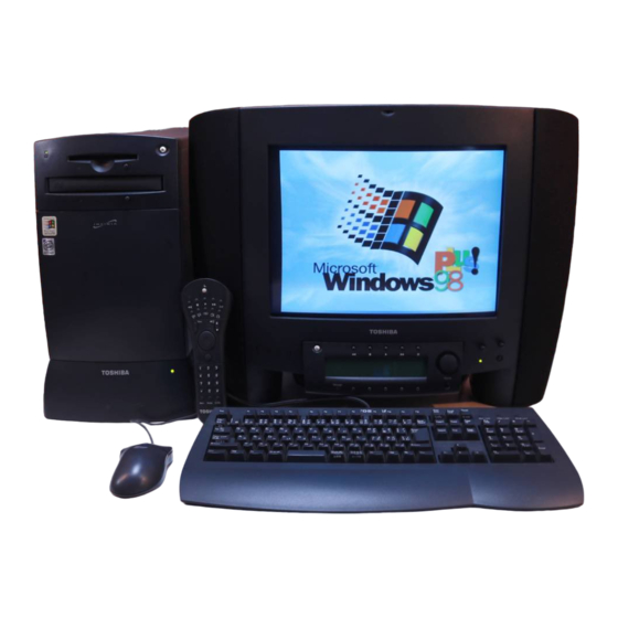
Toshiba Infinia 7130 Series Maintenance Manual
Hide thumbs
Also See for Infinia 7130 Series:
- Resource manual (56 pages) ,
- Specification sheet (4 pages)
Table of Contents
Advertisement
Quick Links
Advertisement
Chapters
Table of Contents


Need help?
Do you have a question about the Infinia 7130 Series and is the answer not in the manual?
Questions and answers