Table of Contents
Advertisement
Quick Links
Progress Solar
& Solar/Wind
Light Tower
TM
TM
Operator Manual
(SLT 700 to 1400 Series)
(SLTW 700 to 1400 Series)
Progress Solar
TM
& Solar/Wind
TM
Light Tower
Operator Manual
w. ProgressSolarSolutions.com
Parts@ProgresssSolarSolutions.com
p. 919.363.3738
1108 N New Hope Rd, Raleigh, NC 27610
1 |
P a g e
Advertisement
Chapters
Table of Contents
Troubleshooting

Subscribe to Our Youtube Channel
Summary of Contents for Progress Solar/Wind SLT 700 Series
- Page 1 Progress Solar & Solar/Wind Light Tower Operator Manual (SLT 700 to 1400 Series) (SLTW 700 to 1400 Series) Progress Solar & Solar/Wind Light Tower Operator Manual w. ProgressSolarSolutions.com Parts@ProgresssSolarSolutions.com p. 919.363.3738 1108 N New Hope Rd, Raleigh, NC 27610 P a g e...
- Page 2 Table of Contents Operator’s Manual Page # Table of contents ......................2 Introduction ........................3 Safety Alert Symbols ....................4 Safety Information ...................... 4-6 Serial & Model Number Locations ................6 Specifications & Dimensions ..................7-8 Components ......................9-13 Inspection Checklist ....................14 Operating Instructions ...................
- Page 3 information, please contact the factory or your local dealer before continued use. Make this information available to all who may use or will be working around the Progress Solar (SLT) or Progress Solar/Wind (SLT(W)) Light Towers to ensure a safe working environment and a properly maintained system.
- Page 4 Safety Information Alert symbols are located where danger is present, a warning is necessary or cautionary measures need to be taken. Be aware of these symbols and follow advised safety instructions to avoid harm to yourself, others or the unit. The following symbols identify the level of exposure to the operator of the unit.
- Page 5 FLUSH EYES WITH WATER AND SEEK MEDICAL ASSISTANCE. DO NOT CHARGE BATTERIES WITHOUT PROPER INSTRUCTION. NOTE: THE ABOVE WARNING IS BASED PRIMARILY ON FLOODED BATTERIES, ALL PROGRESS SOLAR UNITS USE AGM SEALED BATTERIES BUT THE PRECUTIONS MAY STILL BE RELEVANT IF CASE IS PIERCED.
- Page 6 MAKE SURE ALL CONNECTIONS ARE TIGHT. DO NOT OVER-TIGHTEN CONNECTION ON THE BATTERY TO DETER DAMAGE TO TERMINALS OR BATTERY CASE. DO NOT LEAVE THE BATTERY ON A TRICKLE CHARGER FOR MORE THAN 48 HOURS. BATTERIES SHOULD BE KEPT CLEAN AND FREE FROM ANY CORROSION. ...
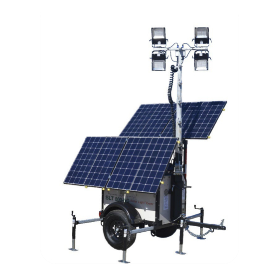
- Page 7 The high wind stabilization package includes 4 Progress Solar Tele-Struts™ to secure the solar wings and the 5 outriggers/jacks stabilize the unit during high wind.
- Page 8 Light Tower & Control Module Multi-stage light tower that can expand from ~8’ to 23’ (standard size). Wind turbine must be housed on same mast assembly and extends ~2’ above lights Photocell – Activates lights in darkness when turned on ...
- Page 9 Components Solar Array Solar Arrays consisting of Mono-Crystalline Solar Modules housed on two Solar Wings with Electric Actuators. Tele-Struts Tele-Struts - Used to stabilize solar wings during high winds, with use of Tele-tabs and pins. Included in units that have the high-wind package. P a g e...
- Page 10 Control Box Front Control Box (Top Half) Remote Meter(s) ‘TriStar’ for MPPT Charge Controllers to allow user to view performance in real time. Victron BMV – Smart Battery monitor. Displays: voltage, amperage, ampere- hours consumed, wattage, hours remaining, etc. (older units may have a red, yellow, green state of charge meter) Light Control Switch - Three-way switch.
- Page 11 Front Control Box (lower Half) Breaker(s) to engage or disengage electrical circuits (up is ON, down is OFF) Battery State-Of-Charge Meter to enable visual real time visualization of available power (not shown). Solar Wings – Use rocker switches to automatically raise and lower solar wings using actuators USB Cables to enable download...
- Page 12 Trailer & Housing Outriggers/Jack Stands - to level unit and support the raised light tower mast. Deploy outriggers/jacks for stability. Located at the front (optional), rear and tongue of the trailer to provide stability while light tower is deployed. Tongue Jack Stand- Jack stand is used to level and support the tongue and enable attachment / detachment of the light tower to a vehicle for towing.
- Page 13 Light Tower LED Light Module / Tower / and Optional Wind Turbine Solid-State LED Flood Lights – Each light can rotate 360 Degrees and tilt up or down Tower: Tower Extension Winch- This self-braking winch extends the mast to the desired height, up to ~23’ for most models Tower Rotation- Tower can rotate to approximately 180 degrees using tower pivot ring to provide optimum angle for your lights...
- Page 14 Inspection Checklist PREPARE FOR USE OF PROGRESS SOLAR™ or SOLAR/WIND™ LIGHT TOWER Never put into use or deliver any unit that has been damaged or has missing decals. Replace any safety or instructional decals that are difficult to read. Inform the end user how to safely operate the unit as stated by the operator manual.
- Page 15 Operating Instructions Transport & Towing Close solar wings completely into down position tightly against the sides of the unit before transit. Secure all latches and connectors prior to transit. Lower light tower down to its lowest position. It is optional but encouraged to turn ...
- Page 16 Setup Light Tower Operation 1. Read Operator’s Manual before starting. 2. Park the unit with the tow tongue facing east or west. This will allow the solar wings on either side to be raised to face the sun (solar south in Northern Hemisphere) and maximize solar gain as the sun rises in the east and sets in the west.
- Page 17 The Light controls and light timer are located inside the control box. This component regulates light times and prevents over discharging of the batteries The Progress Solar Light Tower provides a Light Timer to operate the lights and manage power consumption.
- Page 18 For entertainment or sporting events, you can set the Light Timers to turn on the lights • from 6pm until 11pm or for whatever times fit your purpose. If you want to start earlier than the automated timer setting, you can always manually turn the Lights on with the Timer by pushing the manual key until the red light comes on, and then push the key a second time to return it to automatic.
- Page 19 3) To review programs Press TIMER to alternate and display each setting on the LCD screen. 4) To operate, Press MANUAL to select ON, AUTO or OFF setting mode. Note a will appear under ON, AUTO or OFF to designate current operating mode and will cycle if you press MANUAL.
- Page 20 Maximum Power Point Tracking (MPPT) Controller Operation The MPPT Controllers are located inside the control box. The component is an advanced maximum power point tracking (MPPT) solar battery charger and load controller for stand- alone off-grid photovoltaic (PV) systems. This controller features a smart tracking algorithm that maximizes the energy from the solar module(s) and also provides load control to prevent overcharging or over-discharging of the batteries.
- Page 21 Deep-Cycle AC Battery Charger Operation The battery charger is located inside the main housing unit with an external electrical plug / outlet to allow the operator to provide a rapid charge to the unit’s battery bank. This method is designed as a backup or secondary way of charging the batteries.
- Page 22 Optional Inverter/charger: There is a 30amp twist lock plug located on the Drivers side of the unit, near the front (see picture). Use the provided power cord that is wrapped around the cable wrap to connected the female end to the unit and the male end to shore power.
- Page 23 Maintenance Trailer: Mend brake light quick connect wiring if wires become stripped or exposed. Keep tires at correct PSI. Replace worn tires. Rinse trailer periodically after traveling through salty conditions. Solar Wings: Keep solar modules clean by wiping them with a dry cloth, using water or glass ...
- Page 24 Charge Controller: Tighten all terminals. Check for broken, lose or charred wire connections. Clean area surrounding the controller and free any debris that may be lodged. Maintain airflow around the controller. Keep controller out of a wet environment. Make sure there are no leaks in the ...
- Page 25 MANUFACTURER’S WARRANTY Progress Solar Solutions™, LLC (PSS) warrants that all Progress Solar (SLT) & Solar/Wind Light Towers (SLTW) that are manufactured by PSS will be free from defects in material and workmanship for a period of 2 years after date of delivery to first purchaser.
- Page 26 Manufacturer Certification Label Example Manufactured By: Progress Solar Solutions LLC. 1108 N New Hope RD, Raleigh, NC 27610 Oct 2020 GVWR 1034 KG (2280 LB) GAWR 588 KG (3500 LB) TIRES ST205/75 D 14 RIMS 14X5.5 JJ COLD WEATHER INFL...
- Page 27 TROUBLESHOOTING GUIDE SLT, SLTW, SHYB MODELS Lights Q) All 4 of my lights are not working. • A) First check circuit breaker: Set in the ON position (which is UP). Breaker should be showing red which means ◦ the system is hot. •...
- Page 28 • You will want to check the continuity going from the front box going to the lights to make sure you don’t have a cut wire somewhere on the 12/4 coil cable. ◦ To do this locate the color wires in the J-Box in between the lights. Using 1 lead place it on 1 colored wire and the other lead on the same-colored wire in the control box.
- Page 29 Q) Can I charge my unit with a wall outlet or generator? • A) Yes, there is an on-board AC battery charger built into your unit. ◦ There is a receptacle located on the rear passenger side that you can plug a power supply to the battery charger.
- Page 30 Delta Volt Fuel Gauge Q) My fuel gauge shows my battery capacity in the RED for several days in a row. Is my unit charging? • A) YES, once your fuel gauge enters the RED it will not move back up the LED line till your battery voltage reach's 26 volts.
- Page 31 Wind Turbine (SLTW Models) Q) How do I know the wind turbine is producing power? • A) The wind turbine switch must be in the ON position. If there’s enough wind to rotate the turbine and produce power, a solid green led light •...
- Page 32 Gas/LPG Hybrid Generator (SHYB Models) Q) Why don’t I have any power to my generator? • A) Check to make sure the main Disconnect Switch located in the front of the unit is in the ON position. Check to make sure the light for the generator battery is ON and the led indicator is ◦...
- Page 33 If you have manually cranked generator and it’s not cranking over ▪ • Check starting battery leads make sure these leads are across the main battery bank for only 12V. The Negative lead should be on the main negative i.e., parallel connection.
- Page 34 Q) I got the generator running but I had to move the choke lever to the left to get it running. • A) If you have to close the choke lever to get the generator running, you probably have a leak in the fuel supply. •...
- Page 35 ENGLISH Manual - BMV-712 Smart Battery monitor Rev 10 - 12/2022 This manual is also available in HTML5.
-
Page 36: Table Of Contents
Manual - BMV-712 Smart Table of Contents 1. Safety precautions ........................1 1.1. General safety precautions ....................1 1.2. Battery safety warnings ..................... 1 1.3. Transport and storage ...................... 1 2. Introduction ........................... 2 2.1. The battery monitor ......................2 2.2. - Page 37 Manual - BMV-712 Smart 7. All features and settings ......................28 7.1. How to change settings ....................28 7.1.1. Accessing settings via the head unit ................28 7.1.2. Accessing settings via the VictronConnect app .............. 28 7.1.3. Saving, loading and sharing settings in VictronConnect ............ 28 7.2.
- Page 38 Manual - BMV-712 Smart 7.7.2. Reset PIN code ....................41 7.7.3. Temperature unit setting ..................41 7.7.4. Serial number ....................42 7.7.5. Disabling and re-enabling Bluetooth ................42 7.7.6. Changing PIN code ..................... 42 7.7.7. Custom name ....................42 7.7.8. Firmware ......................42 7.7.9.
-
Page 39: Safety Precautions
Manual - BMV-712 Smart 1. Safety precautions 1.1. General safety precautions Read this manual carefully. It contains important instructions that must be followed during installation, operation and maintenance. Save these instructions for future reference on operation and maintenance. 1.2. Battery safety warnings Working in the vicinity of a lead acid battery is dangerous. -
Page 40: Introduction
Manual - BMV-712 Smart 2. Introduction 2.1. The battery monitor The BMV-712 Smart is a battery monitor. It measures battery voltage and current. Based on these measurements, it calculates the battery's state of charge and the time to go. It also keeps track of historical data, such as deepest discharge, average discharge and the number of charge and discharge cycles. -
Page 41: Accessories
Manual - BMV-712 Smart 2.5. Accessories These optional parts might be needed depending on your setup: • Temperature sensor for BMV - to measure the battery temperature. • GX Device, such as a Cerbo GX - for system and/or remote monitoring. •... -
Page 42: Installation
Manual - BMV-712 Smart 3. Installation 3.1. What's in the box? BMV-712 Smart head unit together with attachment sleeve. 500A shunt. Two 1.5m (59") red cables with a 1A fuse. 10m (33ft) RJ12 UTP cable. Square face plate together with an attachment flange. -
Page 43: Mounting The Head Unit
Manual - BMV-712 Smart For the exact location of the mounting holes see the dimension drawing [56] in the appendix of this manual. Top view shunt indicating mounting holes and side view shunt indicating the mounting method. 3.3. Mounting the head unit The head unit can be mounted in a variety of ways: A. - Page 44 Manual - BMV-712 Smart Mounting method B. Mounting method C. For the full wall mounting instructions, see the wall mounting installation manuals on the Wall mount enclosure for BMV or MPPT Control Wall mount enclosure for BMV and Color Control GX product pages.
-
Page 45: Connections Overview
Manual - BMV-712 Smart 3.4. Connections overview Name Terminal type Display Setup button Down button Up button Select button RJ12 connector RJ2 terminal Buzzer Programmable relay connector Push connector VE.Direct connector VE.Direct terminal Negative battery connection M10 bolt Positive battery connection M10 ring terminal Auxilary connection Push connector... -
Page 46: Auxiliary Electrical Connections
Manual - BMV-712 Smart Loads & Chargers Battery bank Basic battery monitor installation. 3.6. Auxiliary electrical connections In addition to the comprehensive monitoring of the main battery bank, a second parameter can be monitored. This can be one of the following: •... -
Page 47: Auxiliary Connection For Temperature Monitoring
Manual - BMV-712 Smart 1. Connect the ferrule pin of the second red cable with fuse to the shunt by pushing the pin into to the +B2 terminal. 2. Connect the M10 lug of the second red cable with fuse to the positive terminal of the midpoint. For more information on midpoint monitoring and for additional diagrams on midpoint battery bank wiring see the Midpoint voltage monitoring [46]... -
Page 48: Use Of Alternative Shunts
Manual - BMV-712 Smart A usage example of the relay is to start a generator when the battery state of charge has dropped too low, and then to stop the generator when the batteries have been recharged. By default, the relay is set to energise when the battery state of charge falls below 50% and to de-energise when the battery state of charge has risen to 90%. -
Page 49: Wiring For Use As Dc Meter
Manual - BMV-712 Smart The battery monitor is connected to a Cerbo GX and a GX Touch screen. 3.10. Wiring for use as DC meter When using the battery monitor as a DC meter, wire it to the device or circuit that needs to be monitored. Note that the battery monitor also needs to be configured as a DC monitor using the VictronConnect app before it will operate as a DC monitor. -
Page 50: Configuration
Manual - BMV-712 Smart 4. Configuration Once the electrical connections have been made, and the battery monitor has been powered up, it needs to be configured to be suitable for the system it is used in. This can be done with the buttons on the battery monitor head unit or even easier via the VictronConnect app. This chapter describes how to configure the battery monitor by making the basic settings. -
Page 51: How To Change Settings
Manual - BMV-712 Smart Measured voltage Assumed nominal voltage > 36V Note that the battery monitor is unable to detect a 32V nominal battery voltage. If the battery monitor is used with a 32V battery bank, the charged voltage must be set manually using the Charged voltage [29] setting. -
Page 52: The Victronconnect App
Manual - BMV-712 Smart Press SETUP to return to the setting menu. Go to the next setting using the + or - buttons. After all settings have been made, press SETUP to return from the settings menu to normal mode. 4.3.2. -
Page 53: Update Firmware
Manual - BMV-712 Smart 4.4. Update firmware On a new install, it is recommended to update the firmware of the battery monitor. If there is a newer firmware version available, the VictronConnect app will notify you of this as soon as a connection with the battery monitor is made. Note that the firmware can only be updated via the VictronConnect app. -
Page 54: Set State Of Charge
Manual - BMV-712 Smart 4.5.3. Set state of charge In the VictronConnect app, see: Settings > Battery > Battery start synchronized. Via the head unit, see: Setup menu > Setting 70 - Start synchronised. When set to ON, the battery monitor will consider itself synchronized when powered up, resulting in a state of charge of 100%. If set to OFF, the battery monitor will consider itself un-synchronized when powered up, resulting in a state of charge that is unknown until the first actual synchronization. -
Page 55: Configure For Use As Dc Meter
Manual - BMV-712 Smart Important warning Lithium batteries are expensive and can be irreparably damaged due to very deep discharge or overcharge. Damage due to deep discharge can occur if small loads slowly discharge the battery when the system is not in use. -
Page 56: Operation
Manual - BMV-712 Smart 5. Operation 5.1. How does the battery monitor work? The main function of the battery monitor is to follow and indicate the state of charge of a battery, to be able to know how much charge the battery contains and to prevent an unexpected total discharge. The battery monitor continuously measures the current flow in and out of the battery. -
Page 57: Using The Head Unit Menus
Manual - BMV-712 Smart as it is a momentary readout and should be used as a guideline only. We recommend the use of the state of charge readout for accurate battery monitoring. If the “Time remaining” indicates three dashes: “---” this means that the battery monitor is in an unsynchronised state. This occurs when the battery monitor has just been installed or after it has been left unpowered and is powered up again. -
Page 58: History
Manual - BMV-712 Smart • Voltage (V). • Current (A). • Power (W). • Consumed Amp Hours (Ah). • State of charge (%). • Temperature (°C). VictronConnect app battery monitor trends. 5.5. History The battery monitor stores historic events. These can be used at a later date to evaluate usage patterns and battery health. The history data is stored in a non-volatile memory and will not be lost when the power supply to the battery monitor has been interrupted or when the battery monitor has been reset to its defaults. -
Page 59: Accessing Historical Data Via The Head Unit
Manual - BMV-712 Smart The VictronConnect app battery monitor history screen. 5.5.2. Accessing historical data via the head unit To view the battery monitor history menu press SELECT when in normal mode: • Press + or – to browse the various parameters. •... -
Page 60: History Data
Manual - BMV-712 Smart Display Discription Lowest AUX voltage Highest AUX voltage Discharged energy Charged energy 5.5.3. History data Discharge information in Ah • Deepest discharge: The battery monitor remembers the deepest discharge and each time the battery is discharged deeper the old value will be overwritten. -
Page 61: Synchronising The Battery Monitor
Manual - BMV-712 Smart The alarm will activate when the value reaches a set threshold and will deactivate when the value clears this threshold. The thresholds are configurable. For more information, see the Alarm settings [34] chapter. The alarm will be displayed on the head unit, a buzzer will sound, the display backlight will flash, and the alarm icon will be visible on the display. -
Page 62: Operation As A Dc Meter
Manual - BMV-712 Smart A manual synchronisation can also be needed when the battery has not been fully charged, or if the battery monitor has not detected that the battery has been fully charged because the charged voltage, current or time has been set incorrectly. In this case, review the settings and make sure the battery regularly receives a full charge. -
Page 63: Interfacing
Manual - BMV-712 Smart 6. Interfacing The battery monitor can be connected to other equipment, this chapter describes how this can be done. 6.1. VictronConnect app via USB The VictronConnect app can not only connect via Bluetooth but it can also connect via USB. A USB connection is essential when connecting to the Windows version of the VictronConnect app and is optional when the MacOS or Android version is used. -
Page 64: Connecting To Ve.smart Networking
Manual - BMV-712 Smart Example of a battery monitor connecting to a GX device. 6.3. Connecting to VE.Smart networking VE.Smart networking is a wireless network that allows a number of Victron products to exchange information via Bluetooth. The battery monitor can share the following information with the network: •... -
Page 65: Custom Integration
Manual - BMV-712 Smart Example of a system containing a battery monitor with a temperature sensor and a solar charger, both using the VE.Smart networking. 6.4. Custom integration Please note that this is an advanced feature and requires programming knowledge. The VE.Direct communications port can be used to read data and change settings. -
Page 66: All Features And Settings
Manual - BMV-712 Smart 7. All features and settings This chapter explains all battery monitor settings. In addition to this we also have a video available explaining these settings and how the interact with each other to achieve accurate battery monitoring for both lead acid and lithium batteries. Link to the video: https://www.youtube.com/embed/mEN15Z_S4kE 7.1. -
Page 67: Charged Voltage
Manual - BMV-712 Smart 7.2.2. Charged voltage The battery voltage must be above this voltage level to consider the battery as fully charged. As soon as the battery monitor detects that the voltage of the battery has reached this “charged voltage” parameter and the current has dropped below the “tail current [29]”... -
Page 68: Charge Efficiency Factor
Manual - BMV-712 Smart Setting Default Range Step size Peukert exponent (setting 05) 1.25 1.00 - 1.50 0.01 7.2.7. Charge efficiency factor The “Charge Efficiency Factor” compensates for the capacity (Ah) losses during charging. A setting of 100% means that there are no losses. -
Page 69: State Of Charge
Manual - BMV-712 Smart Setting Default Modes Start synchronized (setting 70) ON/OFF 7.2.11. State of charge With this setting, you can manually set the state of charge value. This setting is only active after the battery monitor has, at least once, been synchronised. -
Page 70: Invert Relay
Manual - BMV-712 Smart Setting Default mode Modes Description DFLT The relay settings 16 up to 31 can be used to control the relay. Default mode. The relay will close when the state of charge falls below setting 16 (discharge floor) or when the battery voltage falls below setting 18 (low voltage relay). -
Page 71: Low Voltage Relay
Manual - BMV-712 Smart When the state of charge percentage has risen above the "clear relay" value, the relay will open (after a delay, depending on the Relay minimum closed time [32] and/or the Relay off delay [32] settings). The "clear relay" value needs to be greater than the "set relay" value. Setting Default Range... -
Page 72: Low Temperature Relay
Manual - BMV-712 Smart The "clear relay" value needs to be greater than the "set relay" value. Setting Default Range Step size Set relay value (setting 24) 0 - 95V 0.1V Clear relay value (setting 25) 0 - 95V 0.1V 7.3.11. -
Page 73: Low Voltage Alarm
Manual - BMV-712 Smart Setting Default Range Steps Set alarm value (setting 33) 0 - 100% Clear alarm value (setting 34) 0 - 100% 7.4.3. Low voltage alarm When enabled, the alarm will activate when the battery voltage falls below the set value for more than 10 seconds. The alarm will deactivate when the battery voltage rises above the clear value. -
Page 74: High Starter Voltage Alarm
Manual - BMV-712 Smart 7.4.6. High starter voltage alarm This setting is only available if the Aux input has been set to “Starter battery”, see chapter Aux input [40]. When enabled, the alarm will activate when the starter battery voltage rises above the set value for more than 10 seconds and the alarm will deactivate when the starter battery voltage drops below the clear value. -
Page 75: Scroll Speed
Manual - BMV-712 Smart Setting Default Modes Backlight always on (setting 50) 7.5.3. Scroll speed The scroll speed of the display. This setting ranges from 1 (very slow) to 5 (very fast). Setting Default Range Step size Scroll speed (setting 51) 1 - 5 7.5.4. -
Page 76: Starter Voltage Display
Manual - BMV-712 Smart 7.5.10. Starter voltage display Must be set to ON to display the auxiliary voltage in the monitoring menu. Setting Default Modes Starter voltage display (setting 58) 7.5.11. Temperature display Must be set to ON to display the battery temperature in the monitoring menu. Setting Default Modes... -
Page 77: Miscellaneous Settings
Manual - BMV-712 Smart 7.6. Miscellaneous settings 7.6.1. Software version Setting 61 This is a read-only setting. it displays the firmware version of the battery monitor. The software version as displayed on the head unit is the same as the firmware version as displayed in the VictronConnect app product settings. -
Page 78: Shunt Current
Manual - BMV-712 Smart 7.6.5. Shunt current When a shunt other than the one supplied with the battery monitor is used, use this setting to set the rated current of the shunt. Setting Default Range Step size Shunt current (setting 65) 500A 1 - 9999A 7.6.6. -
Page 79: Bluetooth Mode
Manual - BMV-712 Smart Setting Default Modes Start synchronized (setting 70) ON/OFF 7.6.11. Bluetooth mode Determines whether to enable Bluetooth. If turned OFF using the VictronConnect app, the Bluetooth functionality is not disabled until disconnected from the BMV. Setting Default Modes Bluetooth mode (setting 71) ON/OFF... -
Page 80: Serial Number
Manual - BMV-712 Smart settings symbol. Here you can select the “Display temperature unit”. Selecting Celsius will display the temperature in °C and selecting Fahrenheit will display the temperature in °F. 7.7.4. Serial number The serial number can be found in the battery monitor product info section of the VictronConnect app or on the product information sticker rear of the battery monitor head unit. -
Page 81: Reset To Defaults
Manual - BMV-712 Smart For more information on firmware updates also see the VictronConnect app manual Firmware update chapter. This setting is also available via the head unit Software version [39] setting. But note that this is a read-only setting. The firmware cannot be updated via the head unit. -
Page 82: Battery Capacity And Peukert Exponent
Manual - BMV-712 Smart 8. Battery capacity and Peukert exponent Battery capacity is expressed in Amp hour (Ah) and indicates how much current a battery can supply over time. For example, if a 100Ah battery is being discharged with a constant current of 5A, the battery will be totally discharged in 20 hours. The rate at which a battery is being discharged is expressed as the C rating. - Page 83 Manual - BMV-712 Smart Calculation example using the 5h and the 20h rating The C5 rating is 75Ah. The t1 rating is 5h and I1 is calculated: The C20 rating is 100Ah. The t2 rating is 20h and I2 is calculated: The Peukert exponent is: A Peukert calculator is available at http://www.victronenergy.com/...
-
Page 84: Midpoint Voltage Monitoring
Manual - BMV-712 Smart 9. Midpoint voltage monitoring One bad cell or one bad battery can destroy a large, expensive battery bank. A short circuit or high internal leakage current in one cell for example will result in undercharge of that cell and overcharge of the other cells. -
Page 85: Connecting And Monitoring Midpoint In A 48V Battery Bank
Manual - BMV-712 Smart GOOD: The midpoints are not connected; busbars are used but without midpoint monitoring. GOOD: The midpoints are connected, with busbars and midpoint monitoring. Always use busbars when applying midpoint voltage monitoring. The cables to the busbars must all have the same length. The midpoints can only be connected if corrective action is taken in case of an alarm. -
Page 86: Midpoint Deviation Calculation
Manual - BMV-712 Smart Midpoints can only be connected if corrective action is taken in case of an alarm. 9.2. Midpoint deviation calculation The battery monitor measures the midpoint and then calculates the deviation in a percentage from what the midpoint should be. Where: d is the deviation in % Vt is the top string voltage... -
Page 87: What To Do In Case Of An Alarm During Discharging
Manual - BMV-712 Smart If the problem persists after several charge-discharge cycles do the following: • In case of series/parallel connection disconnect the midpoint, parallel connection wiring and measure the individual midpoint voltages during absorption charging to isolate batteries or cells which need additional charging. •... -
Page 88: Troubleshooting
Manual - BMV-712 Smart 10. Troubleshooting 10.1. Functionality issues 10.1.1. Unit is dead On first connection the display of the head unit should be active. If this is not the case check the fuse in the +B1 cable and also check the cable itself and its terminals. In case the temperature sensor is used: •... -
Page 89: Pin Code Lost
Manual - BMV-712 Smart For connection issues, see the troubleshooting section of the VictronConnect manual: https://www.victronenergy.com/live/ victronconnect:start. 10.2.2. PIN code lost Note that the PIN code is only applicable when connecting to the battery monitor via Bluetooth. If you have lost the PIN code you will need to reset the PIN code to its default PIN code, see the Reset PIN code [41] chapter. -
Page 90: Incorrect State Of Charge Reading
Manual - BMV-712 Smart 10.3.4. Incorrect state of charge reading An incorrect state of charge can be caused by a variety of reasons. Incorrect battery settings The following parameter(s) will have an effect on the state of charge calculations if they have been set up incorrectly: •... -
Page 91: State Of Charge Always Shows 100
Manual - BMV-712 Smart 10.3.7. State of charge always shows 100% One reason could be that the negative cables going in and out of the battery monitor have been wired the wrong way around, see Charge and discharge current are inverted [51]. -
Page 92: Technical Data
Manual - BMV-712 Smart 11. Technical data 11.1. Technical data Battery monitor BMV-712 Smart Supply voltage range 6.5 - 70 Vdc Current draw (backlight off) < 1mA Input voltage range, auxiliary battery 6.5 - 70Vdc Battery capacity (Ah) 1 - 9999Ah Operating temperature range -40 +50°C (-40 - 120°F) Measures voltage of second battery, temperature* or... -
Page 93: Appendix
Manual - BMV-712 Smart 12. Appendix 12.1. Dimensions BMV head unit Dimension Drawing - BMV BAM010700000 Battery Monitor BMV-700 BAM010700000R Battery Monitor BMV-700 Retail BAM010702000 Battery Monitor BMV-702 BAM010702000R Battery Monitor BMV-702 Retail BAM010702200 Battery Monitor BMV-702 BLACK BAM010702200R Battery Monitor BMV-702 BLACK Retail BAM030712000 Battery Monitor BMV-712 Smart BAM030712000R... -
Page 94: Dimensions Shunt
Manual - BMV-712 Smart 12.2. Dimensions shunt Page 56 Appendix... - Page 95 TAR MPPT Solar Charging System Controller Installation, Operation and Maintenance Manu al Solar Battery Charger With TrakStar Maximum Power Point Tracking Technology www.morningstarcorp.com MODELS TS-MPPT-30 TS-MPPT-45 TS-MPPT-60 TS-MPPT-60M MAXIMUM POWER POINT TRACKING...
- Page 96 Dimensions in Inches [Millimeters] TABLE OF CONTENTS 1.0 Important Safety Instructions 2.0 Getting Started 2.1 Overview 2.2 Versions and Ratings 2.3 Features 2.4 Regulatory Information 2.5 Optional Accessories 3.0 Installation 3.1 General Information 3.2 Controller Installation 4.0 Operation 4.1 TrakStar MPPT Technology 4.2 Battery Charging Information 4.3 Push-button...
-
Page 97: Important Safety Instructions
1.0 Important Safety Instructions Informations de Sécurité • Lisez toutes les instructions et les avertissements figurant dans le manuel avant de commencer l’installation. SAVE THESE INSTRUCTIONS. • Le TriStar MPPT 150V ne contient aucune pièce réparable par l’utilisateur. Ne démontez This manual contains important safety, installation and operating instructions for the pas ni ne tentez de réparer le contrôleur. - Page 98 Ground Symbol • Ce contrôleur de charge ne doit être connecté qu’à des circuits en courant continu. Ces connex- • This charge controller is to be connected to DC circuits only. These DC connections are identified ions CC sont identifiées par le symbole ci-dessous: by the symbol below: Direct Current Symbol Le contrôleur TriStar MPPT 150V doit être installé...
- Page 99 • La probabilité d’un tel choc peut être réduite si des motifs de batterie sont supprimés pendant CAUTION: Do not open or mutilate batteries. Released electrolyte is harmful to skin, l’installation et maintentretien (applicable à l’équipement et les fournitures de pile de la télécom- and may be toxic.
-
Page 100: Getting Started
2.3 Features Getting Started The features of the TriStar MPPT 150V are shown in Figure 2-1 below. An explanation of each feature is provided. 2.1 Overview Thank you for selecting the TriStar MPPT 150V solar charge controller with TrakStar MPPT Technology. -
Page 101: Regulatory Information
2.4 Regulatory Information 1 - Heatsink Aluminum heatsink to dissipate controller heat 2 - Mounting Hanger NOTE: This section contains important information for safety and Keyhole slot for mounting regulatory requirements. 3 - Settings Switches The TriStar MPPT 150V controller should be installed by a qualified technician according to the elec- Eight (8) settings switches to configure operation of the TriStar MPPT 150V trical rules of the country in which the product will be installed. -
Page 102: Optional Accessories
2.5 Optional Accessories USB Communications Adapter (UMC-1) A modular unit that uses a USB-B plug, usually from a USB A-B computer cable, and an RJ-11 plug to The following accessories are available for purchase separately from your authorized Morningstar connect with a Morningstar controller’s MeterBus port, for monitoring and programming using MSView dealer: PC software. -
Page 103: Installation
Installation • Read through the entire installation section first before beginning installation. • Be very careful when working with batteries. Wear eye protection. Have fresh water available to 3.1 General Information wash and clean any contact with battery acid. • Use insulated tools and avoid placing metal objects near the batteries. The mounting location is important to the performance and operating life of the controller. -
Page 104: Controller Installation
3.2 Controller Installation Step 2 - Remove the Knock-Outs Knockouts are provided for routing cables through conduit or wire glands. Table 3-1 below provides Step 1 - Remove the wiring box cover the knockout sizes and quantity on the TriStar MPPT 150V wiring box. Knockout locations and dimen- sions are on the inside front cover. - Page 105 Step 3 - Mount to a Vertical Surface 3. Place a mark on the mounting surface at the top of the keyhole. 4. Remove the controller and drill a 3/32” (2.5 mm) hole at the drill mark. 5. Insert a #10 screw (included) into the top pilot hole. Do not tighten the screw completely. CAUTION: Risk of Burns Leave a 1/4”...
- Page 106 Switches 4, 5, & 6: Battery Charging Settings In both settings (auto and manual), the push-button can be used to start and stop battery equaliza- tion. If the selected battery charging setting does not have an equalization stage an equalization will It is important to select the battery type that matches the system battery to ensure proper charging never occur, even if requested manually.
- Page 107 Step 5 - Remote Temperature Sensor Step 6 - Grounding and Ground Fault Interruption The included Remote Temperature Sensor (RTS) is recommended for effective temperature compen- sated charging. Connect the RTS to the 2-position terminal located between the battery (+) terminal WARNING: lug and the LED stack (see figure 2-1).
- Page 108 AVERTISSEMENT : Risque d’incendie WARNING: Shock Hazard NE LIEZ PAS le côté négatif du système à la mise à la terre au niveau du Only use 300 Volt UL rated communication cable. contrôleur. Selon les exigences du CNE, le côté négatif du système doit AVERTISSEMENT : Risque de décharge électrique être mis à...
- Page 109 Step 9 - Power Connections CAUTION: Wiring Requirements U.S. installed wiring must conform to all current U.S. NEC, ANSI/NFPA 70 requirements, and to any local regulations. Non-U.S. installations must meet all national and local requirements of the country of installation. WARNING: Fire Hazard If multiple units are used in parallel for more charging current, the battery conductor wiring must be sized for the total sum of all current ratings of the...
- Page 110 REQUIRED OVERCURRENT PROTECTION DEVICES (OCPD) AND DISCONNECT As defined in NEC Section 690.9, PV input disconnect switches must have a current rating great- er than or equal to the maximum PV array current (PV array Isc multiplied 1.25). PV array Isc = SWITCHES number of strings multiplied by the module Isc (STC) rating.
- Page 111 Torque all four (4) power terminals to 50 in-lbs (5.65 Nm) Connect the four (4) power conductors shown in Figure 3-7 above in the following steps: 1. Confirm that the system input and output disconnect switches are both turned off before POWER-UP connecting the power wires to the controller.
-
Page 112: Operation
Operation An Advantage Over Traditional Controllers Traditional controllers connect the solar module directly to the battery when recharging. This quires that the solar module operate in a voltage range that is usually below the module’s V . In a 12 Volt system for example, the battery voltage may range from 10 - 15 Vdc, but the module’s V The TriStar MPPT 150V operation is fully automatic. -
Page 113: Battery Charging Information
4.2 Battery Charging Information Float Stage After the battery is fully charged in the Absorption stage, the TriStar MPPT 150V reduces the 4-Stage Charging battery voltage to the Float voltage set-point. When the battery is fully recharged, there can be no The TriStar MPPT 150V has a 4-stage battery charging algorithm for rapid, efficient, and safe battery more chemical reactions and all the charging current is turned into heat and gasing. - Page 114 Preparation for Equalization Certain battery types benefit from a periodic boost charge to stir the electrolyte, level the cell voltages, and complete the chemical reactions. Equalize charging raises the battery voltage above First, confirm that all of the system loads are rated for the equalization voltage. Consider that at 0°C the standard absorption voltage so that the electrolyte gases.
- Page 115 The TriStar MPPT 150V provides seven (7) standard battery charging settings that are selectable with the settings DIP switches (see Figure 4.1 above). These standard charging settings are suitable for lead-acid batteries ranging from sealed (gel, AGM, maintenance-free) to Flooded and L-16 cells. In Bulk Absorption Float...
-
Page 116: Push-Button
If the battery appears to be gasing too much or not charging • Stop an equalization that is in progress. This will be effective in either the manual or enough, the RTS can be added at any time after the system has been installed. See Section 2.3 - automatic mode. -
Page 117: Led Indications
Faults & Alarms NOTE: • Over-temperature Y - R sequencing For multiple TriStar MPPT 150V controllers on a MeterBus network, initialize a battery equalization using the TriStar meter so that all controllers are synchronized. • High voltage disconnect G - R sequencing •... - Page 118 Battery Over-Current (R / Y - G) Alarms are events or conditions that may require the TriStar MPPT 150V to modify operation. Alarms While rare, if battery charging current exceeds approximately 130% of the controller’s output current are commonly used to alert the user that the controller is nearing a specific voltage, current, or rating, this fault can occur.
-
Page 119: Inspection And Maintenance
4.6 Inspection and Maintenance is limiting battery current to the maximum current rating. RTS Open The Remote Temperature Sensor is not connected to the controller. Use of the RTS is recom- mended for proper battery charging. WARNING: RISK OF ELECTRICAL SHOCK. Heatsink Temperature Sensor Open / Shorted NO POWER OR ACCESSORY TERMINALS ARE ELECTRICALLY ISOLATED FROM The heatsink temperature sensor is damaged. -
Page 120: Networking And Communication
5.0 Networking and Communication Schedule Maintenance Items 5.1 Introduction Re-tighten power terminal connections to specified torque 2 weeks after installation values. The TriStar MPPT 150V provides several communication options. The TriStar MPPT 150V uses a proprietary protocol for the MeterBus network and the non-proprietary open standard MODBUS and MODBUS TCP/IP protocols for RS-232, EIA-485, and ethernet networks. -
Page 121: Morningstar Meterbus
5.2 Morningstar MeterBus 5.3 Serial RS-232 Morningstar’s proprietary MeterBus protocol allows communication between compatible The serial port connection on the TriStar MPPT 150V is a standard 9-pin isolated RS-232 port. See Morningstar products. Use a MeterBus network to: figure 3-5 for the port location.The TriStar MPPT 150V communicates through the serial port via the open standard MODBUS protocol. -
Page 122: Formerly Rs-485)
5.4 EIA-485 (formerly RS-485) Serial Port Settings Adjust the serial port settings as follows: • 9600 BAUD NOTE: • 8 data bits The EIA-485 connection is only available on the TS-MPPT-60/M model. • 1 or 2 stop bits NOTE: • no parity The RS-232 and EIA-485 ports share hardware. -
Page 123: Ethernet
5.5 Ethernet NOTE: Ethernet is only available on the TS-MPPT-60/M model. CAUTION: Risk of Tampering Ethernet Cross-over The TS-MPPT does not feature built-in network security. It is the responsibility of Cable the user or network administrator to place the TS-MPPT behind a network firewall to prevent unauthorized access. - Page 124 Factory Default Network Settings E-mail & SMS Alerts (Text Messages) The email and SMS alerts feature sends notification to an e-mail address or mobile phone if one of DHCP enabled the following occurs: Live View Web Address http://tsmppt + serial number ** 192.168.1.253 (if DHCP is not enabled) •...
-
Page 125: Troubleshooting
SNMP Traps - ONLY WITH TS-MPPT-60, 60M, or using optional EMC-1 Troubleshooting accessory WARNING: RISK OF ELECTRICAL SHOCK. NOTE: The default IP port assignment for the SNMP NO POWER OR ACCESSORY TERMINALS ARE ELECTRICALLY ISOLATED FROM Trap Receiver is 162 DC INPUT, AND MAY BE ENERGIZED WITH HAZARDOUS SOLAR VOLTAGE. -
Page 126: Warranty And Claim Procedure
Network and Communication Issues Warranty and Claim Procedure Problem: WARRANTY Cannot connect to the controller via RS-232 LIMITED WARRANTY - Morningstar Solar Controllers and Inverters Solution: All Morningstar Professional Series products, except the SureSine inverter, are warrantied to Check the following: be free from defects in materials and workmanship for a period of FIVE (5) years from the date of •... -
Page 127: Specifications
8.0 Specifications WARRANTY CLAIM PROCEDURE Electrical TS-MPPT-30 TS-MPPT-45 TS-MPPT-60/M 1. Before proceeding, please refer to product manual, including troubleshooting section. Nominal System Voltage ALL: 12, 24 or 48 Volts dc Maximum Battery Current 30 Amps 45 Amps 60 Amps 2. Contacting your authorized Morningstar distributor or dealer from whom you purchased the unit is the first step in the warranty process. - Page 128 Battery Charging Status LEDs De-ratings LED Indication Battery Charging Status Battery Current vs. Array Voltage Green Flashing (fast) - 2.5 times per second Equalize charging stage Green Flashing - 1/2 sec on, 1/2 sec off Absorption charging stage Green Flashing (slow) - 1 sec on, 1 sec off Float charging stage Green 13.3 Volts ≤...
- Page 129 Efficiency TriStar MPPT 48 Volt Efficiency TriStar MPPT 12 Volt Efficiency 52 Vmp 66 Vmp 83 Vmp 13 Vmp 98 Vmp 16.5 Vmp 66 Vmp 98 Vmp 1000 1200 1400 1600 1800 2000 2200 2400 2600 2800 3000 output power (Watts) output power (Watts) Battery @ 51.2 V, 25 C ambient, firmware ver.
- Page 130 APPENDIX A - Wire Sizing Minimum Battery Wire Sizes - 75°C or 90°C Rated Stranded Copper Minimum Wire Sizing Wire Size in a raceway, cable, Metric Wire sizing requirements are based on the ampacity (or current carrying capacity) of conductors. The Wire Size in free air or earth MODEL...
- Page 131 TriStar MPPT Voltage Drop Tables 2% Voltage Drop Chart for 75°C or 90ºC Stranded Copper Wire (meters), 12 Volt System Maximum 1-way Distance (meters), 12 Volt System - multiply values by (2) for 24 Volt and by (4) for Good system design generally requires large conductor wires that limit voltage drop losses to 2% or 48V, System.
-
Page 132: Certifications
Certifications Certifi THIS PAGE IS LEFT BLANK INTENTIONALLY ® TUVRheinland CERTIFIED FOR CURRENT DETAILED CERTIFICATION LISTINGS, REFER TO: https://www.morningstarcorp.com/support/library Under, “Type”, choose, “Declaration of Conformity (DOC)”, to view a list of product DOCs. TrisStar MPPT , MeterBus are trademarks of Morningstar Corporation MODBUS and MODBUS TCP/IP are trademarks of Modbus IDA.
Need help?
Do you have a question about the Solar/Wind SLT 700 Series and is the answer not in the manual?
Questions and answers