Table of Contents
Advertisement
Quick Links
Contents
Chapter 1 Specification ............................................. 8
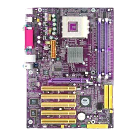
1-1 KT880E-GR/RL/R Mainboard Layout .................................9
1-2 Mainboard Specification Table ........................................... 10
1-3 Chipset System Block Diagram ............................................ 11
1-4 Mainboard Specifications and Features ............................ 12
1-4.1 CPU Socket ................................................................................... 12
1-4.2 System Chipsets ........................................................................... 12
1-4.3 Memory ......................................................................................... 12
1-4.4 BIOS ............................................................................................... 12
1-4.5 Accelerated Graphics Port (AGP) Interface ........................... 12
1-4.6 AC'97 Audio Codec on board .................................................... 13
1-4.7 Advanced System Power Management .................................... 13
1-4.8 Multi-I/O Functions .................................................................... 13
1-4.9 SATA RAID Interface ................................................................. 14
1-4.10 Expansion Slots .......................................................................... 14
1-4.11 Hardware Monitor on board ................................................... 14
1-4.12 LAN on board (for KT880E-RL only) ................................... 14
1-4.13 LAN on board (for KT880E-GR only) ................................... 14
1-4.14 Form Factor ................................................................................ 14
Chapter 2 Hardware Setup ..................................... 16
2-1 CPU Identification and Installation ................................... 17
2-1.1 CPU Identification Legends ....................................................... 17
2-1.2 CPU Installation with Socket 462 ............................................. 18
2-2 Memory Installation ............................................................. 19
2-2.1 Dual Channel Memory Features ............................................... 19
2-2.2 To Install DDR SDRAM Module .............................................. 19
2-3 AGP Slot Installation ............................................................ 20
Contents
4
Advertisement
Table of Contents

Subscribe to Our Youtube Channel
Related Manuals for SOLTEK SL-KT880E-GR


Summary of Contents for SOLTEK SL-KT880E-GR
-
Page 1: Table Of Contents
Contents Contents Chapter 1 Specification ..........8 1-1 KT880E-GR/RL/R Mainboard Layout .........9 1-2 Mainboard Specification Table ........... 10 1-3 Chipset System Block Diagram ..........11 1-4 Mainboard Specifications and Features ......12 1-4.1 CPU Socket ................... 12 1-4.2 System Chipsets ................12 1-4.3 Memory .................. - Page 2 Contents 2-4 IDE Connector Installation ..........21 2-5 SATA RAID Connectors Installation ......... 22 2-6 Floppy Drive Installation ............. 23 2-7 ATX Power Supply Installation .......... 24 2-8 Jumper Settings ..............25 2-8.1 How to tackle the Jumpers: ............26 2-8.2 JCLK1 &...
- Page 3 Contents 3-5.2 Verification .................. 48 3-6 LAN Driver Installation (for KT880E-GR/RL only) ..49 3-6.1 Installation ................... 49 3-6.2 Verification .................. 49 Chapter 4 AMI BIOS Setup ........50 4-1 About BIOS Setup ..............51 4-2 To Run BIOS Setup ............... 51 4-3 About CMOS ................
- Page 4 Contents 4-6.6.3 Hard Disk/Removable/ATAPI CDROM Drives ..... 76 4-6.7 Boot Security Features ............... 77 4-6.7.1 Supervisor Password ..............77 4-6.7.2 User Password ................77 4-6.7.3 Change Supervisor Password ........... 78 4-6.7.4 Change User Password .............. 79 4-6.7.5 Clear User Password ..............79 4-6.7.6 Boot Sector Virus Protection ............
-
Page 5: Chapter 1 Specification
SL-KT880E-GR/RL/R Chapter 1 Specification Introduction This mainboard features an integration of the powerful AMD proces- sors Athlon/Athlon XP/Duron and the North Bridge VIA Apollo KT880 plus South Bridge VT8237, with which the whole system performance supports 400/333/266 MHz system bus. -
Page 6: Kt880E-Gr/Rl/R Mainboard Layout
Chapter 1 Specification 1-1 KT880E-GR/RL/R Mainboard Layout VT6103 is for KT880E-RL with 10/100Mb data transfer VT6122 is for KT880E-GR with LAN Controller 10/100/1000Mb data transfer for KT880E-GR/RL only RJ45 Mouse JKB1 (on top) PS/2 Keyboard (underside) Fan1 USB0 (port) USB1 (port) Main Power +12V Power... -
Page 7: Mainboard Specification Table
SL-KT880E-GR/RL/R 1-2 Mainboard Specification Table KT880E-GR/RL/R Specifications and Features Socket 462 for AMD Athlon, Athlon XP, Duron CPU North Bridge VIA KT880, supporting 400/333/266 MHz FSB South Bridge VIA VT8237 BIOS AMI BIOS Supporting Dual Channel DDR 400/333/266 Memory SDRAM, up to 2GB in 2 DDR SDIMM slots... -
Page 8: Chipset System Block Diagram
Chapter 1 Specification 1-3 Chipset System Block Diagram Socket 462 for AMD CPUs System Bus 400/333/266MHz North Bridge Dual Channel System AGP 8X/4X AGP Slot Memory DDR 400/333/ VIA KT880 266 SDRAM Ultra V-Link 1066MB/Sec PCI Bus 5 PCI Slots 4 IDE ATA 133/100/66 Devices... -
Page 9: Mainboard Specifications And Features
SL-KT880E-GR/RL/R 1-4 Mainboard Specifications and Features 1-4.1 CPU Socket CPU Socket 462 (Socket A) on board, supporting AMD Athlon, Athlon XP and Duron processors and implementing 400/333/266/200MHz sys- tem bus 1-4.2 System Chipsets North Bridge KT880: • Managing and supporting 400/333/266/200MHz system Bus, AGP... -
Page 10: 1-4.6 Ac'97 Audio Codec On Board
Chapter 1 Specification 1-4.6 AC’97 Audio Codec on board AC’97 Audio Codec VIA VT1617 on board • Supporting 6-channel display of PCM audio output • 6 channel audio consists of Front Left, Front Right, Back Left, Back Right, Center and Subwoofer for complete surround sound effect •... -
Page 11: 1-4.9 Sata Raid Interface
• Hardware Monitor integrated in LPC I/O IT8705F, providing monitor- ing functions on hardware voltage, temperatures and fan speeds. • Utility Software Soltek Hardware Monitor for displaying monitor sta- tus is enclosed in Support CD for user’s installation. 1-4.12 LAN on board (for KT880E-RL only) PCI local bus single-chip Fast Ethernet Controller VT6103 on board: •... - Page 12 Chapter 1 Specification MEMO...
-
Page 13: Chapter 2 Hardware Setup
SL-KT880E-GR/RL/R Chapter 2 Hardware Setup To Get Things Ready for Hardware Setup ! 1. We recommend to install your CPU before any other components. For detailed installation instructions of processor, you can also refer to the pamphlet enclosed in your CPU package. -
Page 14: Cpu Identification And Installation
Chapter 2 Hardware Setup 2-1 CPU Identification and Installation 2-1.1 CPU Identification Legends XXXXXXXXXXX XXXXXXXXXXXX XXXXXXX XXXXXXXXX XXXXXXXXXXX XXXX .18 micron process CPU .13 micron process CPU AMD Athlon(Duron) AX 1900 D M T 3 C (1) (2) (3) (4) (5) (6) (7) Family / Architecture: A, AX, AXDA=AMD Athlon Processor D, DHD, DHM, DHL=AMD Duron Processor... -
Page 15: 2-1.2 Cpu Installation With Socket 462
SL-KT880E-GR/RL/R 2-1.2 CPU Installation with Socket 462 This mainboard is built with CPU Socket 462 supporting the AMD CPUs Athlon, Athlon XP and Duron: • Follow the steps described in this section to install CPU into the on- board Socket 462. -
Page 16: Memory Installation
Chapter 2 Hardware Setup 2-2 Memory Installation How to tackle with the memory Modules: • Make sure to unplug your Power Supply before adding or removing memory module. Failure to do so may cause severe damage to both your mainboard and the memory module. •... -
Page 17: Agp Slot Installation
SL-KT880E-GR/RL/R 2-3 AGP Slot Installation The AGP slot on board supports 1.5V AGP 8X/4X card only. A Rib is specifically added to the 8X/4X slot so as to match the AGP 8X/4X card. To insert a 3.3V AGP 2X card into the AGP 4X slot will damage the system chip and burn the 1.5V circuitry. -
Page 18: Ide Connector Installation
Chapter 2 Hardware Setup 2-4 IDE Connector Installation To install IDE Connector, you may connect the blue connector of IDE cable to the primary (IDE1) or secondary (IDE2) connector on board, and then connect the gray connector to your slave device and the black connector to your master device. -
Page 19: Sata Raid Connectors Installation
SL-KT880E-GR/RL/R 2-5 SATA RAID Connectors Installation 2 Serial ATA connectors for 2 SATA Hard Disks with RAID mode are supported by the South Bridge VIA VT8237. Please see Chapter 5 Disk Array Installation for detail RAID installaion. Mouse JKB1 (on top) -
Page 20: Floppy Drive Installation
Chapter 2 Hardware Setup 2-6 Floppy Drive Installation To install Floppy Drive, you should connect the end of Floppy Drive cable with single connector to the board, and connect the other end with two connectors to the floppy drives. Mouse JKB1 (on top) PS/2 Keyboard... -
Page 21: Atx Power Supply Installation
SL-KT880E-GR/RL/R 2-7 ATX Power Supply Installation +12V Power Connector Mouse JKB1 (on top) PS/2 Keyboard (underside) Fan1 USB0 (port) USB1 (port) Main Power +12V +12V +12V Power KT880 Main Power RJ45 (on top) USB2 (port) Connector USB3 (port) JAUD1 Fan4... -
Page 22: Jumper Settings
Chapter 2 Hardware Setup 2-8 Jumper Settings The following diagrams show the locations and settings of jumpers on the mainboard. JKB1 Keyboard/Mouse Wake-up 2-3 closed Enabled 1-2 closed (default) Disabled Mouse JKB1 JP1: (on top) Anti-burn Shield (ABSII) PS/2 Keyboard (underside) Fan1 (Overheated CPU Shutdown) -
Page 23: 2-8.1 How To Tackle The Jumpers
SL-KT880E-GR/RL/R 2-8.1 How to tackle the Jumpers: A 2-pin Jumper A 3-pin Jumper If a pin-header (of 2 or more pins) is designed in such a way that its pins can be closed or linked together to The conductor inside the cap set up a specific function, this header links two header-pins together. -
Page 24: 2-8.3 Jbat1: Clear Cmos
Chapter 2 Hardware Setup Further notes on CPU Overclocking: 1. If you have successfully booted system with or without CPU overclock, you still can do another CPU overclock in BIOS Setup. Please enter BIOS Setup, choose “Frequency/Voltage Control” menu, and take the “Use Linear”... -
Page 25: 2-8.4 Jp1: Anti-Burn Shield (Absii)
SL-KT880E-GR/RL/R 2-8.4 Jp1: Anti-burn Shield (ABSII) JP1: Anti-burn Shield (ABSII) (Overheated CPU Shutdown) (only for Athlon XP/Duron) 1-2 closed (default) Enabled 2-3 closed Disabled JP1 is designed to enable the overheat safeguard for some CPUs which are incorporated with a protective thermal diode. The latest AMD Athlon XP and Duron Morgan CPUs are incorporated with such thermal diode and can be protected by this function. -
Page 26: 2-8.5 Jkb1: Keyboard/Mouse Wake-Up
Chapter 2 Hardware Setup 2-8.5 JKB1: Keyboard/Mouse Wake-up JKB1 is designed to enable / disable the PS/2 Keyboard or PS/2 Mouse Wake-up (from suspend mode). Setting JKB1 to 1-2 closed will disable this function while setting JKB1 to 2-3 closed will enable this function. Yet users still have to choose the KB/Mouse Wake-up mode on BIOS. -
Page 27: Other Connectors Configuration
SL-KT880E-GR/RL/R 2-9 Other Connectors Configuration This section lists out all connectors configurations for users’ reference. 2-9.1 On-board FAN Connectors Mouse JKB1 (on top) Void PS/2 Keyboard (underside) Fan1 Sensor USB0 (port) +12V USB1 (port) +12V Main Power Sensor Conn. No Sensor... -
Page 28: 2-9.2 Usb Ports And Usb Pin-Headers
Chapter 2 Hardware Setup 2-9.2 USB Ports and USB Pin-headers This series provides four USB ports USB0 to USB3 on board sup- porting various USB devices. In addition, two USB pin-headers are added on board to provide expansion of four more optional USB ports by using two additional USB Cables. -
Page 29: 2-9.3 Chassis Back Panel Connectors
SL-KT880E-GR/RL/R 2-9.3 Chassis Back Panel Connectors A : PS/2 Mouse H : COM1 Connector B : USB 0 (port) : COM2 Connector (Optional) C : LPT1 Port : USB 2 (port) D : RJ45 (KT880E-GR/RL only) USB 3 (port) E : Line in/... -
Page 30: 2-9.5 Cd-Rom Audio Connectors (Cd-In1)
Chapter 2 Hardware Setup 2-9.5 CD-ROM Audio Connectors (CD-In1) CD-In1 is an audio connector connecting CD-ROM audio to mainboard. Mouse JKB1 (on top) PS/2 Keyboard (underside) Fan1 USB0 (port) USB1 (port) CD-ROM Audio Connector Main Power CD-In1 Pin Signal +12V Power KT880 RJ45 (on top) -
Page 31: 2-9.7 Thermal Connectors
SL-KT880E-GR/RL/R 2-9.7 Thermal Connectors Mouse JKB1 (on top) PS/2 Keyboard (underside) Fan1 USB0 (port) USB1 (port) RT1 is mounted with Thermal Resistor by default for detecting Main Power external CPU temperature. +12V Power KT880 RJ45 (on top) USB2 (port) USB3... -
Page 32: 2-9.9 Complex Pin-Header (Front Panel Connectors)
Chapter 2 Hardware Setup 2-9.9 Complex Pin-header (Front Panel Connectors) This complex Pin-header consists of the following connectors for vari- ous front panel supports. When you have fixed the mainboard to the case, join the connectors of this Complex Pin-header to the case Front Panel. - Page 33 SL-KT880E-GR/RL/R (1) Power Switch Connector: Connection: Connected to a momentary button or switch. Function: Manually switching the system between “On” and “Soft Off”. Pressing the momentary button for more than 4 seconds will also turn the system off. (2) IR Connector (Infrared Connector): Connection: Connected to Connector IR on board.
- Page 34 Chapter 2 Hardware Setup MEMO...
-
Page 35: Chapter 3 Software Setup
SL-KT880E-GR/RL/R Chapter 3 Software Setup Drivers, Utilities and Software Installation Support CD: This mainboard will be shipped with a Support CD which contains those necessary driver files, Application Softwares and some helpful utilities. It is a user-friendly, auto-run CD which will open itself up in a CD-ROM automatically. -
Page 36: To Open Up Support Cd
Chapter 3 Software Setup 3-1 To Open Up Support CD: 1. Please put the Support CD enclosed in your mainboard package into the CD-ROM drive. In a few seconds, the Main Menu will automatically appear, displaying the contents to be installed for this series: 2. -
Page 37: Via 4-In-1 Drivers Installation
SL-KT880E-GR/RL/R 3-2 VIA 4-IN-1 Drivers Installation 1. Following the procedures of opening the Support CD, click to “ VIA 4- in-1 Drivers” to proceed. 3. “VIA Service Pack README” 2 . T h e V I A S e r v i c e P a c k... - Page 38 Chapter 3 Software Setup 6. Select “Install VIA PCI IDE 7. Select “Install VIA AGP Driver” Driver” checkbox, then click the in turbo mode and press “Next” “Next” button to continue. button to continue. Next Next 8. After all these setup procedures have finished, you should restart your computer by clicking on “OK”...
-
Page 39: To Install Ac'97 Audio Driver
SL-KT880E-GR/RL/R 3-3 To Install AC’97 Audio Driver VIA AC97 Audio Codec VT1617 on board, AC’97 2.2 compatible, sup- porting 6 channel audio codec for PC multimedia systems. VIA AC’97 Audio Codec Driver is provided in Support CD for user’s installation. -
Page 40: 3-3.2 To Verify 6-Channel Audio
Chapter 3 Software Setup 3-3.2 To verify 6-channel Audio After installation of AC’97 6-channel Codec, you must configure the 5.1 Speaker connection to enable the 6-channel audio. 1. Connect your on-board Audio Connector to your 6-channel speakers as depicted in the figure below: Pale Blue Connector to Rear Speaker Pale Green Connector... - Page 41 SL-KT880E-GR/RL/R 3. At the “SPDIF & Speaker Configuration”, pick the item “6 Channel “ and “Smart 5.1Plus Enable” to activiate 6 channel configuration. Then close this window to finish configuration. 4. At finishing the Speakers Configuration, you can also click the “Speaker Test”...
-
Page 42: Usb 2.0 Driver Installation
Chapter 3 Software Setup 3-4 USB 2.0 Driver installation VIA USB V2.0 is already integrated on board. Its 480Mb/s transfer rate supports operating systems Windows 98SE/ME/2000/XP. USB2.0 Driver is typically for Windows 98SE/ME. For Windows 2000/XP, users can install their latest Service Pack instead of the USB2.0 driver to gain the USB2.0 support. - Page 43 SL-KT880E-GR/RL/R 3. Instantly, next screen will pop up to prompt you to select component. Select “Install USB Driver” and click “Next” button to continue. Next 4. The USB 2.0 Setup Program will then guide you through the whole driver setup until the “Finish” screen appears to prompt you to restart your system.
-
Page 44: Install Hardware Monitor Utility
Chapter 3 Software Setup 3-5 Install Hardware Monitor Utility 3-5.1 Installation Hardware Monitor is built on this mainboard. Its installation is pro- grammed to a fully automated mode on Windows 9X/Me/NT4/2000/ XP. Users can follow the model installation below for its installation on various Windows System. -
Page 45: 3-5.2 Verification
SL-KT880E-GR/RL/R 3-5.2 Verification 1. After installing Soltek Hardware Monitor, double click “SoltekHM” icon on the desktop to open the main window of the Soltek Hardware Doctor. 2.Then the pop-up screen will show all information about CPU Temperature, Fan Speed and various Voltages. -
Page 46: Lan Driver Installation (For Kt880E-Gr/Rl Only)
Chapter 3 Software Setup 3-6 LAN Driver Installation (for KT880E-GR/RL only) 3-6.1 Installation 1. Following the procedures of opening the Support CD, click to “ Onboard LAN Driver” to proceed. 2. Instantly, “The installation is completed” screen appears, indicating that LAN Driver setup is finished. -
Page 47: Chapter 4 Ami Bios Setup
SL-KT880E-GR/RL/R Chapter 4 AMI BIOS Setup THE BIOS BIOS stands for Basic Input and Output System. It was once called ROM BIOS when it was stored in a Read-Only Memory (ROM) chip Now manufacturers would like to store BIOS in EEPROM which means Electrically Erasable Programmable Memory. -
Page 48: About Bios Setup
Chapter 4 BIOS Setup 4-1 About BIOS Setup BIOS setup is an interactive BIOS program that you need to run when: 1. Changing the hardware of your system. (For example: installing a new Hard Disk etc.) 2. Modifying the behavior of your computer. (For example: changing the system time or date, or turning special features on or off etc.) 3. -
Page 49: To Update Bios
SL-KT880E-GR/RL/R 4-5 To Update BIOS • System BIOS is incorporated into a Flash memory component. Flash BIOS allows user to upgrade BIOS without the need to replace an EPROM component. • The Upgrade Utility can be loaded on a floppy diskette for upgrading saving, and verifying the system BIOS. - Page 50 Chapter 4 BIOS Setup Step 4. Under “ A “ prompt, type “ amiflash *.ROM “ and then press <Enter> to run BIOS update program. (*.ROM depends on your mainboard model and version code. Instead of typing “*”, you should type the specific file name for your specific mainboard).
-
Page 51: Bios Setup
SL-KT880E-GR/RL/R 4-6 BIOS SETUP --- CMOS Setup Utility 4-6.1 CMOS Setup Utility This mainboard comes with the AMI BIOS from American Megatrends Inc. Enter the CMOS Setup Utility Main Menu by: 1. Turn on or reboot your system. After a series of diagnostic checks, the following message will appear: PRESS <Del>... - Page 52 <F9>: “Optimized Defaults” alows user to load Optimal Defaults or not. Attention: The BIOS Setup is subject to constant update without further notice to users. It is necessary for users themselves to update onboard BIOS with the latest BIOS version provided in our web site: http://www.soltek.com.tw...
-
Page 53: 4-6.2 Standard Bios Features
SL-KT880E-GR/RL/R 4-6.2 Standard BIOS Features “Standard BIOS Features” allows users to configure Time and Date. This menu also displays system information. Run the Standard BIOS Features as follows: Choose “Standard BIOS Features” from the Main Menu and press <Enter>. The following screen will appear: CMOS Setup Utility - Copyright (C) 1985-2002, American Megatrends, Inc. -
Page 54: 4-6.3 Advanced Bios Features
Chapter 4 BIOS Setup 4-6.3 Advanced BIOS Features Advanced BIOS Features allows user to configure HDD, Floppy, Serial Port, Parallel Port etc..Run the Advanced BIOS Features as follows: Choose “Advanced BIOS Features” from the Main Menu and a screen with a list of options will appear: CMOS Setup Utility - Copyright (C) 1985-2002, American Megatrends, Inc. -
Page 55: 4-6.3.1 Ide Configuration
SL-KT880E-GR/RL/R 4-6.3.1 IDE Configuration Choose “IDE Configuration” in “Advanced BIOS Features” and press <Enter>. The following sub-screen will appear for IDE Devices configuration: IDE Configuration Help Item IDE Configuration OnBoard PCI IDE Controller Both Primary IDE Master Hard Disk Primary IDE Slave... - Page 56 Chapter 4 BIOS Setup 4-6.3.1-1 Primary/Secondary IDE Master/Slave Primary IDE Master Hard Disk Primary IDE Slave ATAPI CDROM Secondary IDE Master Not Detected Secondary IDE Slave Not Detected Third IDE Master Not Detected Fourth IDE Master Not Detected Press <Enter> to show the detected information of Primary/Secondary IDE Master/slave device(s).
-
Page 57: 4-6.3.2 Floppy Configuration
SL-KT880E-GR/RL/R 4-6.3.2 Floppy Configuration Choose “Floppy Configuration” in “Advanced BIOS Features” and press <Enter>. The following sub-screen will appear for configuration: Floppy Configuration Help Item Floppy Configuration Floppy A 1.44 MB 3.5 in Floppy B Disabled : Move Enter : Select... -
Page 58: 4-6.3.3 Super Io Configuration
Chapter 4 BIOS Setup 4-6.3.3 Super IO Configuration Choose “SuperIO Configuration” in “Advanced BIOS Features” and press <Enter>. The following sub-screen will appear for configuration: SuperIO Configuration Help Item Configure ITE8705 Super IO Chipset OnBoard Floppy Controller Enabled Serial Port1 Address 3F8/IRQ4 Serial Port2 Address 2F8/IRQ3... - Page 59 SL-KT880E-GR/RL/R Parallel Port Address Allows you to configure Parallel Port Address. Choices: Disabled; 378; 278; 3BC; Parallel Port Mode If Parallel Port Address is set 378/278/3BC, Parallel Port Mode appears to allow you to set the Parallel Port Mode. The choices are: Normal;...
-
Page 60: 4-6.3.4 Hardware Health Configuration
Chapter 4 BIOS Setup 4-6.3.4 Hardware Health Configuration Choose “Hardware Health Configuration” in “Advanced BIOS Fea- tures” and press <Enter>. The following sub-screen will appear for configuration: Hardware Health Configuration Help Item Hardware Health Configuration ABS II Temperature : 43˚C/111˚F ABS II Shut Down Temperature : 85˚C/185˚F CPU Temperature... -
Page 61: 4-6.3.5 Acpi Configuration
SL-KT880E-GR/RL/R 4-6.3.5 ACPI Configuration Choose “ACPI Configuration” in “Advanced BIOS Features” and press <Enter>. The following sub-screen will appear for ACPI configuration: ACPI Configuration Help Item ACPI Settings General ACPI ACPI Aware O/S Configuration settings General ACPI Configuration Press Enter ACPI Aware O/S Allows you to enable ACPI Aware O/S function if your O/S supports ACPI. -
Page 62: 4-6.3.6 Power Manager Configuration
Chapter 4 BIOS Setup 4-6.3.6 Power Manager Configuration Choose “Power Manager Configuration” in “Advanced BIOS Features” and press <Enter>. The following sub-screen will appear for configuration: Power Management Help Item APM Configuration Enable or disable APM. Power Management/APM Enabled Power Button mode On/Off Restore on AC Power Loss Last State... -
Page 63: 4-6.3.7 Usb Configuration
SL-KT880E-GR/RL/R Advanced Resume Events Controls Resume on Ring Allows you to enable / disable the Resume on Ring Signal function. An input signal on the serial Ring Indicator (RI) Line (in other words, an incoming call on the modem) awakens the system from a soft off state. -
Page 64: 4-6.3.8 Clock Generator Configuration
Chapter 4 BIOS Setup 4-6.3.8 Clock Generator Configuration Choose “Clock Generator Configuration” in “Advanced BIOS Features” and press <Enter>. The following sub-screen will appear for configuration: Clock Generator Configuration Help Item Configure ICS ICS94230 Clock Generator CPU Linear Frequency Enabled CPU Frequency Setting AGP/PCI Clock (Mhz) 66.67/33.33... -
Page 65: 4-6.3.9 Cpu/Voltage Configuration
SL-KT880E-GR/RL/R 4-6.3.9 CPU/Voltage Configuration Choose “CPU/Voltage Configuration” in “Advanced BIOS Features” and press <Enter>. The following sub-screen will appear for configuration: CPU/Voltage Configuration Help Item CPU Voltage Control Auto DIMM Voltage Control 2.5V VCC2.5V Voltage Control 2.5V AGP Voltage Control 1.5V... -
Page 66: 4-6.4 Advanced Chipset Features
Chapter 4 BIOS Setup 4-6.4 Advanced Chipset Features Advanced Chipset Features is used to modify the values of chipset buffers. These buffers control the system options. Run the Advanced Chipset Features as follows: Choose “Advanced Chipset Features” from the Main Menu and a list of option will appear: CMOS Setup Utility - Copyright (C) 1985-2002, American Megatrends, Inc. -
Page 67: 4-6.4.1 Northbridge Configuration
SL-KT880E-GR/RL/R 4-6.4.1 NorthBridge Configuration Choose “NorthBridge Configuration” in “Advanced Chipset Features” and press <Enter>. The following sub-screen will appear for configuration: NorthBridge VIA KT880 Configuration Help Item Top Performance Disable ******** DRAM Timing ******** DRAM Clock By SPD DRAM Timing... - Page 68 Chapter 4 BIOS Setup DRAM Bus Selection Allows you to select DRAM Bus. Choices: Auto; Single Channel; Dual Channel Primary Graphics Adapter To select the Primary Graphics Adapter. Choices: AGP; PCI VLink 8x Supported Allows you to enable / disable VLink 8x mode. AGP Mode Allows you to select the AGP Mode on board.
-
Page 69: 4-6.4.2 Southbridge Configuration
SL-KT880E-GR/RL/R 4-6.4.2 SouthBridge Configuration Choose “SouthBridge Configuration” in “Advanced Chipset Features” and press <Enter>. The following sub-screen will appear for configuration: SouthBridge Configuration South Bridge Chipset Configuration Help Item OnBoard SATA-IDE RAID OnBoard LAN (optional) Enabled OnBoard AC’97 Audio Enabled... -
Page 70: 4-6.5 Pci/Pnp Resource Management
Chapter 4 BIOS Setup 4-6.5 PCI/PNP Resource Management PCI/PNP Resource Management allows you to modify the system’s power saving functions. Choose “PCI/PNP Resource Management” from the Main Menu and a screen with a list of options will appear: CMOS Setup Utility - Copyright (C) 1985-2002, American Megatrends, Inc. PCI/PNP Resource Management Help Item Advanced PCI/PNP Settings... -
Page 71: 4-6.6 Boot Configuration Setup
SL-KT880E-GR/RL/R 4-6.6 Boot Configuration Setup Boot Configuration Setup allows you to modify the system’s boot settings with the onboard devices. Choose “Boot Configuration Setup” from the Main Menu and a screen with a list of options will appear: CMOS Setup Utility - Copyright (C) 1985-2002, American Megatrends, Inc. -
Page 72: 4-6.6.1 Boot Settings Configuration
Chapter 4 BIOS Setup 4-6.6.1 Boot Settings Configuration Choose “Boot Settings Configuration” in “Boot Configuration Setup” and press <Enter>. The following items will appear for onfiguration: Boot Configuration Setup Help Item Boot Settings Configuration Quick Boot Enabled AddOn ROM Display Mode Force BIOS Bootup Num-Lock PS/2 Mouse Support... -
Page 73: 4-6.6.2 Boot Device Priority
SL-KT880E-GR/RL/R 4-6.6.2 Boot Device Priority Choose “Boot Device Priority” in “Boot Configuration Setup” and press <Enter>. The bootable devices installed on board will appear and are allowed to assign the Boot Priority. Boot Device Priority Help Item Boot Device Priority... -
Page 74: 4-6.7 Boot Security Features
Chapter 4 BIOS Setup 4-6.7 Boot Security Features Boot Security Features allows you to modify the system’s boot security settings. Choose “Boot Security Features” from the Main Menu and a screen with a list of options will appear: CMOS Setup Utility - Copyright (C) 1985-2002, American Megatrends, Inc. Boot Security Features Security Settings Help Item... -
Page 75: 4-6.7.3 Change Supervisor Password
SL-KT880E-GR/RL/R 4-6.7.3 Change Supervisor Password This option allows you to set a new Supervisor password for the system: 1. Choose “Change Supervisor Password” in the “BIOS Security Fea- tures” and press <Enter>. Then the following message appears: [ Enter new supervisor password ] 2. -
Page 76: 4-6.7.4 Change User Password
Chapter 4 BIOS Setup 4-6.7.4 Change User Password This option allows you to set a new User password for the system: 1. Choose “Change User Password” in the “BIOS Security Features” and press <Enter>. Then the following message appears: [ Enter New Password ] 2. -
Page 77: 4-6.7.6 Boot Sector Virus Protection
SL-KT880E-GR/RL/R Password Check Allows you to set BIOS to check up password with a password prompt at BIOS Setup or whenever restarting system. This option will appear when you have set Supervisor Pass- word or User Password. Choices: Setup; Always 4-6.7.6 Boot Sector Virus Protection... -
Page 78: 4-6.9 Discard Changes ( And Exit )
Chapter 4 BIOS Setup 4-6.9 Discard Changes ( and Exit ) Discard Changes option allows you to exit (or not exit) the Setup Utility without saving the modifications that you have specified. Highlight this option on the Main Menu and press <Enter> and the following message appears: [ Discard Changes (and exit setup?)] [OK]... -
Page 79: Chapter 5 Via Sata Raid Setup
SL-KT880E-GR/RL/R Chapter 5 VIA SATA RAID Setup THE VIA SATA RAID Controller VT8237 & RAID BIOS VIA RAID (Redundant Array of Independent Disks) Controller is built in the South Bridge VT8237. With this RAID Controller, the VIA SATA RAID BIOS is built into the system to help configure the Redundant Disk Array. -
Page 80: About Disk Array
Chapter 5 SATA RAID 5-0 About Disk Array 5-0-1 Disk Array Interpretation A “Disk Array” is formed from a group of 2 or more disk drives with the RAID (Redundent Array of Independent Disks) technology. The aim of a Disk Array is to provide better perfornance and/or data fault tolerance. 5-0-2 Disk Array Member The individual disk drive in an array is called a “member”. -
Page 81: Enable Sata Raid In System Bios (Vt8237)
SL-KT880E-GR/RL/R 5-1 Enable SATA RAID in System BIOS (VT8237) Mouse JKB1 (on top) PS/2 Keyboard (underside) Fan1 USB0 (port) USB1 (port) Main Power +12V Power Chipset VT8237 supporting KT880 RJ45 (on top) USB2 (port) SATA RAID Interfaces. USB3 (port) JAUD1... -
Page 82: To Enter Via Tech. Raid Bios Setup
Chapter 5 SATA RAID 5-2 To Enter VIA Tech. RAID BIOS Setup Boot the KT880E-R/RL/GR system with “RAID Interface” enabled in system BIOS Setup and watch for the following initial screen to appear: VIA Technologies, Inc. VIA VT8237 Serial RAID BIOS Setting Utility V2.10 Copyright (C) VIA Technologies, Inc. -
Page 83: Using Via Raid Bios Setup To Create Disk Array
SL-KT880E-GR/RL/R 5-3 Using VIA RAID BIOS Setup to Create Disk Array (5-3-1) When you press <Enter> on the “Create Array” bar, the follow- ing screen shows up. Press <Enter>on this bar to select the RAID mode. VIA Tech. VT8237 SATA RAID BIOS Ver 2.10... - Page 84 Chapter 5 SATA RAID (5-3-3) The following screen shows that RAID 0 (Striping) is selected. Now, use the “Arrow” key to mark up the “Auto Setup For Performance” bar. VIA Tech. VT8237 SATA RAID BIOS Ver 2.10 Create A RAID array with the Auto Setup For Performance hard disks attatched to VIA RAID Array Mode RAID 0 (Striping)
- Page 85 SL-KT880E-GR/RL/R (5-3-5) Instantly, the RAID 0 Striping mode is set up and shown on the screen. Then press <Escape> key to exit the screen. VIA Tech. VT8237 SATA RAID BIOS Ver 2.10 Set/Clear bootable array Create Array Delete Array Create/Delete Spare...
- Page 86 Chapter 5 SATA RAID (5-3-7) Instantly, the Master Hard Disk is marked up. Press <Enter> on the screen to set up the “Boot Disk”. VIA Tech. VT8237 SATA RAID BIOS Ver 2.10 Set/Clear bootable array Create Array Delete Array Create/Delete Spare : View Array/disk Status Select Boot Array...
-
Page 87: Using Via Raid Bios Setup To Change Array Mode
SL-KT880E-GR/RL/R 5-4 Using VIA RAID BIOS Setup to change Array mode (5-4-1) If you wants to change the RAID mode, say, from RAID 0 to RAID 1, you must return to the Initial RAID BIOS Setup screen. Then, press the “Arrow” key to mark the “Delete Array” bar and press <Enter>. - Page 88 Chapter 5 SATA RAID (5-4-3) When the message “The selected array will be destroied..” appears on screen, press <Y> key to continue. VIA Tech. VT8237 SATA RAID BIOS Ver 2.10 Delete a RAID array contain the Create Array hard disks attatched to VIA RAID Delete Array controller Create/Delete Spare...
-
Page 89: To Install Sata Raid Driver
SL-KT880E-GR/RL/R 5-5 To Install SATA RAID Driver SATA-RAID Driver is incorporated in Support CD/Floppy Diskette for user’s installation. This driver is intended for both SATA and SATA RAID installation. 5-5-1 To Install SATA RAID Driver on Windows 2000/XP (1) Get ready the Floppy Diskette holding the RAID Driver. -
Page 90: To Install Sata Raid Driver On Windows 98Se/Me
Chapter 5 SATA RAID 5-5-2 To Install SATA RAID Driver on Windows 98SE/ME (1) Get ready the Floppy Diskette holding the SATA RAID Driver. (2) Check that SATA Hard Disks are connected properly to the SATA Connectors. (3) Start your system and use RAID BIOS Setup Utility to configure RAID 0 or RAID 1 to the hard disks. - Page 91 SL-KT880E-GR/RL/R (11) In the “Update device Driver Wizard” screen, click “Next” to continue until you see a dialog box asking you to “Specify a location” for the driver. You should now insert the SATARAID Driver CD/Diskette into CD-ROM/Drive A. (12) As illustrated in the picture below, check the item “Specify a location”...
- Page 92 Chapter 5 SATA RAID MEMO...
Need help?
Do you have a question about the SL-KT880E-GR and is the answer not in the manual?
Questions and answers