Table of Contents
Advertisement
Quick Links
Contents
Chapter 1 Specification ............................................. 8
1-1 K890-754G Mainboard Layout .............................................. 9
1-2 Mainboard Specification Table ........................................... 10
1-3 Chipset System Block Diagram ............................................ 11
1-4 Mainboard Specifications and Features ............................ 12
1-4.1 CPU Socket ................................................................................... 12
1-4.2 System Chipsets ........................................................................... 12
1-4.3 Memory ......................................................................................... 12
1-4.4 BIOS ............................................................................................... 12
1-4.5 PCI Express Interface ................................................................. 13
1-4.6 AC'97 Audio Codec on board .................................................... 13
1-4.7 Advanced System Power Management .................................... 13
1-4.8 SATA RAID Interface ................................................................. 13
1-4.9 Multi-I/O Functions .................................................................... 14
1-4.10 Gigabit Ethernet on board ....................................................... 14
1-4.11 Hardware Monitor integrated ................................................. 14
1-4.12 Form Factor ................................................................................ 14
Chapter 2 Hardware Setup ..................................... 16
2-1 CPU Installation with Socket 754 ....................................... 17
2-2 Memory Installation ............................................................. 18
2-2.1 To Install DDR SDRAM Module .............................................. 18
2-2.2 DIMM Powered on ...................................................................... 18
2-3 PCI Express Slot Installation .............................................. 19
2-4 IDE Connector Installation ................................................. 20
2-5 SATA / RAID Connectors ..................................................... 21
2-6 Floppy Drive Installation ..................................................... 22
2-7 ATX Power Supply Installation .......................................... 23
2-8 Jumper Setting ....................................................................... 24
2-8.0 How to tackle the Jumpers: ....................................................... 25
2-8.1 JBAT1: Clear CMOS .................................................................. 25
2-8.2 JKB1: Keyboard/Mouse Wake-up ............................................ 26
2-8.3 LJP1: On-board LAN Controller Select ................................. 26
Contents
4
Advertisement
Table of Contents

Subscribe to Our Youtube Channel
Related Manuals for SOLTEK SL-K890-754G


Summary of Contents for SOLTEK SL-K890-754G
-
Page 1: Table Of Contents
Contents Contents Chapter 1 Specification ..........8 1-1 K890-754G Mainboard Layout ..........9 1-2 Mainboard Specification Table ........... 10 1-3 Chipset System Block Diagram ..........11 1-4 Mainboard Specifications and Features ......12 1-4.1 CPU Socket ................... 12 1-4.2 System Chipsets ................12 1-4.3 Memory .................. - Page 2 Contents 2-9 Other Connectors Configuration ........27 2-9.1 On-board FAN Connectors ............27 2-9.2 USB Ports and USB Pin-headers ..........28 2-9.3 Chassis Back Panel Connectors ..........29 2-9.4 PS/2 Mouse , PS/2 Keyboard, SPDIF In/Out connector ..29 2-9.5 RJ45 Connector ................30 2-9.6 CD-ROM Audio Connectors (CD_In1) ........
- Page 3 Contents 4-6.5.2. VIA OnChip PCI Device: ............63 4-6.5.3. Super IO Device: ............... 63 4-6.6 Power Management Setup ............64 4-6.7 PnP / PCI Configuration ............67 4-6.8 SmartDoc Anti-Burn Shield ............69 4-6.9 CPU Ratio/Voltage Control ............70 4-6.10 Load Optimized Defaults ............71 4-6.11 Set Supervisor / User Password ..........
- Page 4 Contents Memo...
-
Page 5: Chapter 1 Specification
SL-K890-754G Chapter 1 Specification Introduction This mainboard features an integration of the powerful processors AMD Athlon 64 754 and the North Bridge VIA K8T890 plus South Bridge VT8237R, with which the whole system performance supports HyperTransport Bus up to 800MHz. -
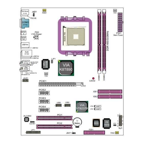
Page 6: K890-754G Mainboard Layout
Chapter 1 Specification 1-1 K890-754G Mainboard Layout PS/2 Mouse JKB1 PS/2 KB COM1 SPDIF +12V Power Main Power SPDIF USB Port USB Port RJ45 USB Port USB Port LJP1 K8T890 JAUD1 LED2 PCIE1 PCIE2 IDE1 IDE2 PCIE3 USB2 USB3 ATA2 PCIE4 VT8237R ATA1... -
Page 7: Mainboard Specification Table
SL-K890-754G 1-2 Mainboard Specification Table K890-754G Specifications and Features Socket 754 for AMD Athlon 64 CPUs North Bridge VIA K8T890, supporting up to 800MHz Hyper Transport South Bridge VIA VT8237R Supported by Athlon 64 CPU for DDR 400/333 Memory SDRAM, up to 2GB in 2 DIMM slots... -
Page 8: Chipset System Block Diagram
Chapter 1 Specification 1-3 Chipset System Block Diagram DDR 400/333 Socket 754 SDRAM System Memory AMD Athlon 64 HyperTransport Link 1 PCI Express-x16 PCI E-x16 card North Bridge (Graphics) VIA K8T890 3 PCI Express-x1 PCI E-x1 cards (including LAN) 8x V-Link 533MB/Sec ATA 133/100/66 4 IDE... -
Page 9: Mainboard Specifications And Features
SL-K890-754G 1-4 Mainboard Specifications and Features 1-4.1 CPU Socket CPU Socket 754 on board, supporting AMD Athlon 64 processors, imple- menting up to 800MHz Hyper Transport Speed (System Bus) designed to be capable of operating up to 2000MT/s with a resulting bandwidth of up to 8 Gbytes/s and integrated Memory Controller which supports DDR 400/333MHz SDRAM. -
Page 10: 1-4.5 Pci Express Interface
Chapter 1 Specification 1-4.5 PCI Express Interface 1PCI Express-x16 slot integrated, supporting: • a raw bit-rate of 2.5 Gb.s on the data pins, resulting in a real band- width per pair of 250MB/s. • Enhanced Addressing Machanism • PCIE Graphics / LAN card etc. (not supporting AGP card) 3 PCI Express-x1 slots integrated supporting PCIE LAN card etc. -
Page 11: 1-4.9 Multi-I/O Functions
1-4.11 Hardware Monitor integrated • Hardware Monitor integrated, providing monitoring functions on hard- ware voltage, temperatures and fan speeds. • Utility Software Soltek Hardware Monitor for displaying monitor sta- tus is enclosed in Support CD for user’s installation. 1-4.12 Form Factor •... - Page 12 Chapter 1 Specification Memo...
-
Page 13: Chapter 2 Hardware Setup
SL-K890-754G Chapter 2 Hardware Setup To Get Things Ready for Hardware Setup ! 1. We recommend to install your CPU before any other components. For detailed installation instructions of processor, you can also refer to the pamphlet enclosed in your CPU package. -
Page 14: Cpu Installation With Socket 754
Chapter 2 Hardware Setup 2-1 CPU Installation with Socket 754 This series is built with CPU Socket 754 supporting the AMD CPUs Athlon 64: 2. Pull up the lever to 1. Socket 754 supported by a cooling Fan Base. release socket lock. Socket 754 Pull up Lever Socket 754 Lever... -
Page 15: Memory Installation
SL-K890-754G 2-2 Memory Installation 2-2.1 To Install DDR SDRAM Module • Make sure to unplug your Power Supply before adding or removing memory module. Failure to do so may cause severe damage to both your mainboard and the memory module. -
Page 16: Pci Express Slot Installation
Chapter 2 Hardware Setup 2-3 PCI Express Slot Installation 1) X16 PCI Express Slot is built on board for PCI Express Graphics card attachment, supporting a raw bit-rate of 2.5Gb/s on the data pins. It does not support AGP 1X/2X/4X/8X card 2) 3 slots of x1 PCI Express is also supported by North Bridge, compliant with PCI Express Base Specification, Revision 1.0a for PCI Express cards (including LAN). -
Page 17: Ide Connector Installation
SL-K890-754G 2-4 IDE Connector Installation To install IDE Connector, you may connect the blue connector of IDE cable to the primary (IDE1) or secondary (IDE2) connector on board, and then connect the gray connector to your slave device and the black connector to your master device. -
Page 18: Sata / Raid Connectors
Chapter 2 Hardware Setup 2-5 SATA / RAID Connectors 2 Serial ATA connectors for 2 SATA/RAID Hard Disks are supported by the South Bridge VIA VT8237R. Please see Chapter 5 Disk Array In- stallation for detail RAID installaion. PS/2 Mouse JKB1 PS/2 KB COM1... -
Page 19: Floppy Drive Installation
SL-K890-754G 2-6 Floppy Drive Installation To install Floppy Drive, you should connect the end of Floppy Drive cable with single connector to the board, and connect the other end with two connectors to the floppy drives. PS/2 Mouse JKB1 PS/2 KB... -
Page 20: Atx Power Supply Installation
Chapter 2 Hardware Setup 2-7 ATX Power Supply Installation Main Power Connector PS/2 Mouse JKB1 +12V PS/2 KB COM1 PWR OK SPDIF +12V Power Main Power SPDIF USB Port USB Port RJ45 PS ON# USB Port USB Port LJP1 +3.3V -12V K8T890 +3.3V... -
Page 21: Jumper Setting
SL-K890-754G 2-8 Jumper Setting The following diagrams show the locations and settings of jumper blocks on the mainboard. JKB1: Keyboard/Mouse Wake Up 1-2 closed (default) Keyboard/Mouse Wake Up Disabled 2-3 closed Keyboard/Mouse Wake Up Enabled PS/2 Mouse JKB1 PS/2 KB... -
Page 22: 2-8.0 How To Tackle The Jumpers
Chapter 2 Hardware Setup 2-8.0 How to tackle the Jumpers: A 2-pin Jumper A 3-pin Jumper If a pin-header (of 2 or more pins) is designed in such a way that its pins can be closed or linked together to The conductor inside the cap set up a specific function, this header links two header-pins together. -
Page 23: 2-8.2 Jkb1: Keyboard/Mouse Wake-Up
SL-K890-754G 2-8.2 JKB1: Keyboard/Mouse Wake-up JKB1 is designed to enable / disable the JKB1: PS/2 Keyboard or PS/2 Mouse Wake- Keyboard/Mouse Wake Up up (from suspend mode). Setting JKB1 to 1-2 closed will disable this function 1-2 closed (default) while setting JKB1 to 2-3 closed will... -
Page 24: Other Connectors Configuration
Chapter 2 Hardware Setup 2-9 Other Connectors Configuration This section lists out all connectors configurations for users’ reference. 2-9.1 On-board FAN Connectors PS/2 Mouse JKB1 Void PS/2 KB Sensor COM1 +12V +12V SPDIF +12V Power Main Power SPDIF USB Port USB Port Sensor Conn. -
Page 25: 2-9.2 Usb Ports And Usb Pin-Headers
SL-K890-754G 2-9.2 USB Ports and USB Pin-headers This Mainboard provides 4 USB ports on board supporting various USB devices. In addition, 2 USB pin-headers are added on board to provide expansion of 4 more optional USB ports by using 2 additional USB Cables. -
Page 26: 2-9.3 Chassis Back Panel Connectors
Chapter 2 Hardware Setup 2-9.3 Chassis Back Panel Connectors K(middle) L(bottom) A : PS/2 Mouse : USB port B : COM1 Connector J : 2 USB ports C : S/PDIF In K : Line Out /Front Speaker D : S/PDIF Out E : USB port L : Microphone Input F : RJ45 Connector... -
Page 27: 2-9.5 Rj45 Connector
SL-K890-754G 2-9.5 RJ45 Connector One RJ45 connector is on board for LAN connection, supporting 10/ 100/1000Mb data transfer. Orange LED blinks to indicate Yellow LED “On” to indicate that data transmission is Network hub is in connection undergoing in 1000 Base T with the system. -
Page 28: 2-9.7 Thermal Detectors
Chapter 2 Hardware Setup 2-9.7 Thermal Detectors PS/2 Mouse JKB1 PS/2 KB COM1 SPDIF +12V Power Main Power SPDIF USB Port USB Port RJ45 USB Port USB Port LJP1 K8T890 JAUD1 LED2 PCIE1 PCIE2 IDE1 IDE2 PCIE3 USB3 USB2 ATA2 PCIE4 VT8237R ATA1... -
Page 29: 2-9.9 Complex Pin-Header (Front Panel Connectors)
SL-K890-754G 2-9.9 Complex Pin-header (Front Panel Connectors) This complex Pin-header consists of the following connectors for vari- ous front panel supports. When you have fixed the mainboard to the case, join the connectors of this Complex Pin-header to the case Front Panel. -
Page 30: 2-9.10 Printer Port: Lpt1
Chapter 2 Hardware Setup 2-9.10 Printer Port: LPT1 LPT1 is a parallel printer port. PS/2 Mouse JKB1 LPT1: Printer Port PS/2 KB COM1 Pin Assignment SPDIF +12V Power Main Power SPDIF Pin 1 STROBE# Pin 14 AUTOFD# Pin 2 LPTDD0 USB Port Pin 15 ERROR# USB Port... -
Page 31: Chapter 3 Software Setup
SL-K890-754G Chapter 3 Software Setup Drivers, Utilities and Software Installation Support CD: This mainboard will be shipped with a Support CD which contains those necessary driver files, Application Softwares and some helpful utilities. It is a user-friendly, auto-run CD which will open itself up in a CD-ROM automatically. -
Page 32: To Open Up Support Cd
Chapter 3 Software Setup 3-1 To Open Up Support CD: 1. Please put the Support CD enclosed in your mainboard package into the CD-ROM drive. In a few seconds, the Main Menu will automatically appear, displaying the contents to be installed for this series: 2. -
Page 33: Via 4-In-1 Drivers Installation
SL-K890-754G 3-2 VIA 4-IN-1 Drivers Installation 1. Following the procedures of opening the Support CD, click to “ VIA 4- in-1 Drivers” to proceed. 3. “VIA Service Pack README” 2 . T h e V I A S e r v i c e P a c k... - Page 34 Chapter 3 Software Setup 6. Select “Install VIA PCI IDE 7. Select “Install VIA AGP Driver” Driver” checkbox, then click the in turbo mode and press “Next” “Next” button to continue. button to continue. Next Next 8. After all these setup procedures have finished, you should restart your computer by clicking on “OK”...
-
Page 35: Usb 2.0 Driver Installation
SL-K890-754G 3-3 USB 2.0 Driver installation VIA USB V2.0 is already integrated on board. Its 480Mb/s transfer rate supports operating systems Windows 98SE/ME/2000/XP. USB2.0 Driver is typically for Windows 98SE/ME. For Windows 2000/XP, users can install their latest Service Pack instead of the USB2.0 driver to gain the USB2.0 support. - Page 36 Chapter 3 Software Setup 3. Instantly, next screen will pop up to prompt you to select component. Select “Install USB Driver” and click “Next” button to continue. Next 4. The USB 2.0 Setup Program will then guide you through the whole driver setup until the “Finish”...
-
Page 37: Ac'97 Audio Driver Installation
SL-K890-754G 3-4 AC’97 Audio Driver Installation RTL ALC850 8-channel AC97 Audio Codec on board, AC’97 2.3 compat- ible stereo audio code for PC multimedia systems. AC’97 Audio Codec Driver is provided in Support CD for user’s installation. 3-4.1 Installing AC’97 8-channel Audio Driver 1. -
Page 38: 3-4.2 Verifying 8-Channel Audio
Chapter 3 Software Setup 3-4.2 Verifying 8-channel Audio After installation of AC’97 8-channel Codec, you must configure the 7.1 Speaker connection to enable the 8-channel audio. 1. Connect your on-board Audio Connector to your 8-channel speakers as depicted in the figure below: Black Connector Blue Connector To Rear Speaker Out... - Page 39 SL-K890-754G 3. The AC’97 Audio Configuration” screen will pop out. Clikc the “Speaker Configuration” bar with your mouse. 4. Instantly, the “Speaker Configuration” screen will pop out. Pick the items “8-channelSpeaker” and then click on the Auto Test button. Instantly, the Speaker Auto-test starts until all speakers installed are...
-
Page 40: Lan Driver Installation
Chapter 3 Software Setup 3-5 LAN Driver Installation 1. Following the procedures of opening the Support CD, click to “ Onboard LAN Driver” to proceed. 2. Instantly, the “InstallShield Wizard” pop out to start Gigabit LAN / Fast Ethernet NIC LAN setup. -
Page 41: Install Hardware Monitor Utility
SL-K890-754G 3-6 Install Hardware Monitor Utility 3-6.1 Installation Hardware Monitor is built on this mainboard. Its installation is pro- grammed to a fully automated mode on Windows 9X/Me/NT4/2000/ XP. Users can follow the model installation below for its installation on various Windows System. -
Page 42: 3-6.2 Verification
Chapter 3 Software Setup 3-6.2 Verification 1. After installing Soltek Hardware Monitor, double click “SoltekHM” icon on the desktop to open the main window of the Soltek Hardware Doctor. 2.Then the pop-up screen will show all information about CPU Temperature, Fan Speed and various Voltages. -
Page 43: Chapter 4 Bios Setup
SL-K890-754G Chapter 4 BIOS Setup THE BIOS BIOS performs the following functions: 1. Initializing and testing hardware in your computer (a process called “POST”, for Power On Self Test). 2. Loading and running your operating system. 3. Helping your operating system and application programs manage your PC hardware by means of a set of routines called BIOS Run- Time Service. -
Page 44: About Bios Setup
Chapter 4 BIOS Setup 4-1 About BIOS Setup BIOS setup is an interactive BIOS program that you need to run when: 1. Changing the hardware of your system. (For example: installing a new Hard Disk etc.) 2. Modifying the behavior of your computer. (For example: changing the system time or date, or turning special features on or off etc.) 3. -
Page 45: To Update Bios
BIOS. • Please follow the steps below for updating the system BIOS: Step 1. Please visit Soltek website: www.soltek.com.tw, download the .zip files of the latest BIOS and BIOS-update utility into your hard disk for your mainboard. - Page 46 Chapter 4 BIOS Setup BIOS Update Illustration: (1) Executing the “awdflash.exe k8AV2008.bin” in DOS system, Award Flash Memory Writer Start Screen appears: To input BIOS file name. AwardBIOS Flash Utility V8.24F (C)Phoenix Technologies Ltd. All Rights Reserved For K8T800-8237-6A7L0SAAC-00 Date: 09/18/2003 File Name to Program : K8AV2008.BIN Message: Input the (BIOS) file name (2) Press Y if you want to back up your old BIOS,.
- Page 47 SL-K890-754G (4) Updating is in progress. Do not turn off power at this moment. AwardBIOS Flash Utility V8.24F (C)Phoenix Technologies Ltd. All Rights Reserved For K8T800-8237-6A7L0SAAC-00 Date: 09/18/2003 Flash Type - SST 39SF020 /5V File Name to Program : k8av2008.bin...
-
Page 48: Bios Setup
Chapter 4 BIOS Setup 4-6 BIOS SETUP --- CMOS Setup Utility Warning and Tips: If changing CMOS Configuration causes difficulty in rebooting system, you can take the following measures: 1. At pressing the power button to reboot, press the “Insert” key at the same time. - Page 49 SL-K890-754G 3. When one main item of the Main Menu is chosen and clicked on, its submenu will appear to display the related items and options. On the other hand, a list of operation guide will appear at the end of the...
-
Page 50: 4-6.2 Standard Cmos Setup
Chapter 4 BIOS Setup 4-6.2 Standard CMOS Setup Standard CMOS Setup records some basic system hardware configuration and sets the system clock and error handling. You only need to modify the configuration values of this option if you want to change your system hardware configuration or when the data stored in the CMOS memory gets lost or damaged. - Page 51 SL-K890-754G Date (mm:dd:yy) The BIOS determines the day of the week from the other date information. This field is for information only. Press the left or right arrow key to move to the desired field (date, month, year). Press the PgUp or PgDn key to increment the setting, or type the desired value into the field.
- Page 52 Chapter 4 BIOS Setup Drive A / Drive B Select this field to the type(s) of floppy disk drive(s) installed in your system. The choices are: 360KB, 5.25 in. 1.2MB, 5.25 in. 720KB, 3.5 in. 1.44MB, 3.5 in. 2.88MB, 3.5 in. None Video Select the type of primary video subsystem in your computer.
-
Page 53: 4-6.3 Advanced Bios Features
SL-K890-754G 4-6.3 Advanced BIOS Features Advanced BIOS Features improves your system performance or sets up system features according to your preference. Choose “Advanced BIOS Features” from the Main Menu and a screen with a list of options will appear: Phoenix - AwardBIOS CMOS Setup Utility... - Page 54 Chapter 4 BIOS Setup Virus Warning If enabled, BIOS will show a warning message on screen whenever anyone attempts to write data into HDD boot sector. CPU Internal / External Cache memory is additional memory that is much Cache faster than conventional DRAM (system memory). CPUs from 486-type up contain internal cache memory (L1), and most, but not all, modern PCs have additional (external) cache memory (L2).
- Page 55 SL-K890-754G Boot Up NumLock Toggle between On or Off to control the state of Status the NumLock key when the system boots. If On, the numeric keypad is in numeric mode. If off, the numeric keypad is in cursor control mode.
-
Page 56: 4-6.4 Advanced Chipset Features
Chapter 4 BIOS Setup 4-6.4 Advanced Chipset Features Advanced Chipset Features is used to modify the values of chipset buffers. These buffers control the system options. Run the Advanced Chipset Features as follows: Choose “Advanced Chipset Features” from the Main Menu and a list of option will appear: Phoenix - AwardBIOS CMOS Setup Utility Advanced Chipset Features... - Page 57 SL-K890-754G LDT & PCI Bus Control: To press< Enter > on LDT & PCI Bus Control will reveal the following item(s). Upstream LDT Bus To set Upstream LDT BUS Width. Width Choices: 8 bit; 16 bit Downstream LDT Bus To set Downstream LDT BUS Width.
-
Page 58: 4-6.5 Integrated Peripherals
Chapter 4 BIOS Setup 4-6.5 Integrated Peripherals Integrated Peripherals option allows you to get some information inside your system when it is working. Run the Integrated Peripherals as follows: Choose “Integrated peripherals” from the Main Menu and a list of options will appear: Phoenix - AwardBIOS CMOS Setup Utility Integrated Peripherals... - Page 59 SL-K890-754G VIA OnChip IDE Device: To press< Enter > on VIA OnChip IDE Device will reveal following items. OnChip SATA/RAID To enable/disable the SATA/RAID interface. SATA Mode To select the SATA Mode. Choices: IDE; RAID IDE DMA transfer To enable/disable the IDE direct memory access access transfer function.
-
Page 60: 4-6.5.2. Via Onchip Pci Device
Chapter 4 BIOS Setup 4-6.5.2. VIA OnChip PCI Device: To press< Enter > on VIA OnChip PCI Device will reveal the following item(s). Item Help AC97 Audio Enabled OnChip USB Controller All Enabled OnChip EHCI Controller Enabled USB Device Function Disabled USB Emulation x USB Keyboard Support... -
Page 61: 4-6.6 Power Management Setup
SL-K890-754G Onboard Serial Select an address and corresponding interrupt Port 1 / Port 2 for the first/second serial port. Choices: Disabled; Auto; 3F8/IRQ4; 2F8/IRQ3; 3E8/IRQ4; 2E8/IRQ3 UART Mode Select The serial port on your system may offer a vari- ety of infrared port modes. Click here for a de- scription of various modes. - Page 62 Chapter 4 BIOS Setup ACPI Function Select Enabled(default) only if your computer’s op- erating system supports the Advanced Configura- tion and Power Interface (ACPI) specification. Currently, Windows 98SE/ME, Windows 2000 and Windows XP supports ACPI. ACPI Suspend Type Allows you to select the ACPI Suspend type. You can select S3(STR) for Suspending To RAM if your system supports this mode.
- Page 63 SL-K890-754G IRQ/Event Activity Detect: To press< Enter > on IRQ/Event Activity Detect will reveal following items. PS2KB Wakeup Select To select the PS/2 KB Wake-up mode. Choices: Hot key; Password PS2KB/Ms Wakeup To set the hot key to wake up the system by PS/2 from S3/S4/S5 KB/Ms from S3/S4/S5.
-
Page 64: 4-6.7 Pnp / Pci Configuration
Chapter 4 BIOS Setup 4-6.7 PnP / PCI Configuration PnP/PCI Configuration allows you to modify the system’s power saving functions. Run the PnP/PCI Configuration as follows: Choose “PnP/PCI Configuration” from the Main Menu and a screen with a list of options will appear: Phoenix - AwardBIOS CMOS Setup Utility PnP PCI Configurations Item Help... - Page 65 SL-K890-754G x IRQ Resources Press Enter. Please refer to the list below: Phoenix - AwardBIOS CMOS Setup Utility IRQ Resources IRQ-3 assigned to PCI Device Item Help IRQ-4 assigned to PCI Device IRQ-5 assigned to PCI Device IRQ-7 assigned to...
-
Page 66: 4-6.8 Smartdoc Anti-Burn Shield
Chapter 4 BIOS Setup 4-6.8 SmartDoc Anti-Burn Shield This section helps you to get more information about your system in- cluding CPU temperature, FAN speed and voltage. It is recommended that you contact your mainboard supplier to get proper values about the setting of the CPU temperature. -
Page 67: 4-6.9 Cpu Ratio/Voltage Control
SL-K890-754G 4-6.9 CPU Ratio/Voltage Control Choose “CPU Ratio/Voltage Control” from the Main Menu and a screen with a list of options will appear: Phoenix - AwardBIOS CMOS Setup Utility CPU Ratio/Voltage Control Item Help CPU Ratio Control StartUp CPU Vcore Select... -
Page 68: 4-6.10 Load Optimized Defaults
Chapter 4 BIOS Setup 4-6.10 Load Optimized Defaults When you press <Enter> on this item, you will get a confirmation dialog box with a message similar to: “ Load Optimized Defaults (Y / N) ? N ” Phoenix - AwardBIOS CMOS Setup Utility Frequence/Voltage Control Standard CMOS Features Load Optimized Defaults... -
Page 69: 4-6.12 Save & Exit Setup
SL-K890-754G 2. The first time you run this option, enter your password up to 8 char- acters and press <Enter>. (The screen does not display the entered characters.) 3. After you enter the password, the following message appears prompt- ing you to confirm the password: “Confirm Password :... - Page 70 Chapter 4 BIOS Setup Memo...
-
Page 71: Chapter 5 Vt8237R Sata Raid
SL-K890-754G Chapter 5 VT8237R SATA RAID THE VIA SATA RAID Controller VT8237R & RAID Driver VIA RAID (Redundant Array of Independent Disks) Controller is built in the South Bridge VT8237R. With this RAID Controller, the VIA SATA RAID BIOS is built into the system to help configure the Redundant Disk Array. -
Page 72: About Disk Array
Chapter 5 VIA VT8237R SATA RAID 5-0 About Disk Array 5-0-1 Disk Array Interpretation A “Disk Array” is formed from a group of 2 or more disk drives with the RAID (Redundent Array of Independent Disks) technology. The aim of a Disk Array is to provide better perfornance and/or data fault tolerance. -
Page 73: First Step To Set Up Sata Raid System
SL-K890-754G 5-1 First Step to Set Up SATA RAID System 2 Serial ATA connectors for 2 SATA Hard Disks with RAID mode are supported by the South Bridge VIA VT8237R. PS/2 Mouse JKB1 PS/2 KB COM1 SPDIF +12V Power Main Power... -
Page 74: Enable Sata-Raid Interface With System Bios
Chapter 5 VIA VT8237R SATA RAID 5-2 Enable SATA-RAID Interface with System BIOS (1) Boot system and watch for the following initial screen to appear: VIA Technologies, Inc. VIA VT8237R RAID BIOS Setting Utility v (xxx) Copyright (C) VIA Technologies, Inc. All right reserved. Scan Devices, please wait .. -
Page 75: To Enter Via Tech. Raid Bios Setup
SL-K890-754G 5-3 To Enter VIA Tech. RAID BIOS Setup Reboot the system with “OnChip SATA” enabled in system BIOS Setup and watch for the following initial screen to appear: VIA Technologies, Inc. VIA VT8237R Serial RAID BIOS Setting Utility V2.10 Copyright (C) VIA Technologies, Inc. All right reserved. -
Page 76: Using Via Raid Bios Setup To Create Disk Array
Chapter 5 VIA VT8237R SATA RAID 5-4 Using VIA RAID BIOS Setup to Create Disk Array (5-4-1) When you press <Enter> on the “Create Array” bar, the follow- ing screen shows up. Press <Enter>on this bar to select the RAID mode. VIA Tech. - Page 77 SL-K890-754G (5-4-3) The following screen shows that RAID 0 (Striping) is selected. Now, use the “Arrow” key to mark up the “Auto Setup For Performance” bar. VIA Tech. VT8237R SATA RAID BIOS Ver 2.10 Create A RAID array with the...
- Page 78 Chapter 5 VIA VT8237R SATA RAID (5-4-5) Instantly, the RAID 0 Striping mode is set up and shown on the screen. Then press <Escape> key to exit the screen. VIA Tech. VT8237R SATA RAID BIOS Ver 2.10 Set/Clear bootable array Create Array Delete Array Create/Delete Spare...
- Page 79 SL-K890-754G (5-4-7) Instantly, the Master Hard Disk is marked up. Press <Enter> on the screen to set up the “Boot Disk”. VIA Tech. VT8237R SATA RAID BIOS Ver 2.10 Set/Clear bootable array Create Array Delete Array Create/Delete Spare : View Array/disk Status...
-
Page 80: Using Via Raid Bios Setup To Change Array Mode
Chapter 5 VIA VT8237R SATA RAID 5-5 Using VIA RAID BIOS Setup to change Array mode (5-5-1) If you wants to change the RAID mode, say, from RAID 0 to RAID 1, you must return to the Initial RAID BIOS Setup screen. Then, press the “Arrow”... - Page 81 SL-K890-754G (5-5-3) When the message “The selected array will be destroied..” appears on screen, press <Y> key to continue. VIA Tech. VT8237R SATA RAID BIOS Ver 2.10 Delete a RAID array contain the Create Array hard disks attatched to VIA RAID...
-
Page 82: To Install Sata Raid Driver
Chapter 5 VIA VT8237R SATA RAID 5-6 To Install SATA RAID Driver SATA-RAID Driver is incorporated in Support CD/Floppy Disk for user’s installation. The Driver Floppy Disk is needed for SATA RAID installa- tion on Windows 2K/XP. If you cannot find this Driver Floppy Disk in the mainboard package, you can make one by copying the driver from the Driver CD into a Floppy Disk. -
Page 83: To Install Sata Raid Driver On Windows 98Se/Me
SL-K890-754G 5-6-2 To Install SATA RAID Driver on Windows 98SE/ME (1) Get ready the Floppy Diskette holding the SATA RAID Driver. (2) Check that SATA Hard Disks are connected properly to the SATA Connectors. (3) Start your system and use RAID BIOS Setup Utility to configure RAID 0 or RAID 1 to the hard disks. - Page 84 Chapter 5 VIA VT8237R SATA RAID (11) In the “Update device Driver Wizard” screen, click “Next” to continue until you see a dialog box asking you to “Specify a location” for the driver. You should now insert the SATARAID Driver CD/Diskette into CD-ROM/Drive A.
Need help?
Do you have a question about the SL-K890-754G and is the answer not in the manual?
Questions and answers