Table of Contents
Advertisement
Quick Links
Advertisement
Table of Contents

Related Manuals for SOLTEK SL-65DRV


Summary of Contents for SOLTEK SL-65DRV
- Page 1 T h e S o u l C o m p u t e r T e c h n o l o g y USER MANUAL v1.2 SL-65DRV...
- Page 2 In no event shall Soltek computer inc. be li- able for any loss or profits, loss of business, loss of use or data, interruption of business, or for indirect, special, incidental, or con- sequential damages of any kind, even if Soltek computer inc.
-
Page 3: Soltek Computer Inc
SOLTEK AROUND THE WORLD SOLTEK COMPUTER INC. Address : 7F, No. 306-3, Ta-Tung Rd, Sec.1, Hsi-Chih, Taipei- Hsien, Taiwan, R.O.C. Telephone : 886-2-2642-9060 : 886-2-2642-9065 E-mail : sales@soltek.com.tw Web site : http://www.soltek.com.tw SOUL TECHNOLOGY EUROPE B.V. Address : Hongkongstraat 55, 3047 BP Rotterdam. The Neth-... -
Page 4: Table Of Contents
65DRV CONTENT CHAPTER 1 INTRODUCTION ..........8 1-1 MAINBOARD SPECIFICATION ..........9 1-1.1 PROCESSOR ................... 9 1-1.2 CHIPSET ................... 9 1-1.3 AWARD BIOS V6.0 ................9 1-1.4 SOUND CONTROLLER ..............9 1-1.5 FULL FEATURED ACCELERATED GRAPHICS PORTS (AGP) CONTROLLER .................. 9 1-1.6 ADVANCED HIGH PERFORMANCE SDR/DDR DRAM CONTROLLER ................. - Page 5 Introduction 2-6.3 JBAT1 For Clear CMOS DATA ............25 2-7 CONNECTORS CONFIGURATIONS ........26 2-7.1 FAN1, FAN2, FAN3 On board FAN Connector ........ 26 2-7.2 WOL1 Wake-On-LAN Connector ............ 27 2-7.3 JCD_IN1 CD-ROM Audio Connector ..........28 2-7.4 RT2 Thermal Sensor Connector ............. 29 2-7.5 Complex Header CON1 ..............
- Page 6 65DRV 4-6.1 CMOS SETUP UTILITY ..............52 4-6.2 STANDARD CMOS SETUP ............53 4-6.3 ADVANCED BIOS FEATURES ............56 4-6.4 ADVANCED CHIPSET FEATURES ..........60 4-6.5 INTEGRATED PERIPHERALS ............66 4-6.6 POWER MANAGEMENT SETUP ........... 72 4-6.7 PNP / PCI CONFIGURATION ............78 4-6.8 PC HEALTH STATUS ..............
-
Page 7: Item List Checkup
Introduction ITEM LIST CHECKUP Mainboard ==== Support CD ==== User’s Manual ==== Bundled Bonus Pack CD ==== Bundled Bonus Pack Manual ==== Temperature Sensor Cable ==== ATA66/100 IDE Cable ==== RS232 Cable FDD Cable... -
Page 8: Chapter 1 Introduction
65DRV CHAPTER INTRODUCTION • This chapter briefly introduces this characteristics of the mainboard. It includes the information regarding the chipset, CPU types, built-in functions and layout. Users will have more ideas about mainboards after reading this chapter. This chapter contains the following topics : 1-1 MAINBOARD SPECIFICATION 1-2 MAINBOARD LAYOUT 1-3 CHIPSET DIAGRAM... -
Page 9: Mainboard Specification
Introduction 1-1 MAINBOARD SPECIFICATION 1-1.1 PROCESSOR ® • Supporting Intel FC-PGA Pentium III up to 1GHz. • Supporting Intel ® FC-PGA 370 Celeron & PGA 370 Celeron up to 850MHz. • Supporting VIA Cyrix III up to 800MHz or above. •... -
Page 10: 1-1.7 Power Management
65DRV 1-1.7 POWER MANAGEMENT • ACPI 1.0 compliant (Advanced Configuration and Power Interface). • APM V1.2 compliant (Legacy power management). • System event monitoring with two event classes. • Supporting PS/2 Keyboard & Mouse power on. • Supporting Wake On LAN (WOL) & Wake On Modem. •... -
Page 11: 1-1.11 Hardware Monitor
Introduction 1-1.11 HARDWARE MONITOR • Programmable control, status, to provide monitoring and alarm for flexible desktop management (software include). • 5 positive voltage statuses monitoring. • 2 temperatures statuses monitoring. • 1 Fan-speed status monitoring. -
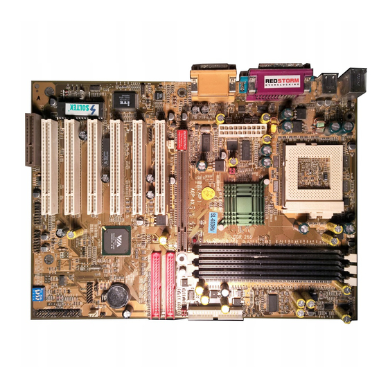
Page 12: Mainboard Layout
65DRV 1-2 MAINBOARD LAYOUT --- 65DRV FAN1 VT8633 Clock Generator AGP PRO 4X LED1 JDIMM1 JDIMM2 PCI 1 IDE1 FAN2 AC'97 IDE2 Codec PCI 2 JCD_IN1 PCI 3 LPC I/O Controller Battery VT8233 PCI 4 JBAT1 PCI 5 SCR1 WOL1 PCI 6 CNR 1 USB2... -
Page 13: Chipset Diagram
Introduction 1-3 CHIPSET DIAGRAM--- 65DRV Socket 370 3D Graphics Main AGP PRO Slot Controller VT8633 Memory (DDR DRAM) AC'97 Codec USBx6 Keyboard & Mouse LPC lO ATA 33/66/100 VT8233 Serial Port x 2 Infrared Port x 1 PM Control, Parallel Port x 1 FDD x1 GPIO, Reset Hardware Monitoring... - Page 14 65DRV MEMO MEMO...
-
Page 15: Chapter 2 Hardware Setup
Hardware Setup CHAPTER HARDWARE SETUP ATTENTION !!! 1. Please refer to your processor installation or other documentation attached with your CPU for more de- tailed installing instruction. 2. Installing a heat sink and cooling fan is necessary for proper heat dissipation from your CPU. Incorrect in- stallation may result in overheating and damage of your CPU. -
Page 16: Cpu Installation
65DRV 2-1 CPU INSTALLATION WARNING !!! • Make sure that +5V DCV and +3.3 DCV of your power supply are suitable for the processor. • Any attempt to operate the PIII or Celeron processor without a suitable cooling Fan will damage processor and other component. Pull out the lever from the socket, and then raise the lever up to a 90-degree angle. -
Page 17: Memory Installation
Hardware Setup 2-2 MEMORY INSTALLATION WARNING!!! • Make sure to unplug your power supply before adding or removing memory modules or other system components. Failure to do so may cause severe damage to both your mainboard and expansion cards. • Be careful when inserting or removing DIMM. Forcing a DIMM in or out of a socket improperly may damage the memory module or the socket. - Page 18 65DRV FAN1 VT8633 Clock Generator AGP PRO 4X LED1 JDIMM1 JDIMM2 PCI 1 IDE1 FAN2 AC'97 IDE2 Codec PCI 2 JCD_IN1 PCI 3 N O T I C E : W h e n L E D LPC I/O Controller Battery VT8233 “LED1”...
-
Page 19: Accelerated Graphics Port(Agp) Pro Installation
Hardware Setup 2-3 ACCELERATED GRAPHICS PORT(AGP) PRO INSTALLATION • The AGP Pro connector is an extension of the existing AGP connector and it is compatible with existing AGP cards. AGP Accelerator AGP Pro slot blockader Accelerated Graphics Port (AGP) Pro Slot 20-pin bay Rib(inside slot) 28-pin bay Rib(inside slot) -
Page 20: Hdd/Fdd Installation
65DRV 2-4 HDD/FDD INSTALLATION • To install HDD (Hard Disk Drive), you may connect the cable’s blue con- nector to the mainboard’s primary (IDE1) or secondary (IDE2) connector, and then connect the gray connector to your slave device and the black connector to your master device. - Page 21 Hardware Setup • To install FDD (Floppy Disk Drive), you may connect the end with single connector to the board , and connect the other end with two plugs to the floppy drives. FAN1 VT8633 Clock Generator AGP PRO 4X LED1 JDIMM1 JDIMM2...
-
Page 22: Fsb Frequency Select (By Sw1 Dip1~Dip4)
65DRV 2-5 FSB Frequency SELECT (By SW1 DIP1~DIP4) • Over clocking is not recommended, your system may work unstable. • SW1 DIP1~4 settings for FSB (Front Side Bus) Frequency Select is a redundancy device designed for professional CPU overclocking only. Since this mainboard is designed with CPU clock auto-detection function, you are recommended to use the SW1 DIP1~4 default setting for a stable system performance. -
Page 23: Jumper Setting For Devices On Board
Hardware Setup 2-6 JUMPER SETTING FOR DEVICES ON BOARD • The following diagrams show the locations of jumper blocks on the mainboard. CAUTION • Do not remove the jumper when power is on. Always make sure the power is off before changing any jumpers. Otherwise, mainboard could be damaged. -
Page 24: 2-6.2 Jdimm1/Jdimm2 Memory Module Voltage Select
65DRV 2-6.2 JDIMM1/JDIMM2 Memory Module Voltage Select This function allows you to select the voltage supplied to the DRAM. The default voltage (2.5V) should be used unless processor overclocking requires a higher voltage. FAN1 VT8633 J D I M M 1 / J D I M M 2 To S e l e c t Memory Module Voltage: Clock Generator... -
Page 25: 2-6.3 Jbat1 For Clear Cmos Data
Hardware Setup 2-6.3 JBAT1 For Clear CMOS DATA A battery should be used to supply the power for the CMOS RAM to retain the mainboard configuration. FAN1 VT8633 Clock Generator AGP PRO 4X LED1 JDIMM1 JDIMM2 PCI 1 IDE1 FAN2 JBAT1 To Clear CMOS DATA: AC'97 IDE2... -
Page 26: Connectors Configurations
65DRV 2-7 CONNECTORS CONFIGURATIONS • This section list out all connectors configurations for users’ reference. 2-7.1 FAN1, FAN2, FAN3 On board FAN Connector +12V SENSOR FAN1 On Board FAN Connector (FAN1): VT8633 On Board FAN Connector (FAN2): Clock Generator AGP PRO 4X LED1 JDIMM1 JDIMM2... -
Page 27: 2-7.2 Wol1 Wake-On-Lan Connector
Hardware Setup 2-7.2 WOL1 Wake-On-LAN Connector FAN1 +5V standby VT8633 Clock Generator AGP PRO 4X LED1 JDIMM1 JDIMM2 PCI 1 IDE1 FAN2 AC'97 IDE2 Codec Wake On LAN: PCI 2 JCD_IN1 PCI 3 LPC I/O Controller Battery VT8233 PCI 4 Connect the Wake JBAT1 On LAN signal from... -
Page 28: 2-7.3 Jcd_In1 Cd-Rom Audio Connector
65DRV 2-7.3 JCD_IN1 CD-ROM Audio Connector FAN1 JCD_IN1 CD-ROM Audio Connector: VT8633 JCD_IN1 PIN NO. Clock Generator AGP PRO 4X LED1 PIN 1 JDIMM1 JDIMM2 PCI 1 IDE1 FAN2 AC'97 IDE2 Codec Left PCI 2 JCD_IN1 PIN 2 Channel PCI 3 LPC I/O Controller Battery... -
Page 29: 2-7.4 Rt2 Thermal Sensor Connector
Hardware Setup 2-7.4 RT2 Thermal Sensor Connector FAN1 Thermal Sensor Connector (RT2): VT8633 Clock Generator AGP PRO 4X LED1 JDIMM1 JDIMM2 PCI 1 IDE1 FAN2 AC'97 IDE2 Codec PCI 2 JCD_IN1 PCI 3 LPC I/O Controller Battery VT8233 PCI 4 JBAT1 PCI 5 SCR1... -
Page 30: 2-7.5 Complex Header Con1
65DRV 2-7.5 Complex Header CON1 • This complex Header consists of 9 connectors providing various supports: CON1 15 15 SUSPEND LED SMI SIGNAL SUSPEND LED SIGNAL POWER SWITCH ATX POWER SWITCH NO CONNECTION NO CONNECTION NO CONNECTION POWER LED NO CONNECTION NO CONNECTION INFRARED(IR) INFRARED TRANSMIT SIGNAL... - Page 31 Hardware Setup 6. Power LED Connector: CONNECTION: Connected to System Power LED. FUNCTION: To supply power to “System Power LED”. 7. Reset Switch Connector: CONNECTION: Connected to the case-mounted “Reset Switch”. FUNCTION: To supply power to “Reset Switch” and support system re- boot function.
-
Page 32: 2-7.6 Atx Power Supply Connector
65DRV 2-7.6 ATX Power Supply Connector • This connector connects to an ATX power supply. The plug from the power supply should only be inserted to ATX Power connector in a specific orientation. Find the proper orientation and push it down firmly to make sure that all pins are aligned. -
Page 33: 2-7.7 Chassis Panel Connectors
Hardware Setup 2-7.7 Chassis Panel Connectors A : PS/2 MOUSE PORT B : USB O PORT C : LPT 1 PORT D : GAME/MIDI PORT E : PS/2 KEYBOARD PORT F : USB 1 PORT G : COM 1 PORT H : LINE OUT/SPEAKER OUT PORT : LINE IN J : MICROPHONE... -
Page 34: 2-7.8 Scr1 Smart Card Reader Connector
65DRV 2-7.8 SCR1 Smart Card Reader Connector • The connector “SCR1” allows you to use Smart Card Reader. It compli- ant with Personal Computer Smart Card (PC/SC) working group stand- ard and smart card (ISO 7816) protocols. FAN1 VT8633 Clock Generator AGP PRO 4X LED1... -
Page 35: 2-7.9 Cnr Communication And Networking Riser Slot
Hardware Setup 2-7.9 CNR Communication And Networking Riser Slot • This connector allows you to use network, modem or audio riser cards. FAN1 VT8633 Clock Generator AGP PRO 4X LED1 JDIMM1 JDIMM2 PCI 1 IDE1 FAN2 AC'97 IDE2 Codec PCI 2 JCD_IN1 PCI 3 LPC I/O... -
Page 36: 2-7.10 Usb Header (Usb2 & Usb3 Header)
65DRV 2-7.10 USB Header (USB2 & USB3 Header) • This header is for connecting the additional USB cable to provides you additional two USB ports. User can order the additional USB cable from your mainboard dealer and vender. Additional USB Cable (Optional) Black Black Green... - Page 37 Hardware Setup MEMO MEMO...
-
Page 38: Chapter 3 Software Setup
65DRV CHAPTER SOFTWARE SETUP ABOUT SUPPORT CD • In Support CD, it contains most informations for user’s requirement, such as Acrobat Reader, BIOS, User’s full version Manual, Driver, Hardware Monitor (if mainboard supports this function), Patch, and Utilities etc.,. User can browse the CD and get further details in regard of our mainboard. -
Page 39: Via Chipset Driver Installation (4-In-1 Driver)
Software Setup 3-1 VIA CHIPSET DRIVER INSTALLATION (4-IN-1 DRIVER) • Please put the Support CD • When a welcome window provided in your mainboard appears on the screen, us- package into the CD-ROM ers should choose “Install drive. Driver”. • Click on the “VIA Chipset •... - Page 40 65DRV • Press select the checkbox as below: Bus Master PCI IDE Driver AGP VxD Driver VIA Chipset Function’s Registry IRQ Routing Miniport Driver Next Note: For user who is upgrading VIA Drivers, we recommend to install the 4-in-1 as it will automatically detect and update the necessary drivers. •...
- Page 41 Software Setup • Select “Install VIA AGP Next VxD” in turbo mode and press Next button to co- ntinue. • Select “Install VIA IRQ Next Routing Miniport Driver” checkbox, then click the “Next” button to continue. • After all these setup proce- Finish dures have finished, please restart your computer by...
-
Page 42: Hardware Monitor Installation
65DRV 3-2 HARDWARE MONITOR INSTALLATION • Please put the Support CD • When a welcome window provided in your mainboard appears on the screen, us- package into the CD-ROM ers should choose “Install drive. Driver”. • Click on the “Hardware •... - Page 43 Software Setup • Click on the “OK” button. This screen shows the ITE SMARTGUARDIAM. It shows the i n f o r m a t i o n a b o u t s y s t e m temperatures, voltages and Fan speed.
-
Page 44: Ac'97 Audio Codec Driver Installation
65DRV 3-3 AC’97 AUDIO CODEC DRIVER INSTALLATION • Please put the Support CD • When a welcome window provided in your mainboard appears on the screen, us- package into the CD-ROM ers should choose “Install drive. Driver”. • Click on the “VIA Chipset •... - Page 45 Software Setup MEMO MEMO...
-
Page 46: Chapter 4 Bios Setup
65DRV CHAPTER BIOS SETUP THE BIOS • BIOS stands for Basic Input and Output System. It is sometimes called ROM BIOS because it is stored in a Read-Only Memory(ROM) chip on the mainboard. BIOS is the first program to run when you turn on your computer. -
Page 47: What Is Bios Setup
BIOS Setup 4-1 WHAT IS BIOS SETUP • BIOS setup is an interactive BIOS program that you need to run when: 1. Changing the hardware of your system. (For example: installing a new Hard Disk etc.) 2. Modifying the behavior of your computer. (For example: changing the system time or date, or turning special features on or off etc.) 3. -
Page 48: 4-5.1 Before Upgrading Bios
65DRV • The upgrade utility can be loaded on a floppy diskette and used to provide the capability to save, verify, and update the system BIOS. The upgrade utility can be run from a hard disk drive or a network drive. 4-5.1 BEFORE UPGRADING BIOS •... - Page 49 BIOS Setup Step 4. Type awdflash *.bin /sn/py/cc and then press <Enter> to run BIOS upgrade program. (*.bin depends on your mainboard model and version code. Instead of typing “*”, you should type specific file name for your specific mainboard). Step 5.
- Page 50 65DRV Award Flash Memory Writer Start Screen Award Flash Memory Writer Complete Screen...
- Page 51 BIOS Setup The parameters of AWDFLASH.EXE /sn: No original BIOS backup /py: Program flash memory /cc: Clear CMOS data (and update data automatically) after pro- gramming NOTE: Users can type AWDFLASH /? to get further details about the parameters. Incorrect usage of the parameter will damage the BIOS information, so we strongly recommend user to leave parameters alone unless you fully understand their function.
-
Page 52: Bios Setup
65DRV 4-6 BIOS SETUP --- CMOS SETUP UTILITY 4-6.1 CMOS SETUP UTILITY • This mainboard comes with the AWARD BIOS from AWARD Software Inc. Enter the CMOS Setup Utility Main Menu by: 1. Turn on or reboot your system. After a series of diagnostic checks, the following message will appear: PRESS <DEL>... -
Page 53: 4-6.2 Standard Cmos Setup
BIOS Setup 4-6.2 STANDARD CMOS SETUP • Standard CMOS Setup records some basic system hardware configuration and sets the system clock and error handling. You only need to modify the configuration values of this option if you want to change your system hard- ware configuration or when the data stored in the CMOS memory gets lost or damaged. - Page 54 65DRV Date (mm:dd:yy) The BIOS determines the day of the week from the other date information. This field is for information only. Press the left or right arrow key to move to the desired field (date, month, year). Press the PgUp or PgDn key to increment the setting, or type the desired value into the field.
- Page 55 BIOS Setup Drive A / Drive B Select this field to the type(s) of floppy disk drive(s) installed in your system. The choices are: 360KB, 5.25in; 1.2MB, 5.25in; 720KB, 3.5in; 1.44MB, 3.5in; 2.88MB, 3.5in; None. Video Select the type of primary video subsystem in your computer.
-
Page 56: 4-6.3 Advanced Bios Features
65DRV 4-6.3 ADVANCED BIOS FEATURES • ADVANCED BIOS FEATURES improves your system performance or sets up system features according to your preference. Run the ADVANCED BIOS FEATURES as follows: 1. Choose “ADVANCED BIOS FEATURES” from the Main Menu and a screen with a list of options will appear: CMOS Setup Utility - Copyright (C) 1984-2001 Award Software Advanced BIOS Features... - Page 57 BIOS Setup 2. Use one of the arrow keys to move between options and modify the selected options by using PgUp / PgDn / + / - keys. An explanation of the <F> keys follows: <F1>: “Help” gives options available for each item. <F5>: Get the previous values.
- Page 58 65DRV CPU L2 Cache ECC When you select Enabled, it will speed up memory Checking checking when the external cache contains ECC SRAMs. The choices: Enabled; Disabled. Processor Number Choose Disabled or Enabled. When enabled, the Feature processor serial number will display during the boot up screen.
- Page 59 BIOS Setup Gate A20 Option Gate A20 refers to the way the system addresses memory above 1 MB (extended memory). When set to Fast, the system chipset controls Gate A20. When set to Normal, a pin in the keyboard control- ler controls Gate A20.
-
Page 60: 4-6.4 Advanced Chipset Features
65DRV 4-6.4 ADVANCED CHIPSET FEATURES • ADVANCED CHIPSET FEATURES is used to modify the values of chipset buffers. These buffers control the system options. Run the ADVANCED CHIPSET FEATURES as follows: 1. Choose “ADVANCED CHIPSET FEATURES” from the Main Menu and a list of option will appear: CMOS Setup Utility - Copyright (C) 1984-2001 Award Software Advanced Chipset Features... - Page 61 BIOS Setup DRAM CLOCK/DRIVE CONTROL • When this option is chosen, the following item appears for user’s configuration. CMOS Setup Utility - Copyright (C) 1984-2001 Award Software DRAM Clock/Drive Control Item Help Current FSB Frequency Menu Level DRAM Clock By SPD DRAM Timing By SPD SDRAM Cycle Length...
- Page 62 65DRV * Bank Interleave The choices: Disabled; 2 Bank; 4 Bank. The choices: Disabled; 2 Bank; 4 Bank. * DRAM Command Rate AGP & P2P BRIDGE CONTROL • When this option is chosen, the following item appears for user’s configuration. CMOS Setup Utility - Copyright (C) 1984-2001 Award Software AGP &...
- Page 63 BIOS Setup * AGP Driving Control This item allows you to adjust the AGP driving force. Choose Manual to key in a AGP Driving Value in the next selection. This field is recommended to set in Auto for avoiding any error in your system. The choices: Manual;...
- Page 64 65DRV CPU & PCI BUS CONTROL • When this option is chosen, the following item appears for user’s configuration. CMOS Setup Utility - Copyright (C) 1984-2001 Award Software CPU & PCI Bus Control Item Help Enabled CPU to PCI Write Buffer Menu Level Enabled PCI Master 0 WS Write...
- Page 65 BIOS Setup Memory Hole In order to improve performance, certain space in memory is reserved for ISA cards. This memory must be mapped into the memory space below 16MB. The choices: 15M-16M; Disabled. System BIOS Selecting Enabled allows caching of the system Cacheable BIOS ROM at F0000h-FFFFFh, resulting in better system performance.
-
Page 66: 4-6.5 Integrated Peripherals
65DRV 4-6.5 INTEGRATED PERIPHERALS • INTEGRATED PERIPHERALS option allows you to get some information inside your system when it is working. Run the INTEGRATED PERIPHERALS as follows: 1. Choose “INTEGRATED PERIPHERALS” from the Main Menu and a list of options will appear: CMOS Setup Utility - Copyright (C) 1984-2001 Award Software Integrated Peripherals Item Help... -
Page 67: Via Onchip Ide Device
BIOS Setup VIA ONCHIP IDE DEVICE • When this option is chosen, the following item appears for user’s configuration. CMOS Setup Utility - Copyright (C) 1984-2001 Award Software VIA OnChip IDE Device Item Help OnChip IDE Channel0 Enabled OnChip IDE Channel1 Enabled Menu Level IDE Prefetch Mode... -
Page 68: Via Onchip Pci Device
65DRV * Primary Choose Auto or Mode 0~4. The BIOS will detect the Master / Slave PIO HDD mode type automatically when you choose Secondary Auto. You need to set to a lower mode than Auto Master / Slave PIO when your hard disk becomes unstable. - Page 69 BIOS Setup * VIA-3068 MC97 This option allows you to decide to enable/disable Modem the Onchip Modem. The choices: Auto; Disabled. VIA SUPERIO DEVICE • When this option is chosen, the following item appears for user’s configuration. CMOS Setup Utility - Copyright (C) 1984-2001 Award Software VIA SuperIO Device Item Help Onboard FDC Controller...
- Page 70 65DRV * Onboard Serial Select a logical COM port name and matching Port 1 / Port 2 address for the first and second serial ports. Select an address and corresponding interrupt for the first and second serial ports. * UART Mode Select The second serial port on your system may offer a variety of infrared port modes.
- Page 71 BIOS Setup * MIDI Port IRQ This item allows you to select the MIDI Port IRQ. The choices: 5, 10 Init Display First Initialize the AGP video display before initializing any other display device on the system. Thus the AGP display becomes the primary display.
-
Page 72: 4-6.6 Power Management Setup
65DRV 4-6.6 POWER MANAGEMENT SETUP • POWER MANAGEMENT SETUP allows you to set the system’s power saving functions. Run the POWER MANAGEMENT SETUP as follows: 1. Choose “POWER MANAGEMENT SETUP” from the Main Menu and a list of options will appear: CMOS Setup Utility - Copyright (C) 1984-2001 Award Software Power Management Setup Item Help... - Page 73 BIOS Setup ACPI Function Select Enabled only if your computer’s operating system supports the Advanced Configuration and Power Interface (ACPI) specification. Currently, Windows NT 5.0 supports ACPI. ACPI Suspend Type This item allows you to select the ACPI suspend type. You can select S3(STR) for suspending to DRAM or S1(POS) for power on suspend under Windows 98 ACPI mode.
- Page 74 65DRV Always On Monitor will remain on during power saving modes. Monitor blanked when the systems enters the Suspend Suspend --> Off mode. Monitor blanked when the system enters either Suspend or All Modes --> Off Standby modes. Video Off Method This determines the manner by which the monitor is blanked.
- Page 75 BIOS Setup IRQ/EVENT ACTIVITY DETECT • When this option is chosen, the following item appears for user’s configuration. CMOS Setup Utility - Copyright (C) 1984-2001 Award Software IRQ/Event Activity Detect Item Help LPT/COM Menu Level LPT & COM HDD & FDD PCI Master Disabled PowerOn by PCI Card...
- Page 76 65DRV * PowerOn by PCI Card This item allows system wake up by PCI Device. * Modem Ring Resume An input signal on the serial Ring Indicator (RI) Line (in other words, an incoming call on the modem) Awakens the system from a soft off state. * RTC Alarm Resume When Enabled, you can set the data and time at which the RTC (Real Time Clock) alarm awakens the system from suspend mode.
- Page 77 BIOS Setup * IRQ ACTIVITY MONITORING • When this option is chosen, the following item appears for user’s configuration. CMOS Setup Utility - Copyright (C) 1984-2001 Award Software IRQ Activity Monitoring Primary INTR Item Help IRQ-3 (COM2) Enabled Menu Level IRQ-4 (COM1) Enabled IRQ-5 (LPT2)
-
Page 78: 4-6.7 Pnp / Pci Configuration
65DRV 4-6.7 PNP / PCI CONFIGURATION • PNP/PCI CONFIGURATION allows you to modify the system’s power saving functions. Run the PNP/PCI CONFIGURATION as follows: 1. Choose “PNP/PCI CONFIGURATION” from the Main Menu and a screen with a list of options will appear: CMOS Setup Utility - Copyright (C) 1984-2001 Award Software PnP/PCI Configurations Item Help... - Page 79 BIOS Setup PNP OS Installed Select Yes if the system operating environment is Plug-and-Play aware (e.g., Windows95). NOTE: BIOS will automatically disable all PnP resources except the boot device card when you select Yes on Non-PnP operating system. Reset Configuration Normally, you leave this Disabled.
- Page 80 65DRV PCI/VGA Palette Snoop This option allows the BIOS to preview VGA status, and to modify the information delivered from the feature Connector of the VGA card to MPEG card. This option can solve the display inversion to black after you have used MPEG card. Assign IRQ for VGA Select Enabled if you system has a VGA controller and you have one or more VGA devices connected.
-
Page 81: 4-6.8 Pc Health Status
BIOS Setup 4-6.8 PC HEALTH STATUS • This section helps you to get more information about your system including CPU temperature, FAN speed and voltage. It is recommended that you contact your mainboard supplier to get proper values about the setting of the CPU temperature. Run the “SMARTDOC ANTI-BURN SHIELD”... - Page 82 65DRV Shutdown Tempera- This feature prevents your CPU from damage by ture over heat. If the CPU’s temperature is higher than “CPU warning temperature” that you select in this field, the BIOS will shut down your system within 3 seconds. CPU Vcore Shows CPU core actual voltage value.
-
Page 83: 4-6.9 Frequency/Voltage Control
BIOS Setup 4-6.9 FREQUENCY/VOLTAGE CONTROL Run the “FREQUENCY/VOLTAGE CONTROL” as following: 1. Choose “FREQUENCY/VOLTAGE CONTROL” from the Main Menu and a screen with a list of options will appear: CMOS Setup Utility - Copyright (C) 1984-2001 Award Software Frequency Control Item Help CPU Vcore Select Default... - Page 84 65DRV CPU Vcore This item allows you to adjust the CPU core Voltage. Select Using higher CPU core Voltage may help, when overclocking but may in shortening of your processor’s lite. It is strongly recommended that you leave this item at default. To reduce the occurrence of electromagnetic inter- Auto Detect DIMM/PCI CLK...
-
Page 85: 4-6.10 Load Optimized Defaults
BIOS Setup 4-6.10 LOAD OPTIMIZED DEFAULTS • When you press <Enter> on this item, you will get a confirmation dialog box with a message similar to: “ Load Optimized Defaults (Y / N) ? N ” “Y” is for “Yes”, and “N” is for “No”. Pressing “Y”... -
Page 86: 4-6.12 Save & Exit Setup
65DRV 7. Move the cursor to Save & Exit Setup to save the option you have just configured; otherwise the old password will still be there the next time you turn your system on. 8. Press <Enter> to exit to the Main Menu. NOTE: If you forget or lose the password, the only way to access the system is to clear the CMOS RAM. - Page 87 BIOS Setup MEMO MEMO...
-
Page 88: Appendices
65DRV APPENDICES This chapter contains the following topics : APPENDIX-1 TECHNICAL TERMS INTRODUCTION APPENDIX-2 IDENTIFYING BIOS VERSION/ BIOS PART NUMBER APPENDIX-3 IDENTIFYING MAINBOARD MODEL NUMBER... -
Page 89: Appendix-1 Technical Terms Introduction
APPENDICES APPENDIX-1 TECHNICAL TERMS INTRODUCTION Technical Terms Introduction Tech Term Meaning Accelerated Graphic Port Audio Modem Riser Advanced Communication Riser Central Processing Unit CMOS Complementary Metal Oxide Semiconductor CRIMM Continuity RIMM Communication and Networking Riser Direct Memory Access Desktop Management Interface DIMM Dual Inline Memory Module DRAM... -
Page 90: Number
65DRV APPENDIX-2 IDENTIFYING BIOS VERSION AND BIOS PART NUMBER • When you boot up your computer, you may see a screen which tells your computer is phoenixnet™ enabled. Please see Picture-1 below for an illustration. • When the screen shows up press “Tab” key for BIOS information. Picture-1... - Page 91 APPENDICES • See Picture-2 below for BIOS version and BIOS part number identification. Picture-2 BIOS VERSION example: REV T2.1 BIOS ID STRING example: 6A69RSNCC...
-
Page 92: Appendix-3 Identifying Mainboard Model Number
65DRV APPENDIX-3 IDENTIFYING MAINBOARD MODEL NUMBER • Usually the mainboard model number is labeled on the side of ISA slot or PCI slot, please see the picture shown below for an illustration. MAINBOARD MODEL NUMBER example: SL-65KV2 MAINBOARD SERIAL NUMBER example: 0012000T005679... - Page 93 APPENDICES MEMO MEMO...
Need help?
Do you have a question about the SL-65DRV and is the answer not in the manual?
Questions and answers