Table of Contents
Advertisement
Advertisement
Table of Contents

Subscribe to Our Youtube Channel
Related Manuals for SOLTEK SL-75KV


Summary of Contents for SOLTEK SL-75KV
- Page 1 T h e S o u l C o m p u t e r T e c h n o l o g y...
- Page 2 In no event shall Soltek computer inc. Be li- able for any loss or profits, loss of business, loss of use or data, interruption of business, or for indirect, special, incidental, or con- sequential damages of any kind, even if Soltek computer inc.
-
Page 3: Soltek Computer Inc
SOLTEK AROUND THE WORLD SOLTEK COMPUTER INC. Address : 7F, No. 306-3, Ta-Tung Rd, Sec.1, Hsi-Chin, Taipei- Hsien, Taiwan, R.O.C. Telephone : 886-2-2642-9060 : 886-2-2642-9065 E-mail : sashia@soltek.com.tw Web site : http://www.soltek.com.tw SOLTEK KOREA INC. Address : 1002, Chungjin Bldg. 53-5 Wonhyo-Ro, 3-Ka,... -
Page 4: Table Of Contents
75KV/75KV-X C O N T E N T Chapter 1 INTRODUCTION ............6 1-1 ITEM LIST CHECKUP ..............6 1-2 PROCESSOR ................6 1-3 CHIPSET ..................6 1-4 MEMORY ..................7 1-5 BIOS ..................... 7 1-6 MULTI-I/O FUNCTION ..............7 1-7 FORM FACTOR ................ - Page 5 75KV/75KV-X Chapter 3 SOFTWARE SETUP ........... 29 3-1 ABOUT SUPPORT CD ............... 29 3-2 HARDWARE MONITOR INSTALLATION ........29 3-3 VIA CHIPSET DRIVER INSTALLATION (4-IN-1 DRIVER) ..31 3-4 AC’97 AUDIO CODEC INSTALLATION ........35 Chapter 4 BIOS Setup ..............37 4-1 INTRODUCE THE BIOS .............
-
Page 6: Chapter 1 Introduction
75KV/75KV-X CHAPTER 1 INTRODUCTION 1-1 ITEM LIST CHECKUP • Motherboard • Support CD • User’s Manual • 2-In-1 Bonus Pack CD • 2-In-1 Bonus Pack Manual • Temperature Sensor Cable • ATA66 IDE Cable • RS232 Cable 1-2 PROCESSOR • Supports AMD Athlon Thunderbird 700MHz/ 750MHz/ 800MHz/ 850MHz/ 900MHz/ 950MHz/1.0GHz processors or higher. -
Page 7: Memory
75KV/75KV-X --- 100MHz DDR(Double Data Rate) transfer on Athlon CPU address and data buses. --- Supports full AGP v2.0 capability for maximum bus utilization including 1x, 2x, and 4x mode transfers. --- Both Windows 95 VxD and Windows 98 / Windows 2000 miniport driv- ers are supported for ineroperability with major AGP-based 3D and DVD- capable multimedia accelerators. -
Page 8: Form Factor
75KV/75KV-X 1-7 FORM FACTOR • ATX form factor, 4 layers PCB. • Motherboard size: 22.0cm x 30.5cm 1-8 AC’97 CODEC FUNCTION • Adopts onboard AC’97 Audio Codec controller chip. 1-9 MISCELLANOUS • PCI 2.2 compliant, 32-bit 3.3V PCI interface with 5V tolerant inputs. •... -
Page 9: 1-10.1 Motherboard Layout
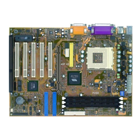
75KV/75KV-X 1-10.1 MOTHERBOARD LAYOUT --- 75KV • Default Setting: AMD Athlon Thunderbird 100MHz. FAN1 JP10 ATX POWER JP11 5 4 3 2 1 SOCKET A W210 KT-133 COM 2 4x AGP PRO IDE1 CD_IN2 PCI 1 CD_IN1 AC'97 IDE2 Codec PCI 2 USB1 PCI 3... -
Page 10: 1-10.2 Motherboard Layout
75KV/75KV-X 1-10.2 MOTHERBOARD LAYOUT --- 75KV-X • Default Setting: AMD Athlon Thunderbird 100MHz. FAN1 JP10 ATX POWER JP11 5 4 3 2 1 SOCKET A W210 KT-133 COM 2 4x AGP PRO IDE1 CD_IN2 PCI 1 CD_IN1 AC'97 IDE2 Codec PCI 2 USB1 PCI 3... -
Page 11: Chipset Diagram
75KV/75KV-X 1-11 CHIPSET DIAGRAM • The KT133 / VT8363 and VT82C686A chipset is a high performance, cost- effective and energy efficient system controllor for the implementation of AGP / PCI / ISA desktop personal computer system based on 64-bit Socket- A (AMD Athlon) processors. -
Page 12: Chapter 2 Hardware Setup
75KV/75KV-X CHAPTER 2 HARDWARE SETUP 2-1 CPU INSTALLATION 1. Pull the lever sideways away from the socket, and then raise the lever up to a 90-degree angle. 2. Take note of the red circle as below picture. While inserting the CPU into the socket, you can find out there is a definite pin orientation for CPU and socket. -
Page 13: Amd Socket A (Socket 462) Processor
75KV/75KV-X 3. Make sure that the CPU position in the socket tightly, and then put the lever down to complete the CPU installation. 2-2 AMD SOCKET A (SOCKET 462) PROCESSOR XXXXXXXXXXX XXXXXXXXXXX XXXXXXXXXXXX XXXXXXXXXXXX XXXXXXX XXXXXXX XXXXXXXXX XXXXXXXXX XXXXXXXXXXX XXXXXXXXXXX XXXX XXXX •... -
Page 14: Cpu Frequency
75KV/75KV-X 2-3 CPU FREQUENCY CPU CLOCK PCI CLOCK 100MHz 33.3MHz (default) 103MHz 34.3MHz 105MHz 35.0MHz 110MHz 36.7MHz 112MHz 37.3MHz 115MHz 38.3MHz 120MHz 40.0MHz 124MHz 31.0MHz 133.3MHz 33.3MHz 140MHz 35.0MHz 150MHz 37.5MHz Premature wearing of the processor may result when overclocking. Be sure that the DIMM you use can handle the specified SDRAM MHz or else bootup will not be possible. -
Page 15: Jumper Definitions
75KV/75KV-X 2-4 JUMPER DEFINITIONS • The figure below shows the location fo the motherboard’s jumper blocks. CAUTION • Do not move the jumper with the power on. Always trun off the power and unplug the power cord from the computer before changing the jumper. Otherwise, the motherboard could be damaged. - Page 16 75KV/75KV-X JP3: FACTORY TEST Only for factory test. JP4/JP5: VOICE DIAGNOSTIC LANGUAGE SELECT Chinese Language English Language (default) Japanese Language Spanish Language NOTE: The Voice Diagnosis Technology (JP4, JP5, and JP8) is only supported by 75KV-X motherboard. JP8: VD-TECH CONTROLLER CHIP Enabled (default) Disabled JP7: POWER LOST RESUME...
- Page 17 75KV/75KV-X JP10/JP11: VIO SELECT JP10 3.3V (default) JP11 JP10 3.4V JP11 JP10 3.5V JP11 JP10 3.6V JP11 VIO allows you to select the voltage supplied to the DRAM, chipset, AGP, PCI, and the CPU’s I/O buffer. The default voltage (3.3V) should be used unless processor overclocking requires a higher voltage.
- Page 18 75KV/75KV-X CD_IN1/CD_IN2: CD-ROM AUDIO CONNECTOR PIN NO. CD_IN1 CD_IN2 PIN 1 Left Channel Left Channel PIN 2 PIN 3 Right Channel PIN 4 Right Channel...
-
Page 19: Connectors
75KV/75KV-X 2-5 CONNECTORS • In this section we list all external connectors that user will use them. 2-5.1 J3 AND J4 1 2 3 4 5 6 7 8 9 10 11 12 13 14 15 HDD LED CONNECTOR PIN 1 PIN 2 HDD LED SIGNAL PIN 3... - Page 20 75KV/75KV-X 1 2 3 4 5 6 7 8 9 10 11 12 13 14 15 ATX POWER SWITCH PIN 12 ATX POWER SWITCH PIN 13 The system power is controlled by a momentary switch connected to this lead. Pressing the button once will switch the system between ON and SOFT OFF.
- Page 21 75KV/75KV-X 1 2 3 4 5 6 7 8 9 10 11 12 13 14 15 SPEAKER CONNECTOR PIN 1 SPEAKER SIGNAL PIN 2 NONE PIN 3 PIN 4 This SPEAKER connector connects to the case- mounted speaker. Two sources (LINE OUT and DESCRIPTION SPEAKER) allow you to hear system beeps and warnings.
- Page 22 75KV/75KV-X 1 2 3 4 5 6 7 8 9 10 11 12 13 14 15 SUSPEND LED PIN 14 SUSPEND LED SIGNAL PIN 15 DESCRIPTION Connect to Suspend indicator light. A1 : 1st HDD LED A2 : 2nd HDD LED B : INFRARED (IR) A1 A2 C : POWER SWITCH...
-
Page 23: 2-5.2 Chassis Panel Connector
75KV/75KV-X 2-5.2 CHASSIS PANEL CONNECTOR A : PS/2 MOUSE PORT B : USB O PORT C : LPT 1 PORT D : GAME/MIDI PORT E : PS/2 KEYBOARD PORT F : USB 1 PORT G : COM 1 PORT H : LINE OUT/SPEAK OUT PORT : LINE IN J : MICROPHONE... -
Page 24: 2-5.3 Atx Power Supply Connector
75KV/75KV-X 2-5.3 ATX POWER SUPPLY CONNECTOR • This connector connects to an ATX power supply. The plug from the power supply only inserts in an orientation because of the different hole sizes. Find the proper orientation and push down firmly making sure that all pins are aligned. -
Page 25: 2-5.4 Second Usb Connector
75KV/75KV-X 2-5.4 SECOND USB CONNECTOR • This motherboard provides 4 sets of USB port. Besides 2 sets of them can be connected directly by USB devices, the others are built-in onboard for user to extend the USB function. • NOTE: User can order the 2nd USB connector from your motherboard dealer and vendor only. -
Page 26: 2-5.5 Ps/2 Mouse And Ps/2 Keyboard
75KV/75KV-X 2-5.5 PS/2 MOUSE AND PS/2 KEYBOARD PIN 6 : None PIN 6 : None PIN 5 : Mouse Clock PIN 5 : Keyboard Clock PIN 4 : Vcc PIN 4 : Vcc PIN 3 : GND PIN 3 : GND PIN 2 : None PIN 2 : None PIN 1 : Mouse Data... -
Page 27: 2-5.6 Irq Description
75KV/75KV-X 2-5.6 IRQ DESCRIPTION Function Description Priority IRQ 0 System Timer IRQ 1 Keyboard Controller IRQ 2 Programmable Interrupt IRQ 3 Serial Port (COM 2) IRQ 4 Serial Port (COM 1) IRQ 5 IRQ 6 Floppy Disk Controller IRQ 7 Parallel Port (LPT1) IRQ 8 Real Time Clock (RTC) -
Page 28: Voice Diagnosis Technology For 75Kv-X
75KV/75KV-X 2-6 VOICE DIAGNOSIS TECHNOLOGY FOR 75KV-X • The Voice Diagnostic Function provides user an indispensable assistance on troublieshooting while assembling your computer components. If there is any conflict or other latent problem triggers a boot-up failure, this new VD-TECH technology will voice you relistically where the conflict/problem is, then user can remove the malfunction quickly. -
Page 29: Chapter 3 Software Setup
75KV/75KV-X CHAPTER 3 SOFTWARE SETUP 3-1 ABOUT SUPPORT CD • In support CD, it contains most informations for user’s requirement, such as Acrobat Reader, BIOS, User’s full version Manual, Driver, Hardware Monitor(if motherboard supports this function), Patch, and Utilities etc,. User can browse the CD and get further details in regard of our motherboard. - Page 30 75KV/75KV-X Step 3: • Click on the “Hardware Monitor Utility”. Step 4: • Press Next button to continue. Step 5: • The default destination is C:\VIAhm, then press Next button to continue. Step 6: • Press Next button to finish the Hardware Monitor setup process.
-
Page 31: Via Chipset Driver Installation (4-In-1 Driver)
75KV/75KV-X 3-3 VIA CHIPSET DRIVER INSTALLATION (4-IN-1 DRIVER) Step 1: • Please put the support CD attached to motherboard into the CD-ROM drive. • When appears a welcome window as left screen, then user should choose “Install Driver” Step 2: •... - Page 32 75KV/75KV-X Step 5: • Press Next button to continue. Step 6: • Click “Yes” to continue. Step 7: • Press select the checkbox as below: Bus Master PCI IDE Driver AGP VxD Driver VIA Chipset Function’s Registry IRQ Routing Miniport Driver NOTE: In Windows 95/98, user doesn’t need to add “VIA Chipset Function’s Registry”...
- Page 33 75KV/75KV-X Step 9: • We recommend user to leave “Enable/ Disable [Ultra] DMA” checkbox empty. NOTE: Whether select this item or not, user needs to enable the Hard Disk DMA function in Control Panel manually. (For further details, please refer to next page) Step 10: •...
- Page 34 75KV/75KV-X Step 13: • After all the setup process is finished, please restart your computer by clicking on Finish. bout Hard Disk DMA Function Last but not least, user must enable the Hard Disk DMA function. The process is below: 1.
-
Page 35: Ac'97 Audio Codec Installation
75KV/75KV-X 3-4 AC’97 AUDIO CODEC INSTALLATION Step 1: • Please put the support CD attached to motherboard into the CD-ROM drive. • When appears a welcome window as left screen, then user should choose “Install Driver” Step 2: • Click on the “VIA Chipset Driver”. Step 3: •... - Page 36 75KV/75KV-X Step 5: • When asking you install or remove the audio driver, please select “Install” and press Next button to continue. Step 6: • It’s recommended for user to restart the computer after the audio driver is finished. Please select “Yes, I want to restart my computer now”.
-
Page 37: Chapter 4 Bios Setup
75KV/75KV-X CHAPTER 4 BIOS SETUP 4-1 INTRODUCE THE BIOS • BIOS stands for Basic Input Output System. It is sometimes called ROM BIOS because it is stored in a Read-Only Memory(ROM) chip on the motherboard. BIOS is the first program to run when you turn on your computer. -
Page 38: What Is Post
75KV/75KV-X lected and configures your computer accordingly. If the battery charge runs too low, the CMOS content will be lost and POST will issue a “CMOS in- valid” or “CMOS checksum invalid” message. If this happens, you may have to replace the battery. After the battery is replaced, the proper set- tings will need to be stored in SETUP. - Page 39 75KV/75KV-X Create a Boot Floppy (using a DOS system to create the bootable floppy) • Place an unformatted floppy diskette in the floppy drive and format the floppy using the /S option. Example: format a: /s • Alternatively, place a formatted floppy in the floppy drive and use the “sys” command.
- Page 40 75KV/75KV-X • Then appears a program window as below: • After upgraded, the system will reboot itself automatically. • NOTE: You will see a message “CMOS checksum error - Default loaded” during booting the system. Please press <Del> to run BIOS program, then reload “LOAD SETUP DEFAULTS”...
-
Page 41: Cmos Setup Utility
75KV/75KV-X 4-7 CMOS SETUP UTILITY • This VIA KT-133 motherboard comes with the AWARD BIOS from AWARD Software Inc. Enter the Award BIOS program Main Menu by: 1. Turn on or reboot your system. After a series of diagnostic checks, the following message will appear: PRESS <DEL>... -
Page 42: Standard Cmos Setup
75KV/75KV-X 4-8 STANDARD CMOS SETUP • Standard CMOS Setup allows you to record some basic system hardware configuration and set the system clock and error handling. You only need to modify the configuration values of this option when you change your system hardware configuration or the configuration stored in the CMOS memory gets lost or damaged. - Page 43 75KV/75KV-X Date (mm:dd:yy) Set the current date and time. Time (hh:mm:ss) Primary / Secondary This field records the specifications for all non-SCSI Master / Slave hard disk drives installed in your system. Refer to the respective documentation on how to install the drives. Drive A / Drive B Set this field to the type(s) of floppy disk drive(s) in- stalled in your system.
-
Page 44: Advanced Bios Features
75KV/75KV-X 4-9 ADVANCED BIOS FEATURES • ADVANCED BIOS FEATURS allows you to improve your system perfor- mance or set up sysem features according to your preference. Run the ADVANCED BIOS FEATURES as following: 1. Choose “ADVANCED BIOS FEATURES” from the Main Menu and a screen with a list of option will appear: 2. - Page 45 75KV/75KV-X CMOS Setup Utility - Copyright (C) 1984-2000 Award Software Advanced BIOS Features Virus Warning Disabled Item Help Menu Level CPU Internal Cache Enabled External Cache Enabled CPU L2 Cache ECC Checking Enabled Quick Power On Self Test Enabled First Boot Device Floppy Second Boot Device HDD-0...
- Page 46 75KV/75KV-X Virus Warning Enabled: Activates automatically when the system boots up causing a warning message to appear if there is anything attempting to access the boot sector or hard disk parti- tion table. Disabled: No warning message will appear when there is something attempting to access the boot sector or hard disk partition table.
- Page 47 75KV/75KV-X Boot Up NumLock Choose ON (default) or OFF. THis option lets user activates the NumLock function at boot-up. Status Gate A20 Option Choose Normal or Fast (default). This option allows the RAM to access the memory above 1MB by using the fast gate A20 line.
-
Page 48: Advanced Chipset Features
75KV/75KV-X 4-10 ADVANCED CHIPSET FEATURES • ADVANCED CHIPSET FEATURES allows you to change the values of chipset registers. These registers control the system options. Run the ADVANCED CHIPSET FEATURES as following: 1. Choose “ADVANCED CHIPSET FEATURES” from the Main Menu and a screen with a list of option will appear: 2. - Page 49 75KV/75KV-X CMOS Setup Utility - Copyright (C) 1984-2000 Award Software Advanced Chipset Features Item Help Bank 0/1 DRAM Timing SDRAM 8/10ns Menu Level Bank 2/3 DRAM Timing SDRAM 8/10ns Bank 4/5 DRAM Timing SDRAM 8/10ns SDRAM Cycle Length DRAM Clock Host CLK DRAM Drive Strength Auto...
- Page 50 75KV/75KV-X Bank 0/1 2/3 4/5 DRAM This item allows you to select the value in this field, Timing depending on whether the board has paged DRAMs or EDO (Extended Data Output) DRAMs. The choice: EDO 50ns, EDO 60ns, Slow, Medium, Fast, Turbo.
- Page 51 75KV/75KV-X System BIOS Choose Enabled or Disabled (default). When enabled, the access to the system BIOS ROM addressed at Cacheable F0000H - FFFFFH is cached. Video RAM Cacheable Choose Enabled or Disabled (default). When enabled, the access to the VGA RAM addressed is cached. AGP Aperture Size Choose 4, 8, 16, 32, 64 (default), 128 or 256 MB.
- Page 52 75KV/75KV-X OnChip Sound Enabled (default): Turn on AC’97 codec chip controller. Disabled: Turn off AC’97 codec chip controller or user can plug external add-on sound card. OnChip Modem Enabled: Turn on MC99 feature. Disabled (default): Turn off AC’97 codec chip control- ler or user can connect external add-on modem.
- Page 53 75KV/75KV-X Memory Parity/ECC This item enabled to detect the memory parity and Check Error Checking & Correcting. The choice: Enabled, Disabled. CPU Voltage Regulator This item allows user to adjust the CPU Vcore voltage. The instant damage of CPU is due to the wrong Vcore voltage setting, so that we recommend that user should leave this item with Default setting unless you know how to adjust it.
-
Page 54: Integrated Peripherals
75KV/75KV-X 4-11 INTEGRATED PERIPHERALS • INTEGRATED PERIPHERALS option allows you to get some informations inside your system when it is working. Run the INTEGRATED PERIPHERALS as following: 1. Choose “INTEGRATED PERIPHERALS” from the Main Menu and a screen with a list of option will appear: CMOS Setup Utility - Copyright (C) 1984-2000 Award Software Integrated Peripherals Item Help... - Page 55 75KV/75KV-X 2. Use one of the arrow keys to move between options and modify the se- lected options by using PgUp / PgDn / + / - keys. An explanation of the <F> keys follows: <F1>: “Help” gives oions available for each item. <Shift>...
- Page 56 75KV/75KV-X On-Chip Primary/ The chipset contains a PCI IDE interface with sup- Secondary PCI IDE port from two IDE channels. Select Enabled to acti- vate the first and/or the second IDE interface. Select Disabled to deactivate an interface if you install a pri- mary and/or second add-on IDE interface.
- Page 57 75KV/75KV-X Onboard FDC Select Enabled if your system has a floppy drive con- Controller troller (FDC) installed on the system board and you want to use it. If you install add-in FDC or the system has no floppy drive, select Disabled in this field. The choice: Enabled, Disabled.
- Page 58 75KV/75KV-X Parallel Port EPP Type Select EPP port type 1.7 or 1.9 The choice: EPP1.7, 1.9. Onboard Legacy Audio This field controls the onboard audio. • Sound Blaster • SB I/O Base Address • SB IRQ Select • SB DMA Select •...
-
Page 59: Power Management Setup
75KV/75KV-X 4-12 POWER MANAGEMENT SETUP • POWER MANAGEMENT SETUP allows you to set the system’s power saving functions. Run the POWER MANAGEMENT SETUP as following: 1. Choose “POWER MANAGEMENT SETUP” from the Main Menu and a screen with a list of option will appear: CMOS Setup Utility - Copyright (C) 1984-2000 Award Software Power Management Setup ACPI Function... - Page 60 75KV/75KV-X ACPI Function Enabled: Turn on ACPI function. Disabled (default): Turn off ACPI function. • Press <Enter> on the Power Management item, then there is a list of it appears for you to choose further setting. CMOS Setup Utility - Copyright (C) 1984-2000 Award Software Power Management Power Management User Define...
- Page 61 75KV/75KV-X ACPI Suspend Type This item will allow you to select the ACPI suspend type. You can select S3(STR) for suspending to DRAM or S1(POS) for power on suspend under Windows 98 ACPI mode. The choice: S1(POS), S3(STR). PM Control by APM When enabled, an Advanced Power Management device will be activated to enhance the Max.
- Page 62 75KV/75KV-X Soft-Off by PWRBTN Instant-Off (default): Turn off the system poer at once after pushing the power button. Delay 4 Sec: Turn off the system power 4 seconds after pushing the power button. (to meet PC97/98 spec) • Press <Enter> on the Wake Up Events item, then there is a list of it appears for you to choose further setting.
- Page 63 75KV/75KV-X Wake Up On LAN/Ring An input signal on the serial Ring Indicator (RI) line (in other words, an incoming call on the modem) awak- ens the system from a soft off state. The choice: Enabled, Disabled. RTC Alarm Resume When Enabled, you can set the data and time at the which the RTC (Real Time Clock) alarm awakens the system from suspend mode.
- Page 64 75KV/75KV-X The following is a list of IRQ’s (Interrupt ReQuests), which can be exempted much as the COM ports and LPT ports above can. When an I/O device wants to gain the attention of the operating system, it signals this by causing an IRQ to occur.
-
Page 65: Pnp / Pci Configuration
75KV/75KV-X 4-13 PNP / PCI CONFIGURATION • PNP/PCI CONFIGURATION allows you to set the system’s power saving functions. Run the PNP/PCI CONFIGURATION as following: 1. Choose “PNP/PCI CONFIGURATION” from the Main Menu and a screen with a list of option will appear: CMOS Setup Utility - Copyright (C) 1984-2000 Award Software PnP/PCI Configurations PNP OS Installed... - Page 66 75KV/75KV-X PNP OS Installed Yes: OS supports Plug and Play function. No (default): OS doesn’t support Plug and Play function. NOTE: BIOS will automatically disable all PnP resources except the boot device card when you select Yes on Non-PnP operating system. Choose Enabled or Disabled (default).
- Page 67 75KV/75KV-X DMA Resources Press Enter. Please refer to the below list. CMOS Setup Utility - Copyright (C) 1984-2000 Award Software DMA Resources DMA-0 assigned to PCI/ISA PnP Item Help DMA-1 assigned to PCI/ISA PnP Menu Level DMA-3 assigned to PCI/ISA PnP DMA-5 assigned to PCI/ISA PnP DMA-6 assigned to...
-
Page 68: Pc Health Status
75KV/75KV-X 4-14 PC HEALTH STATUS • This section helps you to get more information about your system including CPU temperature, FAN speed and voltage. It is recommended that you contact with your motherboard supplier to get proper value about your set- ting of the CPU temperature. -
Page 69: Frequency/Voltage Control
75KV/75KV-X 4-15 FREQUENCY/VOLTAGE CONTROL CMOS Setup Utility - Copyright (C) 1984-2000 Award Software Frequency Control Item Help Auto Detect DIMM/PCI Clk Enabled Spread Spectrum Modulated Disabled Menu Level CPU Host Clock (CPU/PCI) Default Method In Linear Funct. Increase CPU HOST By Linear Funct. :Move Enter:Select +/-/PU/PD:Value F10:Save ESC:Exit F1:General Help F5:Previous Values F6:Fail-Safe Defaults F7:Optimized Defaults Auto Detect... -
Page 70: Load Fail-Safe Defaults
75KV/75KV-X 4-16 LOAD FAIL-SAFE DEFAULTS • When you press <Enter> on this item you get a confirmation dialog box with a message similar to: “ L o a d F a i l - S a f e D e f a u l t s ( Y / N ) ? N ”... -
Page 71: Set Supervisor / User Password
75KV/75KV-X 4-18 SET SUPERVISOR / USER PASSWORD • These two options allow you to set your sysem passwords. Normally, the supervisor has a higher ability to change the CMOS setup option than the user. The way to set up the passwords for both Supervisor and User are as follows: 1. -
Page 72: Save & Exit Setup
75KV/75KV-X 4-19 SAVE & EXIT SETUP • SAVE & EXIT SETUP allows you to save all modifications you have speci- fied into the CMOS memory. Highlight this option on the Main Menu and the following message appears: “SAVE to CMOS and EXIT (Y/N) ? Y “...
Need help?
Do you have a question about the SL-75KV and is the answer not in the manual?
Questions and answers