Table of Contents
Advertisement
Quick Links
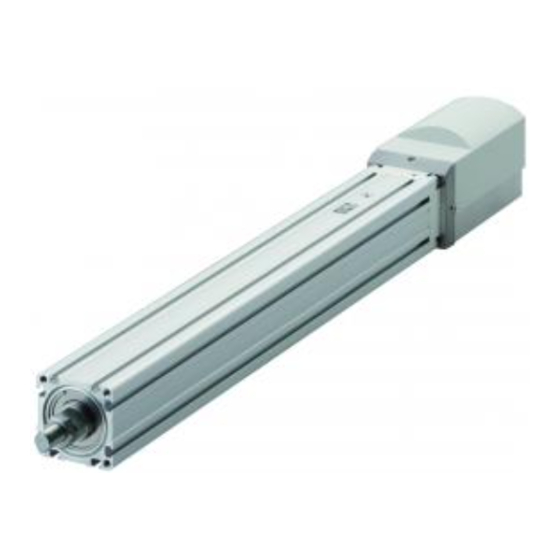
Electric Actuator
ERL2 Series (Slider Type)
ESD2 Series (Rod Type)
INSTRUCTION MANUAL
SM-612226-A/4
INSTRUCTION MANUAL
MSV-484083
• Read this Instruction Manual before using the product.
• Read the safety notes carefully.
• Keep this Instruction Manual in a safe and convenient place for future reference.
Advertisement
Table of Contents

Related Manuals for CKD ERL2 Series


Summary of Contents for CKD ERL2 Series
- Page 1 Electric Actuator ERL2 Series (Slider Type) ESD2 Series (Rod Type) INSTRUCTION MANUAL SM-612226-A/4 INSTRUCTION MANUAL MSV-484083 • Read this Instruction Manual before using the product. • Read the safety notes carefully. • Keep this Instruction Manual in a safe and convenient place for future reference.
-
Page 2: Preface
• Since there are a wide variety of customer applications, it is impossible for CKD to be aware of all of them. Depending on the application or usage, the product may not be able to exercise its full performance or an accident may occur due to fluid, piping, or other conditions. -
Page 3: Safety Information
SM-612226-A/4 SAFETY INFORMATION SAFETY INFORMATION When designing and manufacturing any device incorporating the product, the manufacturer has an obligation to ensure that the device is safe. To that end, make sure that the safety of the machine mechanism of the device and the electric system that controls such mechanism is ensured. In order to use our products safely, it is important to select, use, handle, and maintain the products properly. -
Page 4: Precautions On Product Use
SM-612226-A/4 SAFETY INFORMATION Precautions on Product Use DANGER Do not use the product for the following applications: • Medical equipment pertaining to sustainment and management of human life and body • Mechanism and mechanical device for transferring and transporting people •... -
Page 5: Table Of Contents
1.3.1 ERL2 Series (slider type) ................4 1.3.2 ESD2 Series (rod type) ................5 1.3.3 ERL2 Series (slider type) optional parts ............6 1.3.4 ESD2 Series (rod type) mounting brackets ..........7 Specifications ...................... 8 1.4.1 Product specifications .................. 8 1.4.2... -
Page 6: Contents
4.1.2 Recommended grease ................46 4.1.3 Recommended grease gun ................ 46 4.1.4 ERL2 Series (slider type) greasing procedure ........... 47 4.1.5 ESD2 Series (rod type) greasing procedure ..........49 4.1.6 Replacement and adjustment procedures for the timing belt ....50 TROUBLESHOOTING..................... -
Page 7: Product Overview
Controller Noise filter EC-CBLPC2 EC07 AX-NSF-NF2015A-0D (sold separately) EC63 (sold separately) ECPT ERL2 Series Motor/encoder relay cable EC-CBLME1 ESD2 Series Devices indicated with an asterisk (*) are not supplied with the product. Actuator Item Part name Product name/Model no. Controller... -
Page 8: Part Name
SM-612226-A/4 1. PRODUCT OVERVIEW 1.2 Part Name 1.2.1 ERL2 Series (slider type) Connection Steel tape Motor plate Slider section Slider body Motor side Opposite side of the motor 1.2.2 ESD2 Series (rod type) Connection Motor section plate Body Motor side... -
Page 9: Motor/Encoder Relay Cable (Ec-Cblme 1)
SM-612226-A/4 1. PRODUCT OVERVIEW 1.2.3 Motor/encoder relay cable (EC-CBLME 1) Fixed type L (The cable length depends on the model no.) Model no. Cable length (L) EC-CBLME1-S-1 EC-CBLME1-S-3 EC-CBLME1-S-5 EC-CBLME1-S-X 10 m Movable type L (The cable length depends on the model no.) Model no. -
Page 10: Model Number Indication
SM-612226-A/4 1. PRODUCT OVERVIEW 1.3 Model Number Indication 1.3.1 ERL2 Series (slider type) Set model number (actuator, controller, and cable) Description Symbol [A] Body size [A] Body size Body size 45 Body size 60 Model [B] Motor mounting direction [B] Motor mounting direction... -
Page 11: Esd2 Series (Rod Type)
SM-612226-A/4 1. PRODUCT OVERVIEW 1.3.2 ESD2 Series (rod type) Set model number (actuator, controller, and cable) Description Symbol [A] Body size [A] Body size Body size 35 Body size 45 Body size 55 Model [B] Motor mounting direction [B] Motor mounting direction Standard (straight) Rightward Leftward... -
Page 12: Erl2 Series (Slider Type) Optional Parts
1. PRODUCT OVERVIEW 1.3.3 ERL2 Series (slider type) optional parts If the workpiece to be attached to the slider interferes with the motor section of the ERL2 Series (slider type), use the following slider spacer kit. Slider spacer kit: SSP... -
Page 13: Esd2 Series (Rod Type) Mounting Brackets
SM-612226-A/4 1. PRODUCT OVERVIEW 1.3.4 ESD2 Series (rod type) mounting brackets Following kits are supplied with the product if the mounting bracket option is selected. Option: LB Option: FA Foot kit model number: ESD-[body size]-LB Flange kit model number: ESD-[body size]-FA Dimensions with the foot bracket Dimensions with the flange bracket Set model number... -
Page 14: Specifications
The horizontal load capacity values of the ESD2 Series are the values when used with an external guide. Note 4: Use a power with sufficient capacity for the instantaneous maximum current. Weight of ERL2 Series (kg) Motor... -
Page 15: Correlation Between The Speed And The Load Capacity
* Values in ( ) are weights with the brake. 1.4.2 Correlation between the speed and the load capacity ERL2 Series (slider type) • The operation speed is set by a value determined by the screw lead. • Since the vertical load capacity depends on the speed, select the motor size and the screw lead carefully. - Page 16 SM-612226-A/4 1. PRODUCT OVERVIEW ESD2 Series (rod type) • The operation speed is set by a value determined by the screw lead. • Since the vertical load capacity depends on the speed, select the motor size and the screw lead carefully.
-
Page 17: Correlation Between The Pressing Force And The Pressing Current Setting Value
The correlations between the pressing force and the pressing current setting value shown in the graphs below are for reference only. Since the values (pressing force) depend on the conditions of use, check the actual pressing force in accordance with the conditions. ERL2 Series (slider type) Pressing force (reference) Pressing force (reference) -
Page 18: Dimensions
SM-612226-A/4 1. PRODUCT OVERVIEW 1.5 Dimensions 1.5.1 ERL2-45E (Standard (straight)) Connect to relay cable 4-4.5 drill Fixed cable 2- slotted, thru 4-M4, 7.5 deep allowable bend R50 4-3H7, 7.5 deep Stroke: X Note 1 Note 1 4-M2.6, 3.5 deep Body length: LL Note 2 Total length: L P-M4, 8 deep... -
Page 19: Erl2-45R (Rightward)
SM-612226-A/4 1. PRODUCT OVERVIEW 1.5.2 ERL2-45R (Rightward) Note 1 Note 1 Stroke: X Total length: L Body length: LL 4-M4, 10 deep (slider end fixing tap) 2- slotted, thru 4-ø4.5 thru Note 3 4-M4, 7.5 deep 4-ø3H7, 7.5 deep Note 2 Earth terminal M3, 6 deep Fixed cable allowable bend R50... -
Page 20: Erl2-45L (Leftward)
SM-612226-A/4 1. PRODUCT OVERVIEW 1.5.3 ERL2-45L (Leftward) P-M4, 8 deep (slider bottom fixing tap) Note 3 Connect to relay cable Fixed cable Earth terminal M3, 6 deep allowable bend R50 View A Note 2 4-ø3H7, 7.5 deep 4-M4, 7.5 deep 2- slotted, thru 4-ø4.5 thru 4-M4, 10 deep... -
Page 21: Erl2-45D (Downward)
SM-612226-A/4 1. PRODUCT OVERVIEW 1.5.4 ERL2-45D (Downward) Total length: L Body length: LL 4-ø3H7, 7.5 deep 2 2- slotted, thru 4-M4, 7.5 deep 4-M4, 10 deep Stroke: X (slider end fixing tap) Note 1 Note 1 Note 3 Note 2 Connect to relay cable Earth terminal P-M4, 8 deep... -
Page 22: Erl2-60E (Standard (Straight))
SM-612226-A/4 1. PRODUCT OVERVIEW 1.5.5 ERL2-60E (Standard (straight)) size Connect to relay cable 4-5.5 drill Fixed cable 2- slotted, thru allowable 4-M5, 10 deep 4-ø3H7, 10 deep bend R50 Stroke: X Note 1 Note 1 4-M2.6, 3 deep Body length: LL Note 2 Total length: L P-M5, 9 deep... -
Page 23: Erl2-60R (Rightward)
SM-612226-A/4 1. PRODUCT OVERVIEW 1.5.6 ERL2-60R (Rightward) Note 1 Note 1 Stroke: X Total length: L Body length: LL 4-M5, 12 deep (slider end fixing tap) Note 3 4-ø5.5 thru 2- slotted, thru 4-M5, 10 deep Note 2 4-ø3H7, 10 deep Earth terminal M3, 6 deep Fixed cable allowable bend R50... -
Page 24: Erl2-60L (Leftward)
SM-612226-A/4 1. PRODUCT OVERVIEW 1.5.7 ERL2-60L (Leftward) Connect to relay cable View A Earth terminal M3, 6 deep Fixed cable allowable bend R50 Note 2 2- slotted, thru 4-ø5.5 thru 4-M5, 12 deep 4-M5, 10 deep (slider end fixing tap) 4-ø3H7, 10 deep Note 3 Body length: LL... -
Page 25: Erl2-60D (Downward)
SM-612226-A/4 1. PRODUCT OVERVIEW 1.5.8 ERL2-60D (Downward) Total length: L Body length: LL 4-ø5.5 thru 2- slotted, thru 4-ø3H7, 10 deep 4-M5, 10 deep Stroke: X 4-M5, 12 deep Note 1 Note 1 (slider end fixing tap) Note 3 Note 2 Connect to relay cable P-M5, 9 deep Fixed cable... -
Page 26: Esd2-35E (Standard (Straight))
SM-612226-A/4 1. PRODUCT OVERVIEW 1.5.9 ESD2-35E (Standard (straight)) Connect to relay cable 7.5 (width across flats section: direction in relation to base surface depends on installation) Fixed cable allowable Ball screw greasing hole bending R50 Supplied nut size Ball screw greasable position: 73 mm or more 57.5 (when spacer bracket is used) 4-M3, 10 deep... -
Page 27: Esd2-35R (Rightward)
SM-612226-A/4 1. PRODUCT OVERVIEW 1.5.10 ESD2-35R (Rightward) Total length: L (at the origin) 4-M4, 10 deep (rod end fixing Body length: LL (at the origin) tap) 4-M3, 10 deep (90°evenly spaced) Note 3 Ball screw greasing hole Ball screw greasable position: 73 mm or more Connect to relay cable Fixed cable allowable bend R50... -
Page 28: Esd2-35L (Leftward)
SM-612226-A/4 1. PRODUCT OVERVIEW 1.5.11 ESD2-35L (Leftward) P-M3, 4 deep (rod bottom fixing tap) Note 3 Note 2 37.5 (at the origin) Stroke: X Note 1 Note 1 Earth terminal M3, 6 deep Fixed cable Supplied nut size allowable bend R50 Connect to relay cable View A Ball screw greasable position:... -
Page 29: Esd2-35D (Downward)
SM-612226-A/4 1. PRODUCT OVERVIEW 1.5.12 ESD2-35D (Downward) Ball screw greasing hole Total length: L (at the origin) Body length: LL (at the origin) 4-M4, 10 deep 7.5 (width across flats section: direction in relation to (rod end fixing tap) 4-M3, 10 deep base surface depends on installation) Note 3 (90°evenly spaced) -
Page 30: Esd2-45E (Standard (Straight))
SM-612226-A/4 1. PRODUCT OVERVIEW 1.5.13 ESD2-45E (Standard (straight)) 8.5 (width across flats section: Connect to relay cable direction in relation to base surface depends on installation) Fixed cable Supplied nut size allowable Ball screw greasing hole bend R50 Ball screw greasable position: 75 mm or more 42.5 (at the origin) Stroke: X... -
Page 31: Esd2-45R (Rightward)
SM-612226-A/4 1. PRODUCT OVERVIEW 1.5.14 ESD2-45R (Rightward) Part D detail Total length: L (at the origin) Body length: LL (at the origin) 4-M4, 10 deep Stroke: X Groove T range: L3 (rod end fixing tap) 4-M4, 10 deep Note 3 42.5 (at the origin) Groove T for M3... -
Page 32: Esd2-45L (Leftward)
SM-612226-A/4 1. PRODUCT OVERVIEW 1.5.15 ESD2-45L (Leftward) Ball screw greasable position: 75 mm or more 8.5 (width across flats section: direction in relation to base surface depends on installation) Earth terminal M3, 6 deep Supplied nut size Fixed cable allowable bend R50 View A Connect to relay cable Note 2... -
Page 33: Esd2-45D (Downward)
SM-612226-A/4 1. PRODUCT OVERVIEW 1.5.16 ESD2-45D (Downward) Ball screw greasing hole Total length: L (at the origin) Body length: LL (at the origin) 4-M4, 10 deep (rod end fixing tap) Groove T range: L3 Stroke: X 4-M4, 10 deep Note 3 42.5 (at the origin) Groove T for M3 (8 places) -
Page 34: Esd2-55E (Standard (Straight))
SM-612226-A/4 1. PRODUCT OVERVIEW 1.5.17 ESD2-55E (Standard (straight)) 9.5 (width across flats section: Connect to relay cable direction in relation to base surface depends on installation) Supplied nut size Fixed cable allowable Ball screw greasable bend R50 Ball screw greasing hole position: 83 mm or more 72 (when spacer bracket is used) -
Page 35: Esd2-55R (Rightward)
SM-612226-A/4 1. PRODUCT OVERVIEW 1.5.18 ESD2-55R (Rightward) 4-M5, 12 deep Ball screw greasable position: 9.5 (width across flats section: Ball screw 83 mm or more (rod end fixing tap) 4-M5, 12 deep direction in relation to base surface greasing hole depends on installation) Note 3 Groove T for M4 (8 places) -
Page 36: Esd2-55L (Leftward)
SM-612226-A/4 1. PRODUCT OVERVIEW 1.5.19 ESD2-55L (Leftward) Total length: L (at the origin) Body length: LL (a the origin) Groove T range: L3 Note 1 Note 1 Stroke: X Earth terminal 45.5 (at the origin) M3, 6 deep Supplied nut size Note 2 View A Connect to relay cable... -
Page 37: Esd2-55D (Downward)
SM-612226-A/4 1. PRODUCT OVERVIEW 1.5.20 ESD2-55D (Downward) Ball screw greasable position: 83 mm or more 9.5 (width across flats section: direction in relation to base surface depends on installation) Ball screw greasing hole Supplied nut size Total length: L (at the origin) 45.5 (at the origin) Body length: LL (at the origin) 4-M5, 12 deep... -
Page 38: Installation
SM-612226-A/4 2. INSTALLATION 2. INSTALLATION DANGER Do not use the product in a place where dangerous substances such as ignitable, inflammable, or explosive materials are present. Ignition, inflammation, or explosion may occur. Prevent water and oil from splashing onto the product. A fire, electric leakage, or failure may occur. - Page 39 SM-612226-A/4 2. INSTALLATION CAUTION Install the wiring so that no induction noise is applied. • Avoid using the product in a place where a large current or strong magnetic field occurs. • Do not pipe or wire the product in the same piping or wiring (with multi-conductor cables) as the power lines for other large motors.
-
Page 40: Environment
SM-612226-A/4 2. INSTALLATION 2.1 Environment • Check the environment temperature and atmosphere before using and storing the product. • Use the product at an ambient temperature between 0°C and 40°C. Ventilate if heat can become trapped. • Install the product where it is not subjected to direct sunlight and away from a heating element. Also, avoid dust, corrosive gas, explosive gas, inflammable gas, and combustible material. -
Page 41: Unpacking
SM-612226-A/4 2. INSTALLATION 2.2 Unpacking • When carrying and handling the product, use extreme care not to apply impact to the product (for example, do not drop the product). • Do not carry heavy products alone. • Place the product horizontally when not in use. •... -
Page 42: Installing
SM-612226-A/4 2. INSTALLATION 2.3 Installing 2.3.1 ERL2 Series (slider type) • Do not apply an excessive shock or moment to the slider. A malfunction or damage may occur. • The flatness of the workpiece mounting surface should be 0.05 mm or less. Do not apply twisting or bending force to the product. -
Page 43: Esd2 Series (Rod Type)
SM-612226-A/4 2. INSTALLATION 2.3.2 ESD2 Series (rod type) • Make sure to connect the center of the rod shaft and the center of the transfer load so that the direction of movement is aligned. Feed screws may become worn or damaged. •... -
Page 44: Objects Transferred
SM-612226-A/4 2. INSTALLATION • When installing the flexible motor mounting type using the rod end fixing tap, make sure to use the rod bottom groove T (for ESD2-35, the rod bottom fixing tap) as well. For the tightening torque, refer to the following table. - Page 45 SM-612226-A/4 2. INSTALLATION Checking the static allowable moment Check that the static allowable moment is not exceeded (satisfies the following expression). M’ : Composition of moments (should be lower than 1) W’ : Vertical load (N) MR’ : Rolling moment (N·m) MP’...
- Page 46 SM-612226-A/4 2. INSTALLATION Checking the allowable moment during operation Check that the allowable moment during operation is not exceeded (satisfies the following expression), when the values specified for acceleration “a” and deceleration “d” (m/s ) are applied. : Composition of moments (should be lower than 1) W : Vertical load (N) MR : Rolling moment (N·m) * For the moment load during...
- Page 47 SM-612226-A/4 2. INSTALLATION Pitching moment MP (N·m) Movement Movement M: Workpiece weight (kg) = M x {(a or d) + 9.8} x (L + H) H (m) ERL2-45 0.045 M: Workpiece weight (kg) ERL2-60 0.060 a: Set acceleration (m/s d: Set deceleration (m/s = M x (a or d) x (L + H) Yawing moment MY (N·m) Movement...
-
Page 48: Usage
Do not enter the operating area of the device when the product is in an operational state. The product may operate unexpectedly and an injury may occur. When using the ERL2 Series, your fingers may get caught between the motor section and the slider. - Page 49 SM-612226-A/4 3. USAGE CAUTION Do not stop the product while it is accelerating or decelerating. It may lead to a change in speed (acceleration) and cause a risk. After completing the pressing operation of the ECPT controller, clear the deviation or turn off the servo.
-
Page 50: Maintenance And Inspection
SM-612226-A/4 4. MAINTENANCE AND INSPECTION 4. MAINTENANCE AND INSPECTION WARNING Install the product before wiring. An electric shock may occur. Do not work with wet hands. An electric shock may occur. Before performing wiring and inspection, wait five minutes or longer after turning off the power and check the voltage with a tester. -
Page 51: Periodic Inspection
SM-612226-A/4 4. MAINTENANCE AND INSPECTION 4.1 Periodic Inspection In order to use the product under optimum conditions, perform a periodic inspection two to three times a year. Inspect the timing belt every 500 km. 4.1.1 Inspection item Turn off the power before performing items 1, 2, 3, and 4 below. Inspection item Inspection method Action... -
Page 52: Recommended Grease
SM-612226-A/4 4. MAINTENANCE AND INSPECTION 4.1.2 Recommended grease Recommended grease: AFF grease Typical physical properties manufactured by THK Item Values Test method High-grade synthetic oil, lithium-based consistency Lithium-based Consistency enhancer enhancer, and additives are used for this grease. It High-grade Base oil has a stable rolling resistance which is not found in... -
Page 53: Erl2 Series (Slider Type) Greasing Procedure
SM-612226-A/4 4. MAINTENANCE AND INSPECTION 4.1.4 ERL2 Series (slider type) greasing procedure Removing the side cover • Do not bend the removed side cover. • Be careful not to strip the screw head. • Screw: Low head small screw (M3) x 2 pieces •... - Page 54 SM-612226-A/4 4. MAINTENANCE AND INSPECTION Attaching the side cover • Be careful not to damage the steel tape when attaching the side cover. • Be careful not to strip the screw head. • Screw: Low head small screw (M3) x 2 pieces •...
-
Page 55: Esd2 Series (Rod Type) Greasing Procedure
SM-612226-A/4 4. MAINTENANCE AND INSPECTION 4.1.5 ESD2 Series (rod type) greasing procedure Removing the lid of the greasing hole • Screw: Thin head small screw TP type (M3) Lid of the greasing hole • Tool: Hex key (across flats: 1.5 mm) Remove the screw and remove the lid. -
Page 56: Replacement And Adjustment Procedures For The Timing Belt
SM-612226-A/4 4. MAINTENANCE AND INSPECTION 4.1.6 Replacement and adjustment procedures for the timing belt Replacing the timing belt misaligns the origin position. Check the origin position before starting operation. If it has become misaligned, change the origin offset value in the user parameters and adjust the origin position. - Page 57 SM-612226-A/4 4. MAINTENANCE AND INSPECTION Adjusting the tension on the timing belt • Bolt: Hexagon socket head bolt (ERL2-45, ESD2-35/45: M3 x 16L, ERL2-60, ESD2-55: M4 x 20L) x 4 pieces • Tool: Hex key for M3 (across flats: 2.5 mm), for M4 (across flats: 3 mm) Put a cord or a cable tie around the base of the motor section.
-
Page 58: Troubleshooting
SM-612226-A/4 5. TROUBLESHOOTING 5. TROUBLESHOOTING 5.1 Items to Check When a Problem Occurs When a problem occurs, ensure safety and follow the procedure below. Check the LED indicator on the controller. Green light: Motor energized (servo on), brake energized (brake released) Green blinking: Motor de-energized (servo off), brake de-energized (brake locked) Red light: Critical alarm issued Red blinking: Releasable alarm issued... -
Page 59: Problems, Causes, And Solutions
Repair or replace the product. Product is malfunctioning or is Refer to "5.1 Items to Check When a Problem Occurs" and contact damaged. CKD. Refer to "5.3 Alarm Code" to find and remove the cause of the Alarm has been issued. alarm. - Page 60 Product cannot reach Setting of acceleration or speed Check the "Acceleration" and the "Speed" in the point data. target takt time. is not correct. If you have any other questions or concerns, contact your nearest CKD sales office or distributor. 2018-11-12...
-
Page 61: Alarm Code
20 to Memory If the error reoccurs even after turning on the power detected in writing data into Impossible again, contact CKD. (write) memory when changing data. Check the ambient temperature. Indicates that the temperature in If the error reoccurs even after turning on the power... - Page 62 SM-612226-A/4 5. TROUBLESHOOTING Alarm Alarm item Description Solution Reset code If the alarm occurs due to an overshoot when positioning close to the software limit, check the load conditions. Indicates that the origin position The alarm will also occur when a point move command Outside is outside the range of the outside the range of the software limit is input.
-
Page 63: Warranty Provisions
If the product specified herein fails for reasons attributable to CKD within the warranty period specified below, CKD will promptly provide a replacement for the faulty product or a part thereof or repair the faulty product at one of CKD’s facilities free of charge.
Need help?
Do you have a question about the ERL2 Series and is the answer not in the manual?
Questions and answers