Table of Contents
Advertisement
Quick Links
Electric Actuator
(compatible with stepper motors)
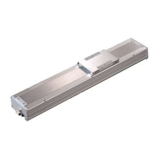
ECS Series
Food manufacturing processes
ECS FP Series
Compatible with Secondary Battery
ECS P4 Series
INSTRUCTION MANUAL
INSTRUCTION MANUAL
SM-A48287-A
• Be sure to read this instruction manual before using the product.
• Pay extra attention to the instructions concerning safety.
• After reading this instruction manual, keep it in a safe and convenient place.
Advertisement
Table of Contents

Related Manuals for CKD ECS Series


Summary of Contents for CKD ECS Series
- Page 1 Electric Actuator (compatible with stepper motors) ECS Series Food manufacturing processes ECS FP Series Compatible with Secondary Battery ECS P4 Series INSTRUCTION MANUAL INSTRUCTION MANUAL SM-A48287-A • Be sure to read this instruction manual before using the product. • Pay extra attention to the instructions concerning safety.
-
Page 2: Introduction
• Since our customers use this product for a very wide range of applications, CKD cannot keep track of all of them. Depending on the application and usage, the product may not be able to perform at its full potential due to fluid, wiring or other conditions, or it may lead to an accident. -
Page 3: For Safe Operation
To do so, make sure that the mechanism of the equipment and the system that controls it electrically are safe. In order to use CKD products safely, it is important to appropriately select, use, handle and maintain products. To secure product safety, be sure to observe the warnings and precautions described in this Instruction Manual. -
Page 4: Precautions Related To The Product
SM-A48287-A For Safe Operation Precautions related to the product DANGER Do not use this product for the following purposes. • Medical equipment related to sustainment and control of human life or body • Mechanical devices and mechanisms designed for the purpose of moving or transporting people •... -
Page 5: Table Of Contents
Product Overview ..................... 1 System Overview ....................1 1.1.1 System Configuration ................... 1 1.2 Model number ....................... 2 1.2.1 ECS Series (compatible with stepper motors) ..........2 1.3 Specifications ......................5 1.3.1 Specifications ....................5 Installation ........................ 7 2.1 Installation environment ..................10 2.2 Unpacking ...................... -
Page 6: Product Overview
Sensors can be added by choosing specific models. Inside sensor Inside sensor dog Outside sensor Outside sensor dog ECS Series Motor installation direction Four models available for different installation positions Motor Exposed Left side/belt drive Right side/belt drive Bottom/belt drive... -
Page 7: Model Number
SM-A48287-A 1. Product Overview 1.2 Model number 1.2.1 ECS Series (compatible with stepper motors) D E F G H I Symbol Description Body size (mm) Width 51 × height 54 Model No. × height 56 Width 65 × height 78.5 Width 102 ×... - Page 8 SM-A48287-A 1. Product Overview Table 1: (B) Thread lead and (C) stroke length (B) Thread lead (mm) (C) Stroke length (mm) Model (50 mm pitch) ○ ○ ○ 50-800 ○ ○ ○ 50-800 ○ ○ ○ ○ 50-1050 ○ ○ ○...
- Page 9 SM-A48287-A 1. Product Overview Table 5: (J) Grease nipple (J) Gr se nipple Model Motor Bottom / Belt Right side / Left side / Exposed drive Belt drive Belt drive For N only (Body installation direction: Standard (lower side 05 to 06 only)) 10 to 14 N/R/L...
-
Page 10: Specifications
SM-A48287-A 1. Product Overview 1.3 Specifications 1.3.1 Specifications [Applicable motor size: A <□42>] Item Model ECS-05 ECS-06 Ball screw diameter (mm) Ball screw precision grade Stroke length *1 (mm) 50 to 800 Thread lead (mm) Horizontal (kg) Max. load capacity *2 Vertical (kg) Max. - Page 11 SM-A48287-A 1. Product Overview Stroke and maximum speed Stroke (mm) and max. speed (mm/s) Model No. Thread Applicable lead motor size (mm) ・・・ 13.53 seconds □42 ECS-05 5.53 seconds 2.87 seconds 13.53 seconds □42 ECS-06 5.53 seconds 2.87 seconds 8.60 seconds □56 4.40 seconds ECS-10...
-
Page 12: Installation
SM-A48287-A 2. Installation 2. Installation DANGER Do not operate the product where there are hazardous materials such as combustibles, flammables, and explosives. The product may ignite, catch fire, or explode. Avoid splashing water or oil on the product. They may cause fire, electric leakage or product failure. Do not use oil droplets or oil mist. Securely hold and lock the product (including workpieces) when installing the product. - Page 13 SM-A48287-A 2. Installation WARNING Do not mount the product on flammable materials. Attachment of the product directly to or near flammable items could cause fire. Design the safety circuit/device so that the product’s movement causes no damage to the operator or equipment if the machine stops due to emergency stop, power outage, or other system errors.
- Page 14 SM-A48287-A 2. Installation CAUTION The wiring shall be such that inductive noise is not applied. • Avoid places where large currents or strong magnetic fields are generated. • Do not use the same piping or wiring (by multi-core cable) as other large motor power lines than this product.
-
Page 15: Installation Environment
SM-A48287-A 2. Installation 2.1 Installation environment • Check the ambient temperature and atmosphere of the product specifications for product storage and operation. • Use the product in a place where the ambient temperature is 0 to 40°C. Ventilate the place if the heat is trapped there. -
Page 16: Installation Method
SM-A48287-A 2. Installation 2.3 Installation method 2.3.1 Accessories <Basic type> Motor-mounting bolt (common to all motor installation directions) Specifications of the Model No. Motor size Size Quantity installed motor ECS-05 A <□42> ECS-06 ECS-10 B <□56> ECS-12 C <□60> ECS-14 <Per motor installation direction>... -
Page 17: Motor Installation Method
SM-A48287-A 2. Installation 2.3.2 Motor installation method • Installing and adjusting a motor requires expertise and technical skills. The work may be hazardous for individuals not having such expertise. • Before work, always power down the motor and sensors. Failure to do so may damage the product. - Page 18 SM-A48287-A 2. Installation Install the dustproof plate retainer and tighten the two dustproof plate mounting bolts. Install the cover on the coupling and tighten the (10) four mounting bolts of the cover. (11) The motor installation is completed. 2021-11-09...
- Page 19 SM-A48287-A 2. Installation <Body size: 05 to 06 Motor installation direction: R (right side/belt drive), L (left side/belt drive), D (bottom/belt drive)> Order Procedure Description Remove the four mounting bolts fixing the belt cover and the four mounting bolts of the motor plate.
- Page 20 SM-A48287-A 2. Installation <Body Size: 10 to 14 Motor installation direction: E (Motor Exposed)> Order Procedure Description Remove the four actuator top cover mounting bolts and the top cover. Loosen the coupling-fixing bolt on the motor side. Check that there is no foreign object on the mounting surface, and then install the motor.
- Page 21 SM-A48287-A 2. Installation <Body size: 10 to 14 Motor installation direction: R (right side/belt drive), L (left side/belt drive), D (bottom/belt drive)> Order Procedure Photographic description Remove the four mounting bolts fixing the belt cover and the four mounting bolts of the motor plate.
- Page 22 SM-A48287-A 2. Installation Belt tension for belt-drive type motors Tightening torque when engaging motor shaft with pulley Tightening torque Model No. Belt tension (N) Screw size (N・m) 1.7±10% ECS-05 12 to 17 ECS-06 12 to 17 3.7±10% 6.7±10% ECS-10 32 to 42 9.7±10% ECS-12 32 to 42...
-
Page 23: Dimensions Of Motor Attachment
SM-A48287-A 2. Installation 2.3.3 Dimensions of Motor Attachment [ECS-05-*****-E] 4-A (Screw hole) (Motor mounting) Specifications of Motor mounting the installed motor bolt Φ3.6 4-M3×L16 Φ3.6 4-M3×L16 [ECS-05-*****-R/L/D] 4-A (Screw hole) (Motor mounting) Specifications of Motor mounting the installed motor bolt Φ3.4 4-M3×L14 Φ3.4... - Page 24 SM-A48287-A 2. Installation [ECS-06-*****-E] 4-A (Screw hole) (Motor mounting) Specifications of Motor mounting the installed motor bolt Φ3.5 4-M3×L16 Φ3.5 4-M3×L16 [ECS-06-*****-R/L/D] 4-A (Screw hole) (Motor mounting) Specifications of Motor mounting the installed motor bolt Φ3.5 4-M3×L12 Φ3.5 4-M3×L12 2021-11-09...
- Page 25 SM-A48287-A 2. Installation [ECS-10-*****-E] (Motor Size: B <□56>) 4-A (Screw hole) (Motor mounting) [ECS-10-*****-E] (Motor Size: C <□60>) 4-A (Screw hole) (Motor mounting) Specifications of Motor mounting Motor size the installed motor bolt C <□60> 4-M4×L12 B <□56> 47.14 6.35 4-M4×L12 B <□56>...
- Page 26 SM-A48287-A 2. Installation [ECS-10-*****-R/L/D] (Motor Size: B <□56>) 4-A (Screw hole) (Motor mounting) [ECS-10-*****-R/L/D] (Motor Size: C <□60>) 4-A (Screw hole) (Motor mounting) Specifications of Motor mounting Motor size the installed motor bolt C <□60> 4-M4×L16 B <□56> 47.14 6.35 4-M4×L16 B <□56>...
- Page 27 SM-A48287-A 2. Installation [ECS-12-*****-E] (Motor Size: B <□56>) 4-A (Screw hole) (Motor mounting) [ECS-12-*****-E] (Motor Size: C <□60>) 4-A (Screw hole) (Motor mounting) Specifications of Motor mounting Motor size the installed motor bolt C <□60> 4-M4×L16 B <□56> 47.14 6.35 4-M4×L16 B <□56>...
- Page 28 SM-A48287-A 2. Installation [ECS-12-*****-R/L/D] (Motor Size: B <□56>) 4-A (Screw hole) (Motor mounting) [ECS-12-*****-R/L/D] (Motor Size: C <□60>) 4-A (Screw hole) (Motor mounting) Specifications of Motor mounting Motor size the installed motor bolt C <□60> 4-M4×L16 B <□56> 47.14 6.35 4-M4×L16 B <□56>...
- Page 29 SM-A48287-A 2. Installation [ECS-14-*****-E] (Motor Size: B <□56>) 4-A (Screw hole) (Motor mounting) [ECS-14-*****-E] (Motor Size: C <□60>) 4-A (Screw hole) (Motor mounting) Specifications of Motor mounting Motor size the installed motor bolt C <□60> 4-M4×L16 B <□56> 47.14 6.35 4-M4×L16 B <□56>...
- Page 30 SM-A48287-A 2. Installation [ECS-14-*****-R/L/D] (Motor Size: B <□56>) 4-A (Screw hole) (Motor mounting) [ECS-14-*****-R/L/D] (Motor Size: C <□60>) 4-A (Screw hole) (Motor mounting) Specifications of Motor mounting Motor size the installed motor bolt C <□60> 4-M4×L20 B <□56> 47.14 6.35 4-M4×L20 B <□56>...
-
Page 31: Installation Of Main Body And Transfers
SM-A48287-A 2. Installation 2.3.4 Installation of main body and transfers • The flatness of the mounting surface where the actuator is installed should be 0.05 mm/200 mm or less, and do not give twist or bending force to the product. Installing the actuator on an uneven surface may result in damage or malfunction of the product. -
Page 32: How To Use
SM-A48287-A 3. How to Use 3. How to Use 3.1 Precautions on Use WARNING Ensure the safety of the operating range of the device before supplying electricity to the product. Carelessly supplying power to it may lead to an electric shock or injury. Do not enter the operating range when the product is ready to operate. - Page 33 SM-A48287-A 3. How to Use CAUTION If the belt drive causes vibration, change the set speed so that vibration does not occur. The product may vibrate even within the operating speed range depending on the operating conditions. In belt drive type motors, wear particles are generated from the belt. Please be careful when you use it at the installation place and above the workpiece.
-
Page 34: Maintenance And Inspection
SM-A48287-A 4. Maintenance and inspection 4. Maintenance and inspection WARNING Do not perform wiring before installing the product. Doing so may result in an electric shock. Do not work with wet hands. Doing so may result in an electric shock. Do not perform wiring and inspection before 5 minutes or more have passed after the power is turned off and before the voltage is checked with a tester. -
Page 35: Periodical Inspection
SM-A48287-A 4. Maintenance and inspection 4.1 Periodical inspection In order to use the product in the optimum conditions, perform two to three periodical inspections per year. Check the timing belt every 500 km. 4.1.1 Inspection Items Be sure to turn off the power before performing the check items 1, 2, 3 and 4 below. Inspection Items Inspection Methods Treatment method... -
Page 36: Greasing
Recommended grease AFEP2 (YAMABARA) Standard series ETS FP series Super Lube (Synco Chemical) (multipurpose grease) Contact your nearest CKD sales office. ETS P4 series a) Model equipped with grease nipple: Pump grease through the grease nipple on the slider part. -
Page 37: Warranty Provision
5.1 Warranty conditions Scope of warranty If the product becomes defective for reasons attributable to CKD during the period of warranty indicated below, CKD will provide a replacement for the product, provide necessary replacement parts, or repair the product at no charge to the customer.
Need help?
Do you have a question about the ECS Series and is the answer not in the manual?
Questions and answers