Table of Contents
Advertisement
Quick Links
Advertisement
Table of Contents

Related Manuals for CKD EVD-1000 Series


Summary of Contents for CKD EVD-1000 Series
- Page 1 Digital Electro-pneumatic Regulator EVD-1000/3000 Series IO-Link Type INSTRUCTION MANUAL SM-A20758-A/3 • Read this Instruction Manual before using the product. • Read the safety notes carefully. • Keep this Instruction Manual in a safe and convenient place for future reference.
-
Page 2: Preface
• Since there are a wide variety of customer applications, it is impossible for CKD to be aware of all of them. Depending on the application or usage, the product may not be able to exercise its full performance or an accident may occur due to fluid, piping, or other conditions. -
Page 3: Safety Information
SM-A20758-A/3 SAFETY INFORMATION SAFETY INFORMATION When designing and manufacturing any device incorporating the product, the manufacturer has an obligation to ensure that the device is safe. To that end, make sure that the safety of the machine mechanism of the device, the pneumatic control circuit, and the electric system that controls such mechanism is ensured. -
Page 4: Precautions On Product Use
SM-A20758-A/3 SAFETY INFORMATION Precautions on Product Use DANGER Use the product within the specified voltage range. Applying voltage beyond the specified range may cause a malfunction, damage to the sensor, electric shock, or fire. Do not connect a load exceeding the rated output. The output circuit may become damaged or a fire may occur. - Page 5 Before using the product as an air blow with the control pressure of the secondary side released to the atmosphere, test the usage under actual conditions of use or contact CKD. The pressure may fluctuate depending on the piping and blowing conditions.
- Page 6 SM-A20758-A/3 SAFETY INFORMATION CAUTION and cause damage. If 0 MPa is required, bleed the secondary side or install a 3-way valve to release the pressure to the atmosphere. Although the pressure control range of the product includes 0 MPa, the pressure on the secondary side will not be completely released (the pressure of 1%FS or less of the maximum control pressure will remain).
-
Page 7: Table Of Contents
SM-A20758-A/3 CONTENTS CONTENTS PREFACE ........................... i SAFETY INFORMATION ....................ii Precautions on Product Use ..................iii Precautions on Design and Selection ................iii CONTENTS ........................vi PRODUCT OVERVIEW ..................... 1 Part Name ......................1 Body ........................ 1 Names and functions of display and operation panel ........3 Functions...................... -
Page 8: Contents
SM-A20758-A/3 CONTENTS Control procedure using IO-Link communication ..........48 Normal Mode ....................48 Preset input ....................50 Direct memory input ..................52 Monitoring overactive state of solenoid valve ........... 53 Monitoring overactive state of solenoid valve ..........53 Acquired data ....................53 How to obtain data .................. -
Page 9: Product Overview
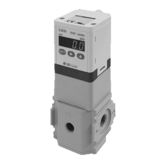
SM-A20758-A/3 1. PRODUCT OVERVIEW 1. PRODUCT OVERVIEW Part Name Body ◼ EVD-1000 Series M12,4pin connector LED display Operation keys Port R (pilot air exhaust) Threaded hole for mounting the bracket Option KA type only Exhaust port (main air exhaust) *Please attach the unit label sticker according to the unit to be used. - Page 10 SM-A20758-A/3 1. PRODUCT OVERVIEW ◼ EVD-3000 Series M12,4pin connector LED display Operation keys Port R (pilot air exhaust) Exhaust port Threaded hole for mounting the bracket (main air exhaust) Option KA type only *Please attach the unit label sticker according to the unit to be used. Unit label sticker (Accessory) 2020-10-06...
-
Page 11: Names And Functions Of Display And Operation Panel
SM-A20758-A/3 1. PRODUCT OVERVIEW Names and functions of display and operation panel 3-digit number LED display (green) Output display (red) ⚫ In the RUN mode (pressure display), the pressure or ⚫ "F" is displayed during function setting function setting data is displayed. confirmation. -
Page 12: Functions
SM-A20758-A/3 1. PRODUCT OVERVIEW Functions Related Screen Description Details (run mode) Setting details (setting mode) page Pressure Indicates the secondary side display pressure with 3-digit number. The display value is converted to the set unit. △ Input signal Indicates the selected input Input type can be selected from P.32 Screen F1... - Page 13 SM-A20758-A/3 1. PRODUCT OVERVIEW From screen F4 Related Screen Description Details (run mode) Setting details (setting mode) page Proportional Indicates the validity of Select to either using the P.34 Screen F5 value proportional value standard value or changing the P.42 change change and its set level.
-
Page 14: Model Number Indication
SM-A20758-A/3 1. PRODUCT OVERVIEW Model Number Indication ◼ EVD-1000 Series EVD-1 Description Symbol Pressure specification Pressure specification 100kPa 500kPa 900kPa Input specification Input specification IO-Link Port size Port size Rc1/4 G1/4 NPT1/4 Unit change Unit change Blank Unit change none... - Page 15 SM-A20758-A/3 1. PRODUCT OVERVIEW ◼ EVD-3000 Series EVD-3 Description Symbol Pressure specification Pressure specification 100kPa 500kPa 900kPa Input specification Input specification IO-Link Port size Port size Rc1/4 Rc3/8 G1/4 G3/8 NPT1/4 NPT3/8 Unit change Unit change Blank Unit change none Unit change available Option Option...
-
Page 16: Specifications
SM-A20758-A/3 1. PRODUCT OVERVIEW Specifications ◼ EVD-1100-C (maximum pressure: 100 kPa) EVD-1100-C [*2] [*3]- [*4] [*] -3 Item Clean compressed air (equivalent to ISO Class 1. 3. 2) Working fluid 160 kPa Max. working pressure Control pressure +50 kPa Min. working pressure 240 kPa Inlet side Proof pressure... - Page 17 SM-A20758-A/3 1. PRODUCT OVERVIEW ◼ EVD-1500-C (maximum pressure: 500 kPa) EVD-1500-C [*2] [*3]- [*4] [*5]-3 Item Clean compressed air (equivalent to ISO Class 1. 3. 2) Working fluid 700 kPa Max. working pressure Control pressure +100 kPa Min. working pressure 1050 kPa Inlet side Proof pressure...
- Page 18 SM-A20758-A/3 1. PRODUCT OVERVIEW ◼ EVD-1900-C (maximum pressure: 900 kPa) EVD-1900-C [*2] [*3]- [*4] [*5]-3 Item Clean compressed air (equivalent to ISO Class 1. 3. 2) Working fluid 1000 kPa Max. working pressure Control pressure +100 kPa Min. working pressure 1500 kPa Inlet side Proof pressure...
- Page 19 SM-A20758-A/3 1. PRODUCT OVERVIEW ◼ EVD-3100-C (maximum pressure:100kPa) EVD-3100- C [*2] [*3]- [*4] [*5]-3 Item Clean compressed air (equivalent to ISO Class 1. 3. 2) Working fluid 160 kPa Max. working pressure Control pressure +50 kPa Min. working pressure 240 kPa Inlet side Proof pressure 150 kPa...
- Page 20 SM-A20758-A/3 1. PRODUCT OVERVIEW ◼ EVD-3500-C (maximum pressure:500kPa) EVD-3500- C [*2] [*3]- [*4] [*5]-3 Item Clean compressed air (equivalent to ISO Class 1. 3. 2) Working fluid 700 kPa Max. working pressure Control pressure +100 kPa Min. working pressure 1050 kPa Inlet side Proof pressure 750 kPa...
- Page 21 SM-A20758-A/3 1. PRODUCT OVERVIEW ◼ EVD-3900-C (maximum pressure:900kPa) EVD-3900-C [*2] [*3]- [*4] [*5]-3 Item Clean compressed air (equivalent to ISO Class 1. 3. 2) Working fluid 1000 kPa Max. working pressure Control pressure +100 kPa Min. working pressure 1500 kPa Inlet side Proof pressure 1350 kPa...
-
Page 22: Communication Specifications
SM-A20758-A/3 1. PRODUCT OVERVIEW Communication specifications General Item Details Item Details Communication protocol IO-Link Min Cycle Times 2 ms Communication protocol revision V1.1 Data Storage 1 k byte Transmission rate COM3(230.4 kbps) SIO Mode support None Port Type Class A Device ID Refer to the table below Process Data (Input) -
Page 23: On Demand Data
On demand data ◼ Identification Vendor ID:855(Decimal number)/ 357(Hexadecimal number) Data Index Item Value Access Format index Length 0x0010 Vendor Name CKD Corporation 64 byte String 0x0011 Vendor Text https://www.ckd.co.jp/ 64 byte String 0x0012 Product Name EVD-1500-C**-****-3 Note 1 40 byte... -
Page 24: Parameter And Commands
SM-A20758-A/3 1. PRODUCT OVERVIEW Parameter and commands ◼ Common specification Data Index Item Value Access Format index Length 0x0002 1 byte UInteger8 System Command Refer to the "Table 1" 0x0000: No lock 0x000C 0x0001: Parameter lock 2 byte Record Device Access Locks 0x0002:... - Page 25 SM-A20758-A/3 1. PRODUCT OVERVIEW ◼ Individual specification Data Data Index Item Value Access Format index storage length 0: OFF Control stop function at 0x0100 2 byte UInteger16 zero input signal 1: ON 0: OFF Switch output 1 0x0101 1: Mode 1 2 byte UInteger16 Mode Selection...
- Page 26 SM-A20758-A/3 1. PRODUCT OVERVIEW Data Data Index Item Value Access Format index storage length 0x0112 2 byte Integer16 Preset memory 3 Setting range: Depends on the pressure range. 0x0113 2 byte Integer16 Preset memory 4 Setting range: Depends on the pressure range. 0x0114 2 byte Integer16...
-
Page 27: Process Data In
SM-A20758-A/3 1. PRODUCT OVERVIEW Process data IN Data Name Set Value for pressure 2byte Data Range Format UInteger16 Data Name Control pressure 2byte Data Range Format UInteger16 Switch Input Start Normal output Data Name Error Warning Select /Stop Operation Error Code True/False 0 to 15 0 to 2... -
Page 28: Process Data Out
SM-A20758-A/3 1. PRODUCT OVERVIEW Process data OUT CAUTION Start energization to this product after clearing Process Data OUT to "0 ". Unintended pressure may occur. The setting in this product can be changed with IO-Link communication from the master to the device (this product) and key operation. -
Page 29: Diagnosis
SM-A20758-A/3 1. PRODUCT OVERVIEW Diagnosis Event Device Error Type Cause Solution Code Status Code 0x8D02 E 01 ・Turn on the power again. Error Failure Supplied power voltage is outside the rated range. (Detected at 19.5 VDC or less detection accuracy ±10 %) 0x8D03 E 02 ・Check the Input settings... -
Page 30: Dimensions
SM-A20758-A/3 1. PRODUCT OVERVIEW Dimensions ◼ EVD-1000 Series M12,4pin connector φ4.2 Port R (Pilot air exhaust port) 2-(Select by port diameter) Rc1/4 G1/4 4-M3 depth6 NPT1/4 φ5.3 EXH port 2020-10-06... - Page 31 SM-A20758-A/3 1. PRODUCT OVERVIEW ◼ EVD-3000 Series M12,4pin connector φ4.2 Port R (Pilot air exhaust port) 2-(Select by port diameter) EXH port Rc1/4 (Select by port diameter) G1/4 Rc3/8 NPT1/4 Rc3/8 G3/8 G3/8 NPT3/8 NPT3/8 2-M4 depth12 2020-10-06...
-
Page 32: Internal Structure
SM-A20758-A/3 1. PRODUCT OVERVIEW Internal Structure ◼ EVD-1000 Series Part name Material ① PBT resin ② M12 connector ――― ③ Housing ABS resin ④ ――― Controller board ⑤ ――― 3-way valve ⑥ Valve base Polyphenylene sulfide resin ⑦ Pilot chamber Polyphenylene sulfide resin ⑧... - Page 33 SM-A20758-A/3 1. PRODUCT OVERVIEW ◼ EVD-3000 Series Part name Material ① PBT resin ② M12 connector ――― ③ Housing ABS resin ④ ――― Controller board ⑤ ――― 3-way valve ⑥ Valve base Polyphenylene sulfide resin ⑦ Pilot chamber Polyphenylene sulfide resin ⑧...
-
Page 34: Installation
Install a pneumatic filter immediately before the circuit in which pneumatic components are used. Install the product so that the exhaust port is not blocked and there is sufficient space for exhaust. ・EVD-1000 Series ・EVD-3000 Series Pilot exhaust air Wall... - Page 35 SM-A20758-A/3 2. INSTALLATION Attach the optional bracket to the bottom of the product. For the optional bracket, refer to "6.1 Optional Part Model Number". • EVD-1000 Series B-type can be installed in both directions. Cross headed pan B-type bracket L-type bracket...
-
Page 36: Piping
SM-A20758-A/3 2. INSTALLATION Piping CAUTION Do not remove the port seal until just before piping. If the port seal is removed before ready to begin piping, foreign matters may enter from the piping ports and cause a failure or malfunction. Fully flush and clean the air pipe before use. -
Page 37: Wiring
SM-A20758-A/3 2. INSTALLATION Wiring WARNING Check the connector pins and the cable conductor colors before wiring. Incorrect wiring may cause damage, failure, and malfunctions of the product. Check the wire color described in the Instruction Manual before wiring. Check the wiring insulation. Make sure that the wires do not contact other circuits and there is no ground fault and insulation failure between terminals. -
Page 38: M12 Connector
Recommended torque: 0.4 to 0.49 N · m Hold the M12 connector firmly so that it faces up or sideways when inserting it. The rotating mechanism of the Connector housing allows a 90-degree rotation. • EVD-1000 Series Hold firmly when inserting the connector. -
Page 39: Cable Connection
SM-A20758-A/3 2. INSTALLATION Cable connection ③ (Blue) ①L+(24 VDC) Brown ②N.C. White ② (White) Main ① (Brown) circuit ③L-(GND) Blue ④C(IO-Link) Black ④ (Black) IO-Link Master EVD (Device) Option Name Cable Color Brown L+(24 VDC) ① ② White N.C. ③ Blue L-(GND) Black... -
Page 40: Usage
SM-A20758-A/3 3. USAGE 3. USAGE CAUTION Create a program and control circuit that ignores signals for approximately two seconds immediately after energized. Pressure control will not operate for approximately two seconds immediately after energized for self-diagnosis. Stop the device before changing the set output value. Control system devices may operate unintentionally. -
Page 41: Automatic Power Off
SM-A20758-A/3 3. USAGE Automatic power off The F3 screen shows whether the automatic power off is enabled or disabled. When the function is disabled: When the function is enabled: Switch output The F4 screen shows whether the switch output is enabled or disabled and its set value. •... -
Page 42: Proportional Value Change
SM-A20758-A/3 3. USAGE Proportional value change In the F5 screen, whether the proportional value change is enabled or disabled and its set level can be When the function is disabled (standard value)* factory setting confirmed. When "Lower proportional value" is •... -
Page 43: Operation While Communication Error Occurred Setting
SM-A20758-A/3 3. USAGE Operation while communication error occurred setting The F7 screen shows whether the operation while communication error occurred setting is its set value. HOLD: CLEAR: Control stop function at zero input signal The F8 screen shows whether the control stop function at zero input signal is enabled or disabled. When the function is disabled: When the function is enabled: 2020-10-06... -
Page 44: How To Set (Setting Mode)
SM-A20758-A/3 3. USAGE How to Set (Setting Mode) Setting ranges Function Display Description Specification F1: Input specification setting Range: Note 1 - For Preset Mode - 1100 / 000 to 100 "F1.P1", "F1.P8" Sets a set value (pressure). 確定後、設定モード画面を継続。 1500 / 000 to 500 1900 / 000 to 900 Min. -
Page 45: Key Lock
SM-A20758-A/3 3. USAGE Key lock Key lock prevents incorrect operation. When the power is turned on (including re-turn on), the key is locked. Release the key lock before changing the setting. ◼ How to operation (Key operation) • Release key lock Press &... - Page 46 SM-A20758-A/3 3. USAGE ◼ Preset input Press and hold the [SET] key at least two seconds with the preset input selected in F1 screen. Enter the set value key: Shifts the digit. key: Increases the value. At least 2 seconds key: Confirm the data ->...
-
Page 47: Automatic Power Off
SM-A20758-A/3 3. USAGE Automatic power off ◼ How to operation (Key operation) In F3 screen, press and hold the [SET] key at least two seconds to switch to the setting mode. At least 2 seconds When automatic power off function is not used *Factory setting After the data is confirmed, the setting mode is canceled and returns to screen F3. -
Page 48: Switch Output
SM-A20758-A/3 3. USAGE Switch output < Mode 1 > < Mode 2 > H (+ tolerance limit) H (upper limit) Input signal setting L (- tolerance limit) L (lower limit) limit) Output Output ◼ How to operation (Key operation) In F4_1 and F4_2 screen, press and hold the [SET] key at least two seconds to switch to the setting mode. - Page 49 SM-A20758-A/3 3. USAGE ◼ How to operation (IO-Link communication) <Parameter settings> Parameter and Command Switch output 1 setting • Switch output 1 OFF setting Index Item Value Index Index: Write "0: OFF" to 0x0101. 0: OFF Switch output 1 0x0101 1: Mode 1 •...
-
Page 50: Proportional Value Change Setting
SM-A20758-A/3 3. USAGE Proportional value change setting ◼ How to operation (Key operation) In the F5 screen, press and hold the [SET] key at least two seconds to switch to the setting mode. If not using the proportional value change function *Factory setting After the data is confirmed, the setting mode is canceled and returns to screen F5. - Page 51 SM-A20758-A/3 3. USAGE ◼ How to operation (IO-Link communication) <Parameter settings> Parameter and Command • Standard setting for proportional value Index: Write "0: OFF" to 0x010B. Index Item Value Index 0: OFF • Increases proportional value setting Proportional value 1: Increases proportional value Index: Write "1: Increases proportional 0x010B setting...
-
Page 52: Unit Change (Ka Type)
SM-A20758-A/3 3. USAGE Unit change (KA type) ◼ How to operation (Key operation) In the F6 screen, press and hold the [SET] key at least two seconds to switch to the setting mode. * For domestic models, data is displayed on the left and data cannot be set. -
Page 53: Operation While Communication Error Occurred Setting
SM-A20758-A/3 3. USAGE Operation while communication error occurred setting ◼ How to operation (Key operation) In the F7 screen, press and hold the [SET] key at least two seconds to switch to the setting mode. For HOLD setting at the time of communication error *Factory setting After the data is confirmed, the setting mode is canceled and returns to screen F7. -
Page 54: Control Stop Function At Zero Input Signal
SM-A20758-A/3 3. USAGE Control stop function at zero input signal ◼ How to operation (Key operation) In the F8 screen, press and hold the [SET] key at least two seconds to switch to the setting mode. At least 2 seconds When the input zero operation function is not used *Factory setting After the data is confirmed, the setting mode is canceled and... -
Page 55: Factory Setting Mode (Initialization)
SM-A20758-A/3 3. USAGE Factory setting mode (initialization) ◼ How to initialize <Initialization in progress> Press & hold both <Completed> at least 2 seconds. • Factory setting Function Name Display of setting Description of setting 入力信号タイプ記号 内容 IO-Link 通信 16bit 入力 Input specification setting Normal Mode オートパワーオフ機能の有効/無効が確認できます。... -
Page 56: Control Procedure Using Io-Link Communication
SM-A20758-A/3 3. USAGE Control procedure using IO-Link communication Normal Mode The pressure can be controlled with the "Set Value for pressure" of the Process Data OUT. The set value cannot be changed by key operation. ◼ Setting method using IO-Link communication [Parameter setting] Parameter and Command •... - Page 57 SM-A20758-A/3 3. USAGE [Confirmation] Process Data IN Data name Set pressure: The value of the "Set value for pressure" of the Process Data OUT is displayed here. Data name Controlled pressure: EVD’s controlled pressure value is displayed here. Switch Normal output Data name Error...
-
Page 58: Preset Input
SM-A20758-A/3 3. USAGE Preset input Switch the set pressure by specifying eight set pressures and using the three bits of the Process Data OUT. Ex.) To control the set pressure (0, 50, 100, 150, 200, 300, 400 or 500 kPa) with preset input Select Preset Mode for "Input setting". - Page 59 SM-A20758-A/3 3. USAGE [Operation] Process Data OUT Data name Set pressure Preset Data name Unused Unused Start/Stop • Setting active state (pressure controlled state) Set the "Start/Stop" bit of the Process Data OUT to "1" to Preset "Preset" of Process Data OUT create an active state.
-
Page 60: Direct Memory Input
SM-A20758-A/3 3. USAGE Direct memory input "Input setting" can be changed to the direct memory input mode in the IO-Link communication, but the direct memory value itself cannot be set. To set the value, use key operation. Changing the "Input setting"... -
Page 61: Monitoring Overactive State Of Solenoid Valve
SM-A20758-A/3 3. USAGE Monitoring overactive state of solenoid valve Monitoring overactive state of solenoid valve The IO-Link communication can be used to monitor the operating status of the two solenoid valves used inside the EVD and obtain data. An overactive state can occur even when the product is operating normally. Analyze this information on the overactive state to help select a model (EVD-1000 or EVD-3000, etc.) for your system. -
Page 62: How To Obtain Data
SM-A20758-A/3 3. USAGE [Confirmation] Process Data IN When the solenoid valve is operating in the overactive state, the "Warning" flag of the Process Data IN changes to "1: ON" and the code corresponding to the error code is displayed, besides updating the values of the above parameters. -
Page 63: Maintenance And Inspection
• Are the valves exhausting properly? ◼ Operation of pneumatic actuator • Are operations smooth? • Is the actuator reaching the end stop properly? • Are loads connected properly? If an abnormality is found, contact your nearest CKD sales office or distributor. 2020-10-06... -
Page 64: Troubleshooting
SM-A20758-A/3 5. TROUBLESHOOTING 5. TROUBLESHOOTING Problems, Causes, and Solutions If the product does not operate as intended, check the table below for a possible solution. Problem Cause Solution Release the key lock according to "3.2.2 Key lock" and Key is locked. change the settings. - Page 65 SM-A20758-A/3 5. TROUBLESHOOTING Problem Cause Solution Primary side pressure is output as Make sure that there is no abnormality in piping and wiring There is a failure in EVD. it is. and then replace the product. Check the Input signal type. Input signal is abnormal.
-
Page 66: Error Code
SM-A20758-A/3 5. TROUBLESHOOTING Error Code Turn off the power, check the cause of the error according to the table below, correct it, and turn on the power again. Event Control processing Error indication Name of error code Error description (Solenoid valve Classification (IO-Link) operation) -
Page 67: Optional Part Model Number
SM-A20758-A/3 6. OPTION 6. OPTION Optional Part Model Number EVD- Symbol Description Optional cable IO-Link (M12 Straight(female)/M12 Straight(male)) 3m IO-Link (M12 L Type(female)/M12 Straight(male)) 3m IO-Link (M12 One side straight(female)) 3m ●EVD-MS3 (Product side) ●EVD-ML3 (Product side) ●EVD-MM3 (Product side) Cable Color Name L+(DC24V) - Page 68 SM-A20758-A/3 6. OPTION EVD- Symbol Description Bracket option B-type bracket, floor mounted, EVD-1000 L-type bracket, wall mounted, EVD-1000 B-type bracket, floor mounted, EVD-3000 L-type bracket, wall mounted, EVD-3000 ●EVD-B1 ●EVD-L1 4-full R 4-full R ●EVD-B3 ●EVD-L3 4-full R 2020-10-06...
-
Page 69: References
SM-A20758-A/3 7. References 7. References Operating principle of digital electro-pneumatic regulator Operating principle The digital electro-pneumatic regulator performs feedback control to control the pilot pressure by detecting controlled pressure using a pressure sensor, and PWM-driving two-port solenoid valves for air supply and exhaust. - Page 70 Duty ratio Small ◼ EVD-1000 The EVD-1000 series includes the pilot control section described above and a booster section for improving the flow characteristics. The booster section includes air supply and exhaust valves and a diaphragm for opening and closing them. The exhaust valve is connected to the diaphragm. The lower chamber of the diaphragm has the same pressure as the controlled pressure.
-
Page 71: About Overactive State
SM-A20758-A/3 7. References ◼ EVD-3000 The EVD-3000 series includes the pilot control section described above and a booster section for improving flow characteristics. The booster section includes an air supply valve (top valve), an exhaust valve (bottom valve), and a piston assembly to open and close them. The exhaust valve is connected to the piston assembly. -
Page 72: Warranty Provisions
If the product specified herein fails for reasons attributable to CKD within the warranty period specified below, CKD will promptly provide a replacement for the faulty product or a part thereof or repair the faulty product at one of CKD’s facilities free of charge.
Need help?
Do you have a question about the EVD-1000 Series and is the answer not in the manual?
Questions and answers