
Related Manuals for CKD ESC4 Series


Summary of Contents for CKD ESC4 Series
- Page 1 ESC4 Series Controller for Electric Actuators INSTRUCTION MANUAL Read this Instruction Manual before using the product. In particular, read the safety notes carefully. Keep this Instruction Manual safe for use at any time. 2024-09-13 SM-A85796/2-A...
- Page 2 PREFACE Thank you for purchasing our controller "ESC4 Series" for electric actuators. This Instruction Manual describes basic matters related to the operation of this product in order to fully demonstrate its performance. Please read this Instruction Manual thoroughly and use the product properly.
- Page 3 SAFETY INFORMATION When designing and manufacturing any device incorporating the product, the manufacturer has an obligation to ensure that the device is safe. To that end, make sure that the safety of the machine mechanism of the device and the electric system that controls such mechanism is ensured.
- Page 4 <Warning symbol type> A general purpose mark A mark that prohibits touching indicating prohibited (not equipment. allowed) actions. A general purpose mark A mark that prohibits the act of indicating the danger such as putting a finger. electric shock and burn. A mark indicating the danger A general purpose mark that occurs when an automatic...
- Page 5 Precautions on Product Use DANGER Do not use this product for the following applications. Medical equipment pertaining to sustainment and management of human life and body Mechanism and mechanical device for transferring and transporting people Critical parts for securing safety in a mechanical device WARNING Never modify or implement additional processing to the product.
- Page 6 CONTENTS PREFACE ......................2 SAFETY INFORMATION ..................3 Precautions on Product Use ..................... 5 CONTENTS ......................6 1. PRODUCT OVERVIEW ..................8 System Structure ....................... 8 Instruction Manuals Related to This Product ............... 11 Part Name ......................... 12 Model Number Indication ....................14 2.
- Page 7 8. REFERENCE INFORMATION ................ 82 Specifications ........................82 Dimensions ........................83 Index ........................84 Glossary ......................85 2024-09-13 SM-A85796/2-A...
- Page 8 PRODUCT OVERVIEW System Structure System structure ◼ ESC4 Series Surge protector Controller: ESC4 series I/O cable power supply Noise filter for power supply Motor relay cable Switch relay cable Connectable actuators DSSD2 DSTG DSTS DSTK DMSDG DLSH DSTL DCKW ※ Refer to "1.4 Model Number Indication" for controller model numbers for the connectable actuators.
- Page 9 The following items can be purchased from us in the system configuration. Component Product name/Model No. This product Controller ESC4 Series MC 1,5/ 4-ST-3,81 Power supply Accessories connector (PHOENIX CONTACT) Screw drive system Spring drive system DSSD2 series DSTK series...
- Page 10 Workflow CAUTION Connect the controller that supports the actuator. If operated with unsupported controller, the actuator may operate unexpectedly. It may cause injury to people around it or failure of the actuator. Follow the steps below to wire and set the controller so that it can be operated from the PLC.
- Page 11 This Instruction Manual is "SM-A85796-A". The instruction manuals related to this product are as follows. Controller for Electric actuators Electric Actuator SM-A69055-A SM-A85796-A (this Instruction Manual) DSSD2 series ESC4 Series DSTK series DSTG series DSTS series DSTL series SM-A69064-A DMSDG series...
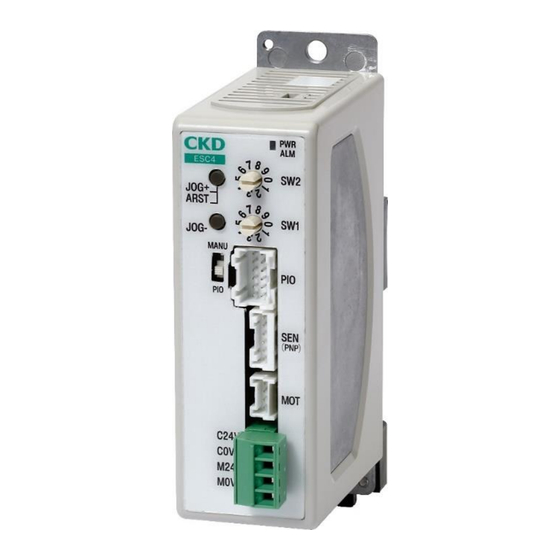
- Page 12 Part Name <Top> (Rear) V2, V3: Control mode selector switch (Front) <Front> PWR, ALM: Indicator lamps JOG(+), ARST: Jog(+), alarm reset switch SW2: Rotary switch 2 SW1: Rotary switch 1 JOG(-): Jog(-) switch MANU, PIO: PIO: IF connector Operation mode selector switch SEN: Switch connector MOT: Motor connector C24V, C0V,...
- Page 13 Code Part Name Description A switch to select the control mode. Control mode V2 represents the solenoid valve mode double 2-position type, and V3 V2, V3 selector represents the solenoid valve mode double 3-position type. switch Refer to "3.1.2 Setting the control mode" for the control mode. PWR represents the servo lamp and ALM represents the alarm lamp.
- Page 14 LED indication ◼ Servo lamp and alarm lamp Alarm Controller status Servo lamp (green) lamp (red) Control power OFF Motor energized state When operation mode PIO is selected Blinking Motor de- Normal energized state (Lit once per second) Blinking When operation mode MANU is selected (Lit once every 0.5 seconds) Blinking (Lit once...
- Page 15 Combination of actuator and controller model numbers ◼ Screw drive system Actuator Actuator model number Controller model number Model Size Lead group DSSD2-20SE-06***- ESC4-DP-0120-06*** T3PHN0AN DSSD2-20SE-09***- ESC4-DP-0120-09*** T3PHN0AN DSSD2-32SE-06***- ESC4-DP-0132-06*** T3PHN0AN DSSD2 DSSD2-32SE-12***- ESC4-DP-0132-12*** T3PHN0AN DSSD2-50SE-06***- ESC4-DP-0150-06*** T3PHN0AN DSSD2-50SE-12***- ESC4-DP-0150-12*** T3PHN0AN DSTK-M-20SE-06***- ESC4-DP-0220-06***...
- Page 16 Actuator Actuator model number Controller model number Model Size Lead group DSTS-M-20SE-06***- ESC4-DP-0420-06*** T3PHN0AN DSTS-M-20SE-09***- ESC4-DP-0420-09*** T3PHN0AN DSTS-M-32SE-06***- ESC4-DP-0432-06*** T3PHN0AN DSTS DSTS-M-32SE-12***- ESC4-DP-0432-12*** T3PHN0AN DSTS-M-50SE-06***- ESC4-DP-0450-06*** T3PHN0AN DSTS-M-50SE-12***- ESC4-DP-0450-12*** T3PHN0AN DSTL-M-20SE-06***- ESC4-DP-0520-06*** T3PHN0AN DSTL-M-20SE-09***- ESC4-DP-0520-09*** T3PHN0AN DSTL-M-32SE-06***- ESC4-DP-0532-06*** T3PHN0AN DSTL DSTL-M-32SE-12***- ESC4-DP-0532-12*** T3PHN0AN...
- Page 17 ◼ Spring drive system Actuator Actuator model number Controller model number Model Size Lead group DMSDG-08SH3** ESC4-DP-0608-NN*** F3PH-TN0AN DMSDG DMSDG-16SH5** ESC4-DP-0616-NN*** F3PH-TN0AN DLSH-20SH410NN ESC4-DP-0720-NNNNN F3PH-FN0AN DLSH DLSH-32SH622NN ESC4-DP-0732-NNNNN F3PH-FN0AN DCKW-20SH410NN ESC4-DP-0820-NNNNN F3PH-FN0AN DCKW DCKW-32SH608NN ESC4-DP-0832-NNNNN F3PH-FN0AN ※ The actuator model number is for a straight type switch, connector take-out direction: top or front, and without cable.
- Page 18 INSTALLATION DANGER Do not use the product in a place where dangerous substances such as ignitable, inflammable, or explosive materials are present. A fire, ignition, or explosion may occur. Do not work with wet hands. Doing so may cause electric shock. Prevent water and oil from splashing onto the product.
- Page 19 WARNING Do not install the product to a combustible material. If the product is installed near a combustible material, a fire may result. Do not place heavy objects on cables or pinch them. Otherwise, the cover of the cable may tear or excessive stress is applied, causing poor continuity and insulation degradation.
- Page 20 WARNING Design a safety circuit or safety device so that if the machine stops due to a system abnormality such as an emergency stop or a power failure, the equipment will not be damaged or personal injury will not occur. When wiring the product, refer to this Instruction Manual or any other relevant instruction manuals to make sure that the wiring is correct and connectors are firmly connected.
- Page 21 CAUTION Do not use the product in an environment where a strong magnetic field occurs. A malfunction may occur. Do not perform a withstand voltage test or an insulation resistance test on a device with the product installed. Due to the circuit design, the product may be damaged if a withstand voltage test or an insulation resistance test is performed on the device with the product installed.
- Page 22 CAUTION Install the wiring so that no induction noise is applied. Avoid a place where a large current or strong magnetic field occurs. Do not use the same piping or wiring (with multi-core cables) as the power line of a large motor other than the product. ...
- Page 23 CAUTION Observe the tightening torque when installing the cylinder switch. If the maximum tightening torque is exceeded, setscrews, brackets, switches, etc. may be damaged. In addition, if the switch is tightened with less than the minimum tightening torque, the switch mounting position may be shifted.
- Page 24 CAUTION If the switch is set to the center of the operating range, gripping force may be reduced during PUSH/closing operation. When performing electric welding to the equipment to which the product is installed, remove all the frame ground connections of the product.
- Page 25 Environment Before storing or using the product, check the ambient temperature and atmosphere specified in the product specifications. Use the product at an ambient temperature between 0°C and 40°C. Ventilate if heat can become trapped. Use the product at an ambient humidity between 35% and 85% RH. Do not use the product in a place where condensation occurs.
- Page 26 Unpacking CAUTION Do not carry heavy products alone. Do not stand on the package. In order to prevent deforming the package, do not place heavy objects and objects of which their load concentrates. Do not apply unnecessary force to any part of the product. When carrying or handling the product, use extreme care not to apply impact to the product (for example, do not drop the product).
- Page 27 Wiring Method WARNING Do not touch the charging part with bare hands. Doing so may cause electric shock. Perform the wiring with the power supply turned OFF. Touching the electrical wiring connections may result in electric shock. Read and fully understand this instruction manual before performing the electrical wiring.
- Page 28 Wiring with the power supply ◼ Power supply connector specifications <List of power supply connector terminals (MC 1,5/4-ST-3,81 (PHOENIX CONTACT))> Terminal name Function name Description of function Motive power supply Applies 0 VDC of the power supply. Note 1 M24V Power supply (+) Applies 24 VDC of the power supply.
- Page 29 ◼ Specifications of power supply circuit Item Specifications Motive power supply voltage 24 VDC ± 10% □35(DSSD2-20,DSTK-20, DSTG- 3.0 A or less 20,DSTS-20,DSTL-20) □42(DSSD2-32,DSTK-32, DSTG- Screw drive 3.0 A or less system 32,DSTS-32,DSTL-32) Power unit □56(DSSD2-50,DSTK-50, DSTG- consumption 3.0 A or less 50,DSTS-50,DSTL-32) current □20(DMSDG-08)
- Page 30 <Basic configuration of power supply> Surge protector Emergen cy stop Emergency switch stop reset switch 24 V 24 VDC Note 1 power Note 1 supply AC power supply Controller power supply connector M24V Note 1 C24V Note 1: To externally shut off the motive power supply for supporting safety categories, connect a contact from an electromagnetic switch or other device to the M24V terminal.
- Page 31 Use the dedicated relay cable to wire the controller and actuator. The combinations of controller and relay cable are as follows. Controller Relay cable Motor relay cable ESC3-M2-R□ ESC4 Series Switch relay cable ESC3-S2-R□ ◼ Motor relay cable model number system ESC3-M2-R Cable length 10 m ※...
- Page 32 ◼ Switch relay cable model number system ESC3-S2-R Cable length 10 m ※ The cable type is movable cable. ◼ Switch relay cable external dimensions Actuator side Controller side Switch 1 PULL/closing side Switch 2 PUSH/opening side L (cable length is according to the model number.) 2024-09-13 SM-A85796/2-A...
- Page 33 ◼ Wiring diagram of motor relay cable and switch relay cable CAUTION Reconfirm wiring prior to energizing to prevent wiring mistakes. <For DSSD2, DSTK, DSTG, DSTS, and DSTL series> Connect the lead wire of the motor to the motor relay cable. Connect the cylinder switch on the PUSH side to switch 2 of the switch relay cable.
- Page 34 <For DLSH and DCKW series> Connect the lead wire of the motor to the motor relay cable. Connect the cylinder switch on the opening side to switch 2 of the switch relay cable. Connect the cylinder switch on the closing side to switch 1 of the switch relay cable. Switch relay cable switch 2 (opening side) Motor relay cable...
- Page 35 Wiring with the I/O cable Use the dedicated I/O cable to wire the controller and the host device (PLC). ◼ I/O cable model number system ESC3-NP2- Cable length 10 m ◼ I/O cable dimensions Controller side Host device (PLC) side L (cable length is according to the model number.) 2024-09-13 SM-A85796/2-A...
- Page 36 ◼ I/O cable wiring diagram CAUTION Reconfirm wiring prior to energizing to prevent wiring mistakes. PLC output unit Controller 24 VDC Note 1 Pink (black 1) Alarm reset input COM Note 2 Output side COM Yellow (black 1) Alarm reset input 24 VDC Note 1 White (black 1)
- Page 37 ⚫ "NPN" indicates that NPN transistors are generally used in the output unit of a PLC in the connection of parallel I/O specification. Even if the NPN transistor is not used, if the − side of the external power supply is connected to the output COM (output common) and the + side of the external power supply is connected to the input COM (input common), the term NPN is used.
- Page 38 ◼ Input/output signal assignment <Signal name list> The table below lists the input and output signals. For details on the control mode, see "3.1.2 Setting the control mode". For details on the operation, see "3.2.1 Basic Operation". <Input signal> (PLC -> controller) Alarm reset input Explanation ON edge...
- Page 39 ◼ Input/output circuit <Input circuit> Item Specifications Number of inputs 3 points Input voltage 24 VDC ± 10% Input current 4 mA/point Minimum input current 3 mA or more when ON Maximum input current 0.5 mA or less when OFF Alarm reset input PUSH/opening operation input PULL/closing operation input...
- Page 40 USAGE DANGER Do not enter the operating range while the actuator can operate. An injury may occur. Do not work with wet hands. Doing so may cause electric shock. WARNING Do not climb on the product or put things on it. ...
- Page 41 CAUTION When the controller and actuator are connected with a cable, do not move the actuator moving part by external force except for manual operation. A malfunction or damage may occur due to regenerative currents. Do not dent or scratch the moving part of the actuator. ...
- Page 42 CAUTION When changing the combination of the actuator and controller, be sure to check the model numbers and settings before operating them. An accident may occur. Use the actuator so that no impact is applied to the moving part. Since the product life varies depending on the transfer load, etc., set it with sufficient margin.
- Page 43 Setting Setting the operation mode The operation mode can be set to MANU or PIO by the operation mode selector switch on the front of the controller. Operation Code Explanation mode This mode operates the actuator using the JOG(+) and JOG(-) switches on the front of the controller.
- Page 44 Setting the stop position The stop position of the actuator can be set by adjusting the position of the cylinder switch. ◼ DSSD2, DSTK, DSTG, DSTS, DSTL series Rotate the manual operation shaft to move the moving part of the actuator to the desired position.
- Page 45 ◼ DMSDG series Install the actuator so that it presses the workpiece within the effective pressing range. Insert a spacer of about 1 mm between the table and the workpiece. Rotate the manual operation shaft and gently press the table against the workpiece and spacer. Slide the cylinder switch of the PUSH side from outside the operating range and fix it in the position where the LED is lit.
- Page 46 ◼ DLSH series Fabricate and install an attachment so that the position to grip the workpiece is within the effective pressing range. Insert a spacer of about 1 mm between the finger and the workpiece. Rotate the manual operation shaft and gently grip the workpiece and spacer.
- Page 47 ◼ DCKW series Fabricate and install an attachment so that the position to grip the workpiece is within the effective pressing range. Insert a spacer of about 0.5 mm between the finger and the workpiece. Rotate the manual operation shaft and gently grip the workpiece and spacer.
- Page 48 Setting the speed The actuator speed can be set by the rotary switch on the front of the controller. Rotary switch 2 Rotary switch 1 ◼ DSSD2, DSTK, DSTG, DSTS, DSTL series Rotary switch 2: Sets the PUSH speed. Rotary switch 1: Sets the PULL speed. Units: mm/s Actuator model number Rotary switch settings...
- Page 49 ◼ DMSDG, DLSH, DCKW series Units: mm/s Rotary Switch 1: Sets both PUSH/opening speed and PULL/closing speed. Actuator model number Rotary switch settings Spring Series Size Direction lead PUSH PULL DMSDG PUSH PULL Opening Closing DLSH Opening Closing Opening Closing DCKW Opening Closing...
- Page 50 Setting the pressing and gripping forces On the DMSDG, DLSH and DCKW series, the pressing and gripping forces can be set by rotary switch 2 on the front of the controller. CAUTION DSSD2, DSTK, DSTG, DSTS and DSTL series do not support pressing operation.
- Page 51 ◼ DMSDG series DMSDG-08 Stroke 10 Rotary switch 2 (pressing force) setting Stroke 20 Rotary switch 2 (pressing force) setting 2024-09-13 SM-A85796/2-A...
- Page 52 Stroke 30 Rotary switch 2 (pressing force) setting ※ The pressing force are approximate. There will be an error due to pressing position and cylinder switch adjustment. ※ Pressing operation is possible only when PUSH. Pressing is not supported when PULL. ※...
- Page 53 Stroke 20 Rotary switch 2 (pressing force) setting Stroke 30 Rotary switch 2 (pressing force) setting ※ The pressing force are approximate. There will be an error due to pressing position and cylinder switch adjustment. ※ Pressing operation is possible only when PUSH. Pressing is not supported when PULL. ※...
- Page 54 ◼ DLSH series Rotary switch 2 (gripping force) setting Rotary switch 2 (gripping force) setting ※ The gripping force are approximate. There will be an error due to gripping position and cylinder switch adjustment. ※ This product is for gripping outside diameter. It does not support for gripping inner diameter. ※...
- Page 55 ◼ DCKW series Rotary switch 2 (gripping force) setting Rotary switch 2 (gripping force) setting ※ The gripping force are approximate. There will be an error due to gripping position and cylinder switch adjustment. ※ This product is for gripping outside diameter. It does not support for gripping inner diameter. ※...
- Page 56 Operation and Time Chart Basic Operation WARNING When turning the servo OFF, check that it is safe even if the actuator stops. If the servo is turned OFF during operation, the moving part may fall, causing injury or damage to the workpiece. CAUTION Do not change the power supply voltage after turning on the power.
- Page 57 ◼ Control mode: Solenoid valve mode double 2-position type <Input signal> PUSH/opening PULL/closing Description operation input operation input 1 ↑ Starts PUSH/opening operation. 1 ↑ Starts PULL/closing operation Retains the previous operation. × × 0: OFF (level input), 1 ↑: ON (edge input), x: Not specified (regardless of ON/OFF state) ※...
- Page 58 <Time-chart> Horizontal axis: Time 横軸:時間 PUSH/開 PUSH/opening operation input 動作入力 Input 入力信号 signal PULL/閉 PULL/closing operation input 動作入力 PUSH/開 PUSH/opening operation output 動作完了出力 Output 出力信号 signal PULL/閉 PULL/closing operation output 動作完了出力 PUSH/opening side PUSH/開側 cylinder switch position シリンダスイッチ位置 Displacement 変位 PULL/閉側...
- Page 59 ◼ Control mode: Solenoid valve mode double 3-position type <Input signal> PUSH/opening PULL/closing Description operation input operation input PUSH/opening operation PULL/closing operation Stop on the spot. Retains the previous operation. 0: OFF, 1: ON ※ Secure the state of each input signal at least 20 msec. <Output signal>...
- Page 60 <Time chart> Horizontal axis: Time 横軸:時間 PUSH/開 PUSH/opening operation input 動作入力 Input 入力信号 signal PULL/閉 PULL/closing operation input 動作入力 PUSH/開 PUSH/opening operation output 動作完了出力 Output 出力信号 signal PULL/閉 PULL/closing operation output 動作完了出力 PUSH/開側 PUSH/opening side cylinder switch position シリンダスイッチ位置 Displacement 変位...
- Page 61 ◼ JOG operation Use the following input and output signals for operation. Front panel switch Description JOG(-) JOG(+) 1 ↑ Starts JOG movement in the PUSH/opening direction. Stops JOG movement in the PUSH/opening direction. 1 ↑ Starts JOG movement in the PULL/closing direction. Stops JOG movement in the PULL/closing direction.
- Page 62 <Time-chart> Horizontal axis: Time JOG(+) switch JOG(-) Front panel switch switch MANU Operation mode selector switch Displacement Note 1 Note 1 JOG (+) JOG (+) JOG(-) JOG(-) travel start travel stop travel start travel stop Note 1: The jog travel start command that is continuously turned on takes precedence, and unless it is turned off once, the jog travel start command in the opposite direction is not accepted.
- Page 63 Emergency stop and cancellation WARNING When turning on the motive power supply, confirm that it is safe for the actuator to operate. The operation input signal is level input for the solenoid valve mode double 3-position type, so it may operate simultaneously with motive power supply ON.
- Page 64 Operation alarm If the cylinder switch cannot recognize both ends of the actuator for any reason, an operation alarm (cancelable alarm) is generated. The operation alarm is canceled by the alarm reset input (ON edge) or by the motive power supply OFF. <Input signal>...
- Page 65 ◼ Cancelation by alarm reset input <Time-chart> 横軸:時間 Horizontal axis: Time Power supply モータ電源 アラームリセット Input Alarm reset input 入力信号 signal 入力 Output Alarm output 出力信号 アラーム出力 signal LED (green) LED(緑) LED (red) LED(赤) (A) (B) ※ The above figure shows a time chart when the operation mode selector switch is switched to "PIO". When the operation mode selector switch is set to "MANU", the LED (green) blinks even when the motive power supply is (A)...
- Page 66 ◼ Cancellation by turning off the motive power supply <Time-chart> Horizontal axis: Time 横軸:時間 Power supply モータ電源 アラームリセット Input 入力信号 Alarm reset input 入力 signal Output 出力信号 アラーム出力 Alarm output signal LED (green) LED(緑) LED (red) LED(赤) (C) (A) (B) ※...
- Page 67 MAINTENANCE AND INSPECTION WARNING Do not perform disassembly or modification of products that are not specified in this manual. An injury, accident, malfunction, or failure may occur; in addition, the specifications described in this manual may not be satisfied. Do not attach or remove wires and connectors with the power turned ...
- Page 68 Precautions on Product Disposal CAUTION When disposing of the product, comply with “Waste Management and Public Cleansing Act” and have an industrial waste disposal company dispose of the product. 2024-09-13 SM-A85796/2-A...
- Page 69 TROUBLESHOOTING Cause of Trouble and Treatment Method If the product does not operate as intended, confirm the table below for a possible solution. Problem Cause Solution References Wiring is not "2.3.1 Wiring with Check the wiring. correct. the power supply" Check for cable sheath damage, The cable is "2.3.1 Wiring with...
- Page 70 Problem Cause Solution References The input signal from the host Input signal is "3.2.1 Basic equipment may be chattering. Ensure unstable. Operation" the input signal is at least 20 msec. Wiring is not "2.3.3 Wiring with Check the wiring. correct. the I/O cable"...
- Page 71 Problem Cause Solution References The mounting positions of the cylinder switches Check the mounting position of the "3.1.3 Setting the on both sides are cylinder switches. stop position" too far apart for The operation the moving completion distance. output does not turn on.
- Page 72 Check the assembly and setting status. the workpiece. "5.1.1Items to Actuator body is It will need to be repaired. check when a damaged. problem occurs" If you have any other questions or concerns, contact your nearest CKD sales office or distributor. 2024-09-13 SM-A85796/2-A...
- Page 73 Items to check when a problem occurs Item What to check Check the controller LED display. Servo lamp Alarm lamp Controller status (green) (red) Control power OFF Motor When energized state operation Blinking Motor de- mode is energized selected Normal (Lit once per state second)
- Page 74 Item What to check Anti-noise Check that measures (such as connecting ground wire and attaching a surge measure protector) have been taken against noise. Situation Check the history leading up to the trouble occurring and the operation condition check when the trouble occurred. Check the product's serial No.
- Page 75 Power cycle controller is high. cancelable temperature rise. alarm) An overcurrent has flown Power cycle into the motor. ※ If the error reoccurs even after power cycling, contact your nearest CKD sales office or distributor. 2024-09-13 SM-A85796/2-A...
- Page 76 The warning is canceled when the motive power supply voltage detected by the controller is 21.6 V or more. ※ If the error reoccurs even after power cycling, contact your nearest CKD sales office or distributor. 2024-09-13 SM-A85796/2-A...
- Page 77 This product is intended to be incorporated into the customer equipment and use as a part of equipment. The CE marking affixed to the product itself indicates that CKD has declared conformity to the EMC Directive under our limited conditions. If the customer...
- Page 78 Combinations of controller model numbers and suitable actuators are listed below. Controller model number Suitable actuator DSSD2 series DSTK series DSTG series DSTS series ESC4 Series DSTL series DMSDG series DLSH series DCKW series Working environment When using, storing or transporting the product, check the following environmental temperature and atmosphere.
- Page 79 ◼ EMC measures Implementation example The following figure shows how to install this product when it complies with European standards. A surge protector, EMI filter for power supply, and ferrite cores are required to comply with European standards. (30 m or less) I/O cable DC power supply Note 1...
- Page 80 ◼ Example of preventive measure against EMC (controller grounded) Standard mount type DIN rail mount type Grounding terminal Connect the ground wire to the tap hole (M3). Tighten the ground wire together with the fixing screw of the main body to connect it. M5 screw M3 screw (to be provided by...
- Page 81 If the product specified herein fails for reasons attributable to CKD within the warranty period specified below, CKD will promptly provide a replacement for the faulty product or a part thereof free of charge or repair the faulty product at one of CKD's facilities free of charge.
- Page 82 REFERENCE INFORMATION Specifications Basic specifications Item Description Controller ESC4 Series Screw drive system Spring drive system DSSD2 series DSTK series DMSDG series Applicable actuators DSTG series DLSH series DSTS series DCKW series DSTL series Rotary switch 1, rotary switch 2, control mode selector switch,...
- Page 83 Dimensions ◼ Panel mounting ◼ DIN rail mounting Frame ground connection terminal (M3×5 pan head machine screw) Power supply connector MC1,5/4-ST-3,81 (PHOENIX CONTACT Corp.) 2024-09-13 SM-A85796/2-A...
- Page 84 PUSH/opening operation output ....38, 57, 59 EMC measures ..........79 S ESC4 series ..........31 ESC4 Series ........... 8, 9, 82 Screw drive system ......9, 15, 29, 82 EU Directive ..........77 Servo lamp ..........13, 14 Solenoid valve mode, double 2-position type ..38, 43, I...
- Page 85 Glossary Inching operation It is used when you want to move by relative Abbreviation for Cyclic Redundancy Check. Also position specification by the amount of travel set referred to as cyclic redundancy checking. A from the current position. method to check whether data was transmitted, recorded, or replicated accurately.
- Page 86 Positioning repeatability Pitching moment A term that is used only for grippers. It indicates the A moment acting in the front-rear direction on the difference between the maximum and minimum slider movement axis. MP is used in this Instruction stop positions when positioning operation is Manual, the instruction manual described in the repeated from the same direction to the same...
- Page 87 Screw lead Protective class IP20/IP40 It refers to the distance that the workpiece can be The protective class indicates the degree of moved when the motor rotates once in the electric protection from solid foreign materials such as dust actuator. and water.
Need help?
Do you have a question about the ESC4 Series and is the answer not in the manual?
Questions and answers