CKD ECG Series Instruction Manual
Controller for electric actuators
Hide thumbs
Also See for ECG Series:
- Instruction manual (262 pages) ,
- Instruction manual (60 pages) ,
- Instruction manual (59 pages)
Table of Contents
Advertisement
Quick Links
Controller for Electric Actuators
ECG Series
CC-Link Specifications
INSTRUCTION MANUAL
SM-A27752/2
Instruction Manual
• Be sure to read this instruction manual before using the product.
• Pay especially close attention to the safety-related information contained within.
• Keep this instruction manual in a safe place so that it is readily available when needed.
CKD Corporation
Advertisement
Table of Contents

Related Manuals for CKD ECG Series


Summary of Contents for CKD ECG Series
- Page 1 Controller for Electric Actuators ECG Series CC-Link Specifications INSTRUCTION MANUAL SM-A27752/2 Instruction Manual • Be sure to read this instruction manual before using the product. • Pay especially close attention to the safety-related information contained within. • Keep this instruction manual in a safe place so that it is readily available when needed.
-
Page 2: Preface
PREFACE PREFACE Thank you for purchasing CKD controller for electric actuators “ECG Series CC-Link Specifications.” In order for this product to be used to its fullest potential, this instruction manual describes basic topics such as how to mount and use it. Read this manual thoroughly prior to use. -
Page 3: Safety Information
Ensure to observe organization’s standards, laws and regulations etc. for safety related to design and management of the equipment. It is important to select, use, handle and maintain CKD products appropriately to ensure their safe usage. Be sure to observe the warnings and precautions listed in this instruction manual to ensure equipment safety. -
Page 4: Product Precautions
SM-A27752/2-A SAFETY INFORMATION Product precautions DANGER Do not use this product for the following applications. • Medical devices involved in maintaining or managing human life or health • Mechanisms or machines meant to transfer or transport people • Important security parts in machines WARNING The product must be handled by the person who has sufficient knowledge and experience. -
Page 5: Table Of Contents
SM-A27752/2-A CONTENTS CONTENTS PREFACE ........................... i SAFETY INFORMATION ....................ii Product precautions ....................... iii Disposal precautions ..................... iii CONTENTS ........................iv PRODUCT OVERVIEW ..................... 1 System Overview ....................1 1.1.1 System structure..................... 1 Instruction Manuals Related to This Product ............4 Names of Parts .................... -
Page 6: Product Overview
SM-A27752/2-A 1. PRODUCT OVERVIEW 1. PRODUCT OVERVIEW 1.1 System Overview CC-Link is a registered trademark of Mitsubishi Electric Corporation. • Windows is a registered trademark of Microsoft Corporation in the United States, Japan, and • other countries. Other company and product names in this document are company’s trademarks or •... - Page 7 Noise filter Provided for free PC setting software S-Tools When using this product as a European standard-compliant product, refer to “6 Product Compliance” in the instruction manual for the ECG series electric actuator controller (SM-A27751) and follow the instructions. 2021-01-07...
- Page 8 SM-A27752/2-A 1. PRODUCT OVERVIEW ◼ ECG-B Series 2021-01-07...
-
Page 9: Instruction Manuals Related To This Product
1.2 Instruction Manuals Related to This Product This manual provides explanation of the CC-Link specifications of the ECG series controller. For mounting and setting parameter and point data, refer to the instruction manual for the ECG series electric actuator controller (SM-A27751). -
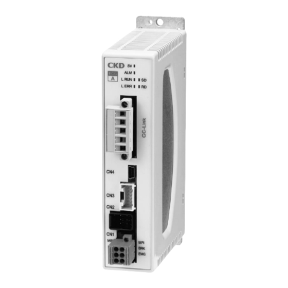
Page 10: Names Of Parts
SM-A27752/2-A 1. PRODUCT OVERVIEW 1.3 Names of Parts 1.3.1 LED Name Color Explanation Lights when receiving normal data from the PLC. L RUN Green Turns OFF at time over. Turns OFF during normal communication. Lights when CRC error occurs. L ERR Blinks when station number or communication speed changes from setting when power was turned ON. -
Page 11: Specifications
SM-A27752/2-A 1. PRODUCT OVERVIEW 1.4 Specifications 1.4.1 Communication specifications Descriptions Details Communication protocol CC-Link CC-Link version Ver.1.10 Station type Remote device station PIO mode: 1 station Half simple direct value mode: 1 station Occupied station No. Simple direct value mode: 2 stations Half direct value mode: 2 stations Full direct value mode: 4 stations PIO mode: 32 points... -
Page 12: Dimensions
SM-A27752/2-A 1. PRODUCT OVERVIEW 1.5 Dimensions ◼ Normal mounting ◼ DIN rail mounting Grounding terminal (M3 5 pan head screw) 2021-01-07... -
Page 13: Installation
SM-A27752/2-A 2. INSTALLATION 2. INSTALLATION DANGER Do not use in locations with ignitable, flammable, or explosive substances or other such dangerous substances. There may be risk of ignition, combustion, or explosion. Make sure that the product does not come in contact with water drops or oil drops. Fire or damage may result. -
Page 14: Connection
SM-A27752/2-A 2. INSTALLATION 2.1 Connection WARNING Perform the wiring with the power supply turned OFF. Touching the electrical wiring connections (bare charger) may cause electric shock. Do not touch the charger with bare hands. Doing so may cause electric shock. Read and fully understand this instruction manual before performing the electrical wiring. -
Page 15: Connection And Wiring To Cn5 (Interface Connector)
When using this product at the terminal of a network, connect a terminating resistor between “DA” and “DB.” 2.1.2 Other connections and wiring For other connection methods, refer to the instruction manual for the ECG series electric actuator controller (SM-A27751). 2021-01-07... -
Page 16: Usage
Refer to the instruction manual of the master unit manufacturer for how to install the CSP+ file. Use the latest CSP+ file to configure an appropriate network. CSP+ files are available on the website of CKD (https://www.ckd.co.jp/). <How to obtain CSP+ files>... -
Page 17: Cc-Link Device Settings
SM-A27752/2-A 3. USAGE 3.2 CC-Link device settings To connect this product as a CC-Link device, it is necessary to set the station number, station type, number of occupied stations, etc. in the PLC using a PLC development tool etc. Refer to the PLC manual for the PLC setting method. -
Page 18: Communication Format
SM-A27752/2-A 3. USAGE 3.3 Communication format 3.3.1 Data communication Type of data communication Content This type of communication is used between the master and Cyclic transmission slave on a set cycle. This type of communication is used to transmit data with an Message transmission irregular period and length. - Page 19 SM-A27752/2-A 3. USAGE ◼ Write data and read data Operate the following items. Classification Item Data to be written to the controller by the PLC Data number, data R/W selection, data request, write data (Remote output and Remote register (output)) Data to be read from the controller by the PLC Data write status, data complete, data response, read data, data (alarm) (Remote input and Remote register (input))
-
Page 20: Operation Mode
SM-A27752/2-A 3. USAGE 3.3.3 Operation mode There are 5 operation modes (CC-Link) as below. The PIO mode can be changed among the 5 types according to the setting of operation mode (PIO). Operation mode (CC- Abbreviation Name Link) PIO mode Simple direct value mode Full direct value mode Half simple direct value mode... -
Page 21: Cyclic Data
SM-A27752/2-A 3. USAGE 3.3.4 Cyclic data The format of the data to be sent and received as cyclic data is described below. Refer to “3.4 Data access” and the PLC manufacturer's manual for the communication method. ◼ Remote input/remote register (input) Set data for the PLC to read from the controller. - Page 22 Note 1: Alarms 0 to 15, in hexadecimal notation, indicate the first digit of the alarm code. For more detail, refer to “Signal name list” of “2.3.3. I/O cable wiring” in the instruction manual for the ECG series electric actuator controller (SM-A27751). For alarm codes, refer to “5.1 Alarm Indications and Countermeasures”...
- Page 23 SM-A27752/2-A 3. USAGE <Simple direct value mode (operation mode: 1)> Remote input Device No. Descriptions Value (decimal) RXn0 Point number confirmation bit 0 RXn1 Point number confirmation bit 1 Binary data RXn2 Point number confirmation bit 2 For direct value travel: 0 is set. For point travel: The travel completion point number is set.
- Page 24 SM-A27752/2-A 3. USAGE Remote input Device No. Descriptions Value (decimal) RX(n+2)4 RX(n+2)F RX(n+3)0 Reserved RX(n+3)A RX(n+3)B Remote ready flag 1: Data can be sent/received RX(n+3)C Reserved RX(n+3)F Note 1: Both point travel complete and moving may be ON (“1”) at the same time depending on the timing. Note 2: Content can be monitored even in TOOL mode when not in forced output mode.
- Page 25 SM-A27752/2-A 3. USAGE <Full direct value mode (operation mode: 2)> Remote input Device No. Descriptions Value (decimal) RXn0 Point number confirmation bit 0 RXn1 Point number confirmation bit 1 Binary data RXn2 Point number confirmation bit 2 For direct value travel: 0 is set. For point travel: The travel completion point number is set.
- Page 26 SM-A27752/2-A 3. USAGE Remote input Device No. Descriptions Value (decimal) RX(n+2)3 Zone 2 0: Outside zone, 1: Inside zone RX(n+2)4 RX(n+6)F RX(n+7)0 Reserved RX(n+7)A RX(n+7)B Remote ready flag 1: Data can be sent/received RX(n+7)C Reserved RX(n+7)F Note 1: Both point travel complete and moving may be ON (“1”) at the same time depending on the timing. Note 2: Content can be monitored even in TOOL mode when not in forced output mode.
- Page 27 SM-A27752/2-A 3. USAGE <Half simple direct value mode (operation mode: 3)> Remote input Device No. Descriptions Value (decimal) RXn0 Point number confirmation bit 0 RXn1 Point number confirmation bit 1 Binary data For direct value travel: 0 is set. RXn2 Point number confirmation bit 2 For point travel: The travel completion point number is set.
- Page 28 SM-A27752/2-A 3. USAGE Remote register (input) Value Device No. Descriptions (decimal) RWrn0 -999999 to 999999 Position (0.01 mm) (0.01 deg) Note 1 * The RWrn0 indicates the low-order 16bit, and the RWrn1 indicates the high-order 16bit. RWrn1 RWrn2 Speed (mm/s) (deg/s) Note 1 0 to 9999 RWrn3...
- Page 29 SM-A27752/2-A 3. USAGE <Half direct value mode (operation mode: 4)> Remote input Device No. Descriptions Value (decimal) RXn0 Point number confirmation bit 0 RXn1 Point number confirmation bit 1 Binary data For direct value travel: 0 is set. RXn2 Point number confirmation bit 2 For point travel: The travel completion point number is set.
- Page 30 SM-A27752/2-A 3. USAGE Remote register (input) Value Device No. Descriptions (decimal) RWrn0 -999999 to 999999 Position (0.01 mm) (0.01 deg) Note 1 * The RWrn0 indicates the low-order 16bit, and the RWrn1 indicates the high-order 16bit. RWrn1 RWrn2 Speed (mm/s) (deg/s) Note 1 0 to 9999 RWrn3...
- Page 31 SM-A27752/2-A 3. USAGE ◼ Remote output/remote register (output) Set data to write from the PLC to the controller. Refer to “3.3.6 Data number” for the items that can be selected in the data number. <PIO mode (operation mode (CC-Link): 0) Example: 64-point mode (operation mode (PIO): 0)> Remote output Value Device No.
- Page 32 SM-A27752/2-A 3. USAGE Remote register (output) Value Device No. Descriptions (decimal) RWwn0 Data written when executing data write Write data * The RWwn0 indicates the low-order 16bit, and the RWwn1 indicates the high-order 16bit. RWwn1 RWwn2 Data number Data number of data to read/write RWwn3 2021-01-07...
- Page 33 SM-A27752/2-A 3. USAGE <Simple direct value mode (operation mode (CC-Link): 1)> Remote output Value Device No. Descriptions (decimal) RYn0 Point number selection bit 0 RYn1 Point number selection bit 1 Binary data RYn2 Point number selection bit 2 0 to 63 * The RYn0 side indicates the low-order bit, and the RYn5 side RYn3 Point number selection bit 3...
- Page 34 SM-A27752/2-A 3. USAGE When starting, first confirm the PLC communication status for the alarm signal, warning • signal, and other signals, and then reference the status. If communication is not established, it will not be sent to the controller even if each bit is ON (“1”). •...
- Page 35 SM-A27752/2-A 3. USAGE <Full direct value mode (operation mode: 2)> Remote output Value Device No. Descriptions (decimal) RYn0 Point number selection bit 0 RYn1 Point number selection bit 1 Binary data RYn2 Point number selection bit 2 0 to 63 * The RYn0 side indicates the low-order bit, and the RYn5 side RYn3 Point number selection bit 3...
- Page 36 SM-A27752/2-A 3. USAGE When starting, first confirm the PLC communication status for the alarm signal, warning • signal, and other signals, and then reference the status. If communication is not established, it will not be sent to the controller even if each bit is ON (“1”). •...
- Page 37 SM-A27752/2-A 3. USAGE Remote register (output) Device No. Descriptions Value (decimal) 1: Position 2: Speed RWwnF Monitor No. 3: Current value 5: Alarm Note 1: When the PLC is powered on, this item is set to 0. The value of this item does not change unless a new value is written from the PLC.
- Page 38 SM-A27752/2-A 3. USAGE <Half simple direct value mode (operation mode(CC-Link): 3)> Remote output Value Device No. Descriptions (decimal) RYn0 Point number selection bit 0 RYn1 Point number selection bit 1 Binary data RYn2 Point number selection bit 2 0 to 63 * The RYn0 side indicates the low-order bit, and the RYn5 side RYn3 Point number selection bit 3...
- Page 39 SM-A27752/2-A 3. USAGE Remote register (output) Value Device No. Descriptions (decimal) RWwn0 -999999 to 999999 Position (0.01 mm) (0.01 deg) Note 1 * The RWwn0 indicates the low-order 16bit, and the RWwn1 indicates the high-order 16bit. RWwn1 RWwn2 RWwn3 Note 1: When the PLC is powered on, this item is set to 0. The value of this item does not change unless a new value is written from the PLC.
- Page 40 SM-A27752/2-A 3. USAGE <Half direct value mode (operation mode: 4)> Remote output Value Device No. Descriptions (decimal) RYn0 Point number selection bit 0 RYn1 Point number selection bit 1 Binary data RYn2 Point number selection bit 2 0 to 63 * The RYn0 side indicates the low-order bit, and the RYn5 side RYn3 Point number selection bit 3...
- Page 41 SM-A27752/2-A 3. USAGE Remote output Value Device No. Descriptions (decimal) RY(n+2)0 RY(n+2)F RY(n+3)0 Reserved RY(n+3)F Note 1: When the direct value travel selection is turned OFF (“0”), the point travel can be performed in the same way as the 64-point mode. •...
-
Page 42: Cyclic Data Details For Pio Mode
SM-A27752/2-A 3. USAGE 3.3.5 Cyclic data details for PIO mode ◼ 64-point mode (B064) (operation mode (PIO): 0) Remote input: Controller → PLC Device No. Descriptions Value (decimal) Point number confirmation bit 0/ RXn0 alarm confirmation bit 0 Point number confirmation bit 1/ Port numbers 0 to 63 RXn1 alarm confirmation bit 1... - Page 43 SM-A27752/2-A 3. USAGE Remote output: PLC → controller Value Device No. Descriptions (decimal) RYn0 Point number selection bit 0 RYn1 Point number selection bit 1 Binary data RYn2 Point number selection bit 2 0 to 63 * The RYn0 side indicates the low-order bit, and the RYn5 RYn3 Point number selection bit 3 side indicates the high-order bit.
- Page 44 SM-A27752/2-A 3. USAGE ◼ Simple 7-point mode (S007) (operation mode (PIO): 1) Remote input: Controller → PLC Value Device No. Descriptions (decimal) RXn0 Point number 1 travel complete 0: Incomplete, 1: Complete RXn1 Point number 2 travel complete 0: Incomplete, 1: Complete RXn2 Point number 3 travel complete 0: Incomplete, 1: Complete...
- Page 45 SM-A27752/2-A 3. USAGE Remote output: PLC → controller Value Device No. Descriptions (decimal) RYn0 Point number 1 travel start 1: Start RYn1 Point number 2 travel start 1: Start RYn2 Point number 3 travel start 1: Start RYn3 Point number 4 travel start 1: Start RYn4 Point number 5 travel start...
- Page 46 SM-A27752/2-A 3. USAGE ◼ Solenoid valve mode, double 2-position type (VW2P) (operation mode (PIO): 2) Remote input: Controller → PLC Value Device No. Descriptions (decimal) RXn0 Point number 1 travel complete 0: Incomplete, 1: Complete RXn1 Point number 2 travel complete 0: Incomplete, 1: Complete RXn2 RXn3...
- Page 47 SM-A27752/2-A 3. USAGE Remote output: PLC → controller Value Device No. Descriptions (decimal) RYn0 Solenoid valve travel command 1 1: ON RYn1 Solenoid valve travel command 2 1: ON RYn2 RYn3 RYn4 RYn5 RYn6 RYn7 RYn8 RYn9 Home position return start 1: Home position return start RYnA Servo ON...
- Page 48 SM-A27752/2-A 3. USAGE ◼ Solenoid valve mode, double 3-position type (VW3P) (operation mode (PIO): 3) Remote input: Controller → PLC Value Device No. Descriptions (decimal) RXn0 Point number 1 travel complete 0: Incomplete, 1: Complete RXn1 Point number 2 travel complete 0: Incomplete, 1: Complete RXn2 RXn3...
- Page 49 SM-A27752/2-A 3. USAGE Remote output: PLC → controller Value Device No. Descriptions (decimal) RYn0 Solenoid valve travel command 1 1: ON RYn1 Solenoid valve travel command 2 1: ON RYn2 RYn3 RYn4 RYn5 RYn6 RYn7 RYn8 RYn9 Home position return start 1: Home position return start RYnA Servo ON...
- Page 50 SM-A27752/2-A 3. USAGE ◼ Solenoid valve mode, single type (VSGL) (operation mode (PIO): 4) Remote input: Controller → PLC Value Device No. Descriptions (decimal) RXn0 Point number 1 travel complete 0: Incomplete, 1: Complete RXn1 Point number 2 travel complete 0: Incomplete, 1: Complete RXn2 RXn3...
- Page 51 SM-A27752/2-A 3. USAGE Remote output: PLC → controller Value Device No. Descriptions (decimal) RYn0 RYn1 Solenoid valve travel command 0: Travel to point 1, 1: Travel to point 2 RYn2 RYn3 RYn4 RYn5 RYn6 RYn7 RYn8 RYn9 Home position return start 1: Home position return start RYnA Servo ON...
-
Page 52: Data Number
SM-A27752/2-A 3. USAGE 3.3.6 Data number Indicates the data number used when executing data read or data write. Refer to “3.4 Data access“, “3.5.6 Data read“ and “3.5.7 Data write“ for execution of data read and data write. Data number Value Access Descriptions... - Page 53 SM-A27752/2-A 3. USAGE Data number Value Access Descriptions Unit Remarks (hexadecimal) (decimal) Note 1 Emergency stop input 0x5018 0 to 1 0: Enabled, 1: Disabled Note 4 0x5020 Pressing judgment time 0 to 9999 0x5022 Fixed current at stop 0 to 100 0x5024 Automatic servo OFF time 1 0 to 9999...
- Page 54 SM-A27752/2-A 3. USAGE Data number Value Access Descriptions Unit Remarks (hexadecimal) (decimal) Note 1 0x5402 Note 4 0 to 19 Input signal filter 0: Point zone, 0x5404 Output selection 1 Note 4 0 to 4 1: Zone 1, 2: Zone 2, 3: Travelingm, 4: Warnings 0:...
- Page 55 SM-A27752/2-A 3. USAGE Data number Value Access Descriptions Unit Remarks (hexadecimal) (decimal) Note 1 Point data for point No. n (n=0 to 63) Bit 3 to 0: Operation method 0: Positioning operation, 1: Pressing operation 1, 2: Pressing operation 2 Bit 7 to 4: Position specification method 0: Absolute...
-
Page 56: Data Access
SM-A27752/2-A 3. USAGE 3.4 Data access 3.4.1 Cyclic data Cyclic data is always exchanged between the master and slave at a set cycle. Set the data length and configuration using a PLC development tool, and assign relays and data memories. Remote output and remote register (output) will be updated when data is set (coil, bit SET, Move command, etc.). -
Page 57: Operation Time Chart
SM-A27752/2-A 3. USAGE 3.5 Operation time chart 3.5.1 Servo ON WARNING Keep safety in mind. When turning servo OFF during operation, operation may continue with the inertia of the workpiece. CAUTION When turning the servo ON, check that the actuator operates safely. The actuator could start operating once the servo is turned ON, which could cause injury or damage the workpiece. -
Page 58: From Power-On To Home Position Return
SM-A27752/2-A 3. USAGE 3.5.2 From power-on to home position return The diagram below shows the timing of home position return completion from the beginning of the return after the power is turned on. Horizontal axis: Time Control power Power supply Motor power Green Controller display... -
Page 59: Home Position Return Operation
SM-A27752/2-A 3. USAGE 3.5.3 Home position return operation When a home position return operation is executed, a home position return operation is performed. The position at which home position return operation completes becomes the home position (0 mm). Position after Position after 原点復帰後... -
Page 60: Positioning Operation
SM-A27752/2-A 3. USAGE 3.5.4 Positioning operation ◼ Point operation <Designating a stop during travel> Horizontal axis: Time Point travel start Remote Stop output (Negative logic) The traveling Point number point number is designated selection in binary code. Displacement 変位 Point 7 Displacement Point 3 Point 1... - Page 61 SM-A27752/2-A 3. USAGE <Designating a pause during travel> Horizontal axis: Time Point travel start Pause Remote (Negative output logic) The traveling Point point number is designated number in binary code. selection Displacement Point 7 Displacement Point 3 Point 1 Note 2 Point travel complete Remote...
- Page 62 SM-A27752/2-A 3. USAGE ◼ Direct value operation <Simple direct value mode and Half simple direct value mode> Check that the point data for the point number to be specified by remote output is set. Set the position and point number in the remote output and remote register (output). Set Direct value travel selection to ON.
- Page 63 SM-A27752/2-A 3. USAGE <Full direct value mode and Half direct value> After setting the position, speed, and other point data in the remote register (output), turn the travel start bit ON. Horizontal axis: Time Point travel start Remote output Direct value travel Remote register selection...
- Page 64 SM-A27752/2-A 3. USAGE <Direct value travel selection and direct travel status> Turn ON the direct value travel selection. When the direct value travel starts, the direct value travel status is turned ON, and it stays ON until the next point travel starts. (It remains ON even when the servo OFF.) Horizontal axis: Time 横軸:時間...
-
Page 65: Monitor
SM-A27752/2-A 3. USAGE 3.5.5 Monitor After setting the monitor number, turn monitor request ON. Monitor No. Data output to monitor value (hexadecimal) (decimal) Position (0.01 mm) (0.01 deg) 0x0001 −999999 to 999999 Speed (mm/s) (deg/s) 0x0002 0 to 9999 Current (%) 0x0003 0 to 100 0x0005... -
Page 66: Data Read
SM-A27752/2-A 3. USAGE 3.5.6 Data read After setting the data number and data R/W selection, turn data request ON. Confirm that data complete is ON, and then turn data request OFF. • Do not change ON/OFF of the data R/W selection or switch the PLC mode / TOOL mode •... -
Page 67: Data Write
SM-A27752/2-A 3. USAGE 3.5.7 Data write After setting the data number, write data, and data R/W selection, turn data request ON. • Confirm that data complete is ON, and then turn data request OFF. Do not change ON/OFF of the data R/W selection or switch the PLC mode / TOOL mode •... -
Page 68: Warranty Provisions
If the product specified herein fails for reasons attributable to CKD within the warranty period specified below, CKD will promptly provide a replacement for the faulty product or a part thereof or repair the faulty product at one of CKD's facilities free of charge.
Need help?
Do you have a question about the ECG Series and is the answer not in the manual?
Questions and answers