Table of Contents
Advertisement
Quick Links
Electric Actuator
ECR (Controller)
CC-Link Specifications
INSTRUCTION MANUAL
SM-A10617-A
Instruction Manual
• Be sure to read this instruction manual before using the product.
• Pay especially close attention to the safety-related information contained within.
• Keep this instruction manual in a safe place so that it is readily available when needed.
CKD Corporation
Advertisement
Table of Contents

Related Manuals for CKD ECR Series


Summary of Contents for CKD ECR Series
- Page 1 • Be sure to read this instruction manual before using the product. • Pay especially close attention to the safety-related information contained within. • Keep this instruction manual in a safe place so that it is readily available when needed. CKD Corporation...
- Page 2 PREFACE PREFACE Thank you for purchasing this CKD "ECR" controller for electric actuators. In order for this product to be used to its fullest potential, this instruction manual describes basic topics such as how to mount and use it. Read this manual thoroughly prior to use.
- Page 3 Therefore, confirm that the safety of the equipment's mechanisms and the system that runs the electrical controls can be ensured. It is important to select, use, handle and maintain CKD products appropriately to ensure their safe usage. Be sure to observe the warnings and precautions listed in this instruction manual to ensure equipment safety.
- Page 4 SM-A10617-A SAFETY INFORMATION Product precautions DANGER Do not use this product for the following applications. • Medical devices involved in maintaining or managing human life or health • Mechanisms or machines meant to transfer or transport people • Important security parts in machines WARNING Use this product in accordance with specifications.
-
Page 5: Table Of Contents
SM-A10617-A CONTENTS CONTENTS PRODUCT OVERVIEW ..................... 1 Configuration of product ..................1 System Overview ....................2 Specifications ...................... 3 1.3.1 Communication specifications ..............3 1.3.2 Communication status display ..............4 INSTALLATION ......................5 Connection ......................6 USAGE ........................7 Data communication ................... 7 CSP+ files ...................... -
Page 6: Product Overview
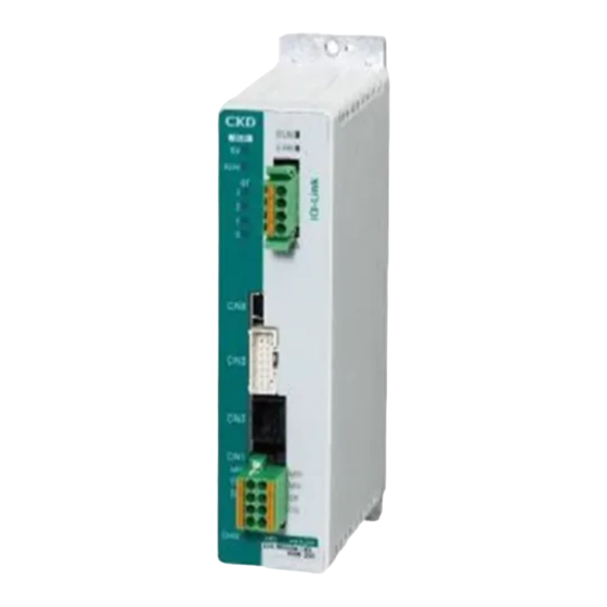
SM-A10617-A 1. PRODUCT OVERVIEW 1. PRODUCT OVERVIEW CC-Link is a registered trademark of Mitsubishi Electric Corporation. 1.1 Configuration of product Name Qty. Controller body Connector for power supply: DFMC1,5/4-STF-3,5 (PHOENIX CONTACT) Accessory Communication connector (CC-Link): MSTB2,5/5-STF-5,08ABGYAU (PHOENIX CONTACT) -
Page 7: System Overview
Encoder cable Motor cable Applicable actuators EBS-M Series EBR-M Series FLSH Series FLCR Series FGRC Series System components that can be purchased from CKD are listed below. Descriptions Name Product name、Model No. Controller ECR Series Normal configuration Actuator EBS-M/EBR-M/FLSH/FLCR/FGRC Series... -
Page 8: Specifications
SM-A10617-A 1. PRODUCT OVERVIEW 1.3 Specifications 1.3.1 Communication specifications Descriptions Details Communication protocol CC-Link CC-Link version Ver.1.10 Station type Remote device station PIO mode: 1 station Occupied station No. Simple direct value mode: 2 stations Full direct value mode: 4 stations PIO mode: 32 points Remote input Simple direct value mode: 64 points... -
Page 9: Communication Status Display
SM-A10617-A 1. PRODUCT OVERVIEW 1.3.2 Communication status display SD (green lamp) Blinks when transmitting data. RD (green lamp) Lights when receiving data. L RUN (green lamp) Lights when receiving normal data from the PLC. Turns OFF at time over. ... -
Page 10: Installation
SM-A10617-A 2. INSTALLATION 2. INSTALLATION DANGER Do not use in locations with ignitable, flammable, or explosive substances or other such dangerous substances. There may be risk of ignition, combustion, or explosion. Make sure that the product does not come in contact with water drops or oil drops. Fire or damage may result. -
Page 11: Connection
SM-A10617-A 2. INSTALLATION 2.1 Connection This instruction manual discusses CN5: Interface Connector only. For other connection methods, refer to the instruction manual (SM-A10615) for the electric actuator (controller). Pin No. Signal *1 *2 *1: SLD and FG are internally connected. *2: Make sure to ground prior to use. -
Page 12: Usage
SM-A10617-A 3. USAGE 3. USAGE 3.1 Data communication Type of data communication Content This type of communication is used between the master and slave Cyclic transmission on a set cycle. This type of communication is used to transmit data with an Message transmission irregular period and length. -
Page 13: Csp+ Files
CSP+ files contain information required to launch, operate, and maintain CC-Link components. CSP+ files can be used for easier configuration of components from the PLC development tool. Import these files into the PLC development tool if required. See the CKD website. https://www.ckd.co.jp/ [CSP+ file] 0x0104_ECR-MNNN3B-CL_V10000_ja_20.zip... -
Page 14: Cc-Link Device Settings
SM-A10617-A 3. USAGE 3.3 CC-Link device settings Normally, a PLC development tool or the like must be used to set the product's station number, type of station, occupied station No., and other settings in the PLC. For information on how to set the PLC, refer to the PLC manual. ... -
Page 15: Communication Format
SM-A10617-A 3. USAGE 3.4 Communication format 3.4.1 Cyclic data Remote input/remote register (input) Set data for the PLC to read from the controller. [PIO mode (operation mode: 0) [Example] 64-point mode (operation mode (PIO): 0)] Remote input Value Device No. Descriptions (decimal) Point number confirmation bit 0/... - Page 16 SM-A10617-A 3. USAGE Remote register (input) Value Device No. Descriptions (decimal) RWrn0 Note 1 RWrn1 Note 1 RWrn2 Note 1 RWrn3 Note 1 Note1: There is no function assignment in PIO mode.
- Page 17 SM-A10617-A 3. USAGE [Simple direct value mode (operation mode: 1)] Remote input Value Device No. Descriptions (decimal) RXn0 Point number confirmation bit 0 RXn1 Point number confirmation bit 1 RXn2 Point number confirmation bit 2 Binary data [During direct value travel] RXn3 Point number confirmation bit 3 RXn4...
- Page 18 SM-A10617-A 3. USAGE Remote input Value Device No. Descriptions (decimal) RX(n+3)0 Reserved RX(n+3)9 RX(n+3)A Error status flag 1: Error detected RX(n+3)B Remote ready flag 1: Data can be sent/received RX(n+3)C Reserved RX(n+3)F Remote register (input) Value Device No. Descriptions (decimal) RWrn0 Position (0.01 mm) (0.01 deg) -999999 to 999999...
- Page 19 SM-A10617-A 3. USAGE [Full direct value mode (operation mode: 2)] Remote input Value Device No. Descriptions (decimal) RXn0 Point number confirmation bit 0 RXn1 Point number confirmation bit 1 RXn2 Point number confirmation bit 2 Binary data [During direct value travel] RXn3 Point number confirmation bit 3 RXn4...
- Page 20 SM-A10617-A 3. USAGE Remote input Value Device No. Descriptions (decimal) RX(n+7)0 Reserved RX(n+7)9 RX(n+7)A Error status flag 1: Error detected RX(n+7)B Remote ready flag 1: Data can be sent/received RX(n+7)C Reserved RX(n+7)F Remote register (input) Value Device No. Descriptions (decimal) RWrn0 Position (0.01 mm) (0.01 deg) -999999 to 999999...
- Page 21 SM-A10617-A 3. USAGE Remote output/remote register (output) Set data to write from the PLC to the controller. [PIO mode (operation mode: 0) [Example] 64-point mode (operation mode (PIO): 0)] Remote output Value Device No. Descriptions (decimal) RYn0 Point number selection bit 0 RYn1 Point number selection bit 1 RYn2...
- Page 22 SM-A10617-A 3. USAGE [Simple direct value mode (operation mode: 1)] Remote output Value Device No. Descriptions (decimal) RYn0 Point number selection bit 0 RYn1 Point number selection bit 1 RYn2 Point number selection bit 2 RYn3 Point number selection bit 3 Binary data RYn4 Point number selection bit 4...
- Page 23 SM-A10617-A 3. USAGE Remote output Value Device No. Descriptions (decimal) RY(n+3)0 Reserved RY(n+3)9 RY(n+3)A Error reset request flag 1: Reset RY(n+3)B Reserved RY(n+3)F Remote register (output) Value Device No. Descriptions (decimal) RWwn0 Position (0.01 mm) (0.01 deg) -999999 to 999999 RWwn1 RWwn2 Data written when executing data...
- Page 24 SM-A10617-A 3. USAGE [Full direct value mode (operation mode: 2)] Remote output Value Device No. Descriptions (decimal) RYn0 Point number selection bit 0 RYn1 Point number selection bit 1 RYn2 Point number selection bit 2 RYn3 Point number selection bit 3 Binary data RYn4 Point number selection bit 4...
- Page 25 SM-A10617-A 3. USAGE Remote output Value Device No. Descriptions (decimal) RY(n+7)0 Reserved RY(n+7)9 RY(n+7)A Error reset request flag 1: Reset RY(n+7)B Reserved RY(n+7)F Remote register (output) Value Device No. Descriptions (decimal) RWwn0 Position (0.01 mm) (0.01 deg) -999999 to 999999 RWwn1 Positioning width (0.01 mm) (0.01 0 to 999 (when setting = 0, use...
-
Page 26: Cyclic Data Details For Pio Mode
SM-A10617-A 3. USAGE 3.4.2 Cyclic data details for PIO mode 64-point mode (B064) (operation mode (PIO): 0) Remote input: Controller → PLC Value Device No. Descriptions (decimal) Point number confirmation bit 0/ RXn0 alarm confirmation bit 0 Point number confirmation bit 1/ Port numbers 0 to 63 RXn1 alarm confirmation bit 1... - Page 27 SM-A10617-A 3. USAGE 128-point mode (B128) (operation mode (PIO): 1) Remote input: Controller → PLC Value Device No. Descriptions (decimal) Point number confirmation bit 0/ RXn0 alarm confirmation bit 0 Point number confirmation bit 1/ RXn1 alarm confirmation bit 1 Port numbers 0 to 127 Alarms 0 to 15...
- Page 28 SM-A10617-A 3. USAGE 256-point mode (B256) (operation mode (PIO): 2) Remote input: Controller → PLC Value Device No. Descriptions (decimal) Point number confirmation bit 0/ RXn0 alarm confirmation bit 0 Point number confirmation bit 1/ RXn1 alarm confirmation bit 1 Port numbers 0 to 255 Point number confirmation bit 2/ Alarms...
- Page 29 SM-A10617-A 3. USAGE 512-point mode (B512) (operation mode (PIO): 3) Remote input: Controller → PLC Value Device No. Descriptions (decimal) Point number confirmation bit 0/ RXn0 alarm confirmation bit 0 Point number confirmation bit 1/ RXn1 alarm confirmation bit 1 Point number confirmation bit 2/ Port numbers 0 to 511 RXn2...
- Page 30 SM-A10617-A 3. USAGE Teaching 64-point mode (T064) (operation mode (PIO): 4) Remote input: Controller → PLC Value Device No. Descriptions (decimal) Point number confirmation bit 0/ RXn0 alarm confirmation bit 0 Point number confirmation bit 1/ RXn1 Port numbers 0 to 63 alarm confirmation bit 1 Alarms 0 to 15...
- Page 31 SM-A10617-A 3. USAGE Simple 7-point mode (S007) (operation mode (PIO): 5) Remote input: Controller → PLC Value Device No. Descriptions (decimal) RXn0 Point number 1 travel complete 0: Incomplete, 1: Complete RXn1 Point number 2 travel complete 0: Incomplete, 1: Complete RXn2 Point number 3 travel complete 0: Incomplete, 1: Complete...
- Page 32 SM-A10617-A 3. USAGE Solenoid valve mode, double 2-position type (VW2P) (operation mode (PIO): 6) Remote input: Controller → PLC Value Device No. Descriptions (decimal) RXn0 Point number 1 travel complete 0: Incomplete, 1: Complete RXn1 Point number 2 travel complete 0: Incomplete, 1: Complete RXn2 RXn3...
- Page 33 SM-A10617-A 3. USAGE Solenoid valve mode, double 3-position type (VW3P) (operation mode (PIO): 7) Remote input: Controller → PLC Value Device No. Descriptions (decimal) RXn0 Point number 1 travel complete 0: Incomplete, 1: Complete RXn1 Point number 2 travel complete 0: Incomplete, 1: Complete RXn2 RXn3...
- Page 34 SM-A10617-A 3. USAGE Solenoid valve mode, single type (VSGL) (operation mode (PIO): 8) Remote input: Controller → PLC Value Device No. Descriptions (decimal) RXn0 Point number 1 travel complete 0: Incomplete, 1: Complete RXn1 Point number 2 travel complete 0: Incomplete, 1: Complete RXn2 RXn3...
-
Page 35: Data Number
SM-A10617-A 3. USAGE 3.4.3 Data number Indicates the data number used when executing data read or data write. Data number Value Access Descriptions Unit Remarks (hexadecimal) (decimal) n: Set the bit as follows. Bit 0: 1 = Parameter data Initialize all 0x999n Bit 1: (Not in use) 0x0505... - Page 36 SM-A10617-A 3. USAGE Data number Value Access Descriptions Unit Remarks (hexadecimal) (decimal) Read data Bit 15 to 0: Alarm code Bit 23 to 16: Month Bit 31 to 24: Year Alarm code 0x4000 Alarm log Data (alarm) Alarm date and time Bit 7 to 0: Hour Bit 15 to 8: Day Bit 23 to 16: Second...
- Page 37 SM-A10617-A 3. USAGE Data number Value Access Descriptions Unit Remarks (hexadecimal) (decimal) 0x8000 0.01 mm Point data for point No. n Position -999999 to 999999 + 32*n 0.01deg (n=0 to 511) 0x8002 0.01 mm Point data for point No. n Positioning width 0 to 999 + 32*n...
-
Page 38: Data Access
SM-A10617-A 3. USAGE 3.5 Data access Cyclic data Cyclic data is always exchanged between the master and slave at a set cycle. Normally, the PLC development tool is used to set the data length and configuration, and to assign relays and data memory. Remote output and remote register (output) will be updated when data is set (coil, bit SET, Move command, etc.). -
Page 39: Operation Mode
SM-A10617-A 3. USAGE 3.6 Operation mode The following three types of operation modes (CC-Link) are available. The PIO mode can be changed to the following nine types of settings, based on the operation mode (PIO) setting. PIO mode (abbreviation: PIO) (operation mode (CC-Link): 0) This mode performs control in accordance with conventional signal I/O. -
Page 40: Operation Time Chart
SM-A10617-A 3. USAGE 3.7 Operation time chart 3.7.1 Servo ON If servo OFF occurs during operation, deceleration is stopped and the motor enters a de-energized state. During servo OFF, operation preparation complete output turns OFF, and if there are brakes, they are locked. -
Page 41: When Powered On
SM-A10617-A 3. USAGE 3.7.2 When powered on As in the figure below, the time chart covers home position return start after power ON to home position return complete. Horizontal axis: Time 横軸:時間 制御 Control power 電源 電源 Power supply モータ Motor power 電源... -
Page 42: Home Position Return Operation
SM-A10617-A 3. USAGE 3.7.3 Home position return operation When a home position return operation is executed, a home position return operation is performed. The position at which home position return operation completes becomes the home position (0 mm). Position after Position after 原点復帰後... -
Page 43: Positioning Operation
SM-A10617-A 3. USAGE 3.7.4 Positioning operation PIO mode (operation mode: 0) Designating a stop during travel 横軸:時間 Horizontal axis: Time 移動 Point travel 開始 start 指令 停止 Remote Stop output (out) (b-contact) (b接点) The traveling point number is ポイント Point number designated in... - Page 44 SM-A10617-A 3. USAGE Designating a pause during travel 横軸:時間 Horizontal axis: Time 移動 Point travel 開始 start 指令 一時 Pause 停止 (out) (b-contact) (b接点) The traveling ポイント Point point number is number 番号 designated in binary code. Displacement 変 位 ポイント7 Point 7 Displacement...
- Page 45 SM-A10617-A 3. USAGE Simple direct value mode (operation mode: 1) With point data set for the point number designated by remote output, set the position and point number in remote output and the remote register (output), and then turn the point travel start bit ON. *1: Leave an interval of at least 10 ms for point travel start ON after setting the position and point number.
- Page 46 SM-A10617-A 3. USAGE ・Data set in the point number in the simple direct value mode figure. (3) Point number with point data set to travel position 2 (4) Point number with point data set to travel position 3 (using (3) is also acceptable if the speed, acceleration, etc.
- Page 47 SM-A10617-A 3. USAGE Full direct value mode (operation mode: 2) After setting the position, speed, and other point data in the remote register (output), turn the travel start bit ON. *1: Leave an interval of at least 10 ms for point travel start ON after setting the point data. *2: Note that the previous point travel complete will still be ON until an instruction is received, even after point travel start ON.
-
Page 48: Monitor
SM-A10617-A 3. USAGE 3.7.5 Monitor After setting the monitor number, turn monitor request ON. Monitor No. Data output to monitor value (hexadecimal) (decimal) Position (0.01 mm) (0.01 deg) 0x0001 -999999 to 999999 Speed (mm/s) (deg/s) 0x0002 0 to 9999 Current (%) 0x0003 0 to 100 0x0005... -
Page 49: Data Read
SM-A10617-A 3. USAGE 3.7.6 Data read After setting the data number and data R/W selection, turn data request ON. Confirm that data complete is ON, and then turn data request OFF. Data response Content RX(n+1)3 RX(n+1)2 RX(n+1)1 RX(n+1)0 Normal Data number error... -
Page 50: Data Write
SM-A10617-A 3. USAGE 3.7.7 Data write After setting the data number, write data, and data R/W selection, turn data request ON. Confirm that data complete is ON, and then turn data request OFF. Data response Content RX(n+1)3 RX(n+1)2 RX(n+1)1 RX(n+1)0 Normal Data number error Failure... -
Page 51: Warranty Provisions
If the product specified herein fails for reasons attributable to CKD within the warranty period specified below, CKD will promptly provide a replacement for the faulty product or a part thereof or repair the faulty product at one of CKD’s facilities free of charge.
Need help?
Do you have a question about the ECR Series and is the answer not in the manual?
Questions and answers