Table of Contents

Related Manuals for CKD EJSG Series


Summary of Contents for CKD EJSG Series
- Page 1 EJSG Series Electric Actuator Slider Type INSTRUCTION MANUAL Read this Instruction Manual before using the product. In particular, read the safety notes carefully. Keep this Instruction Manual safe for use at any time. 2022-08-17 SM-A70436-A...
-
Page 2: Preface
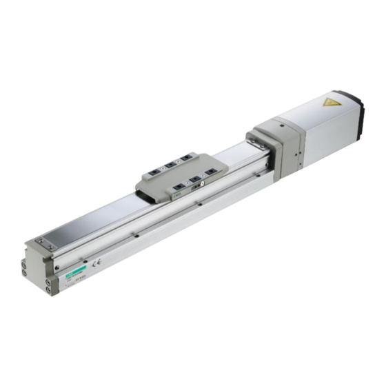
PREFACE Thank you for purchasing CKD's "EJSG Series" electric actuator. The EJSG series (slider type) are rod-less electric actuators designed for conveyance. A wide guide integrated into the body provides high rigidity while allowing for compact size. This Instruction Manual describes basic matters related to the operation of this product in order to fully demonstrate its performance. -
Page 3: Safety Information
SAFETY INFORMATION When designing and manufacturing any device incorporating the product, the manufacturer has an obligation to ensure that the device is safe. To that end, make sure that the safety of the machine mechanism of the device and the electric system that controls such mechanism is ensured. - Page 4 < Warning symbol type > A general-purpose mark A mark that prohibits touching indicating prohibited (not the equipment. allowed) actions. A general-purpose mark A mark that prohibits the act of indicating the danger such as putting a finger. electric shock and burn. A mark indicating the danger A general-purpose mark that occurs when an automatic...
-
Page 5: Precautions On Product Use
Precautions on Product Use DANGER Do not use this product for the following applications. Medical equipment pertaining to sustainment and management of human life and body Mechanism and mechanical device for transferring and transporting people Critical parts for securing safety in a mechanical device WARNING Never modify or implement additional processing to the product. -
Page 6: Table Of Contents
CONTENTS PREFACE ......................2 SAFETY INFORMATION ..................3 Precautions on Product Use ..................... 5 CONTENTS ......................6 1. PRODUCT OVERVIEW ..................7 System Structure ....................... 7 Instruction Manuals Related to This Product ..............9 Part Name ......................... 10 Model Number Indication ....................11 2. -
Page 7: Product Overview
Motor cable Encoder cable Connectable actuators EJSG series The above diagram is a configuration diagram for the parallel I/O design. For other interface specifications, refer to the instruction manual for each interface specification. ⚫ Connect this product to an ECG-A Series controller. It does not work when connected to other controllers such as ECG-B and ECR Series controllers. - Page 8 Of the items in the system configuration, the following can be purchased from us. Component Product name/Model no. This product Actuator EJSG Series EA-CBLM4-□□□(Standard・FP1・C Series) EA-CBLM3-□□□(P4 Series) Motor cable EA-CBLM5-□□□(G Series) Accessories EA-CBLE4-□□□(Standard Series) Encoder cable EA-CBLE3-□□□(P4 Series) EA-CBLE5-□□□(G Series)
-
Page 9: Instruction Manuals Related To This Product
This Product This Instruction Manual is “SM-A70436-A”. The instruction manuals related to this product are as follows. Controller for Electric Actuators Electric Actuator SM-A70436-A (This Instruction Manual) SM-A27751 EJSG series ECG Series Parallel I/O specifications SM-A27752 ECG Series CC-Link specifications SM-A40831... -
Page 10: Part Name
Part Name EJSG series Steel belt Connection Non-motor Motor side Motor unit plate Slider side Slider body 2022-08-17 SM-A70436-A... -
Page 11: Model Number Indication
Model Number Indication EJSG series EJSG 06 0300 Body size Screw lead Brake Fitting Working environment option 6 mm Body None None Blank width 44 Blank Standard 12 mm Compatible with rechargeable battery Motor mounting direction Encoder manufacturing processes Battery-less absolute... - Page 12 EJSG 05 0300 Body size Screw lead Brake Fitting Working environment option Body 5 mm None None Blank width 54 Blank Standard 10 mm Compatible with 20 mm rechargeable battery manufacturing processes Motor mounting direction Encoder Compatible with Battery-less absolute Straight mounting food manufacturing encoder...
- Page 13 EJSG 05 0300 Body size Screw lead Fitting Working environment Brake option Body 5 mm None None Blank Width Blank Standard 82 mm 10 mm Compatible with 20 mm rechargeable battery manufacturing processes Motor mounting direction Encoder Compatible with Battery-less absolute Straight mounting food manufacturing encoder...
- Page 14 Motor cable (fixed/movable) ◼ Motor cable model number explanation (ECG-A Series) EA-CBLM Cable length Cable specifications Cable type EJSG Standard Fixed cable EJSG-FP1 Movable cable EJSG-C 10 m EJSG-P4 EJSG-G ◼ Motor cable dimensions (ECG-A Series) ・ EA-CBLM4 : For EJSG Standard, EJSG-FP1, EJSG-C Actuator side Controller side Fixed : φ...
- Page 15 Encoder cable (fixed/movable) ◼ Encoder cable model number explanation (ECG-A Series) EA-CBLE Cable length Cable specifications Cable type EJSG Standard Fixed cable EJSG-FP1 Movable cable EJSG-C 10 m EJSG-P4 EJSG-G ◼ Encoder cable dimensions (ECG-A Series) ・ EA-CBLM4 : For EJSG Standard, EJSG-FP1, EJSG-C Actuator side Controller side Fixed : φ...
-
Page 16: Installation
INSTALLATION DANGER Do not use the product in a place where dangerous substances such as ignitable, inflammable, or explosive materials are present. A fire, ignition, or explosion may occur. Do not work with wet hands. Doing so may cause electric shock. Prevent water and oil from splashing onto the product. - Page 17 WARNING Do not install the product to a combustible material. Installing it on combustible materials or near combustible materials may cause a fire. Do not place heavy objects on cables or pinch them. If the cable sheath is torn or excessive stress is applied, it may cause poor continuity or deterioration of insulation.
- Page 18 WARNING Design a safety circuit or safety device to prevent damage to the device or an accident resulting in injury or death if the machine stops in the event of a system malfunction such as an emergency stop or power failure. Check the wiring of the product in this Instruction Manual or the related instruction manual to ensure that there are no wiring errors or loose connectors.
- Page 19 CAUTION Do not use the product in an environment where a strong magnetic field occurs. A malfunction may occur. Do not perform a withstand voltage test or an insulation resistance test in a device with the product installed. Due to the circuit design, the product may be damaged if a withstand voltage test or an insulation resistance test is performed on the device with the product installed.
- Page 20 CAUTION When installing an external stopper or a holding mechanism (such as a brake), arrange it so as not to affect the detection of the home position. Unintended position may be recognized as the home position due to the influence of external stopper or holding mechanism when returning to the home position.
- Page 21 CAUTION When using positioning holes, make sure to use pins having the size that does not require press-fitting. Press fitting pins may cause damage or distortion in the guide section, resulting in reduced accuracy. The recommended tolerance of the pin is JIS tolerance of 6 µm or less.
-
Page 22: Installation Environment
Installation Environment Before storing or using the product, check the ambient temperature and atmosphere specified in the product specifications. Use the product at an ambient temperature between 10°C and 40°C. Ventilate if heat can become trapped. Use the product at an ambient humidity between 35% and 80% RH. Do not use the product in a place where condensation occurs. -
Page 23: Unpacking
Unpacking CAUTION Heavy products shall not be carried by a worker alone. Never ride on the packaging. Do not place heavy items or items with concentrated loads that may deform the packaging. Do not apply excessive force to any part of the product. Pay sufficient attention to avoid an impact such as dropping during transportation and handling. -
Page 24: Installing
Installing Precision processing finishing has been performed for the base and table mounting surfaces so that this product will obtain highly accurate linear movement. The flatness of the mounting surface of a system has been finished highly accurately by grinding processing, so stable high accuracy can be obtained (Recommended flatness: 0.05 mm/200 mm or less). - Page 25 EJSG series CAUTION Do not allow excessive shock or moment to act on the slider. A malfunction or damage may occur. The flatness of the workpiece mounting surface should be 0.05 mm or less. Do not apply twisting or bending force to the product.
-
Page 26: Usage
USAGE DANGER Do not enter the operating range while the actuator can operate. An injury may occur. Do not work with wet hands. Doing so may cause electric shock. WARNING Do not climb on the product or put things on it. ... - Page 27 CAUTION When the controller and actuator are connected with a cable, do not move the actuator moving part by external force except for manual operation. A malfunction or damage may occur due to regenerative currents. Do not apply external force to the actuator during the home position return operation.
-
Page 28: Maintenance And Inspection
MAINTENANCE AND INSPECTION WARNING Do not disassemble or modify products not specified in this Instruction Manual. In addition to causing injuries, accidents, malfunctions, or failures, it may not meet the specifications such as this Instruction Manual. Do not attach or detach wiring or connectors while the power is turned ... -
Page 29: Periodic Inspection
Note 4 tears on the timing belt. Check that there are no vibrations or abnormal Noise If there is any abnormality, contact your nearest CKD sounds while the product inspection sales office or distributor. is stopped or operated. Check the power system and use the product within the... - Page 30 THK Co., Ltd. EJSG-FP series THK Co., Ltd. EJSG-C series * Contact CKD for the grease for the EJSG-P4 series. ◼ Nozzle tip shape For the recommended tip shape of a nozzle used for grease application, refer to the following figure.
- Page 31 Lubrication procedure The lubrication procedure for the EJSG series is as follows: Wipe off grease and dirt. Wipe off old grease and dirt with a clean waste cloth. Use caution to prevent foreign matter from remaining in the moving parts.
- Page 32 Replacement and adjustment procedures for the steel belt The procedures for replacing and adjusting the steel belt in the EJSG series are as follows: Remove the resin cover. Loosen the four bolts on the slider section with a hex key for M3 (across flats: 2 mm) and then remove the resin cover.
- Page 33 Replace the steel belt. Place a new steel belt and temporarily fasten the holding brackets and bolts removed in Step 2. Temporarily tighten the bolts to the extent that the steel belt can slide. Secure the steel belt. Align the steel belt with the shaft center and tighten the two bolts on the non-motor side with the specified tightening torque (0.4 N·m).
- Page 34 Replacement and adjustment procedures for the timing belt This section describes the procedures for replacing and adjusting the timing belt when the motor mounting direction is "R: Right mounting," "D: Bottom mounting," or "L: Left mounting." ⚫ Be careful not to lose the removed parts such as bolts because they will be required again for assembly.
- Page 35 ◼ Replacing the timing belt Bolt Tool Actuator Hexagon socket head bolt (M3 x Hex key for M3 EJSG-04R/D/L 16L) x 4 pieces (across flats: 2.5 mm) EJSG-05R/D/L Hexagon socket head bolt (M4 x Hex key for M4 (across flats: 3 mm) EJSG-08R/D/L 18L) x 4 pieces Timing belt model number...
- Page 36 ◼ Adjusting the tension on the timing belt Bolt Tool Actuator EJSG-04R/D/L Hexagon socket head bolt (M3 x Hex key for M3 16L) x 4 pieces (across flats: 2.5 mm) EJSG-05R/D/L Hexagon socket head bolt (M4 x Hex key for M4 (across flats: 3 mm) EJSG-08R/D/L 18L) x 4 pieces Put a cable tie or a cord around the base of the...
- Page 37 ◼ Attaching the belt cover Bolt Tool Hexagon socket head bolt (M3 x 30L) x 4 Hex key for M3 (across flats: 2.5 mm) pieces Attach the belt cover. Tighten four bolts with the specified tightening torque (0.3 N·m) and attach the belt cover.
-
Page 38: Precautions On Product Disposal
Precautions on Product Disposal CAUTION When disposing of the product, comply with “laws pertaining to disposal of wastes and cleaning” and have an industrial waste disposal company dispose of the product. 2022-08-17 SM-A70436-A... -
Page 39: Troubleshooting
It requires repair. when the power The product is failure or Contact your nearest CKD sales office or supply is turned damaged. distributor. The power supply is faulty. Repair or replace the power supply. - Page 40 Problem Cause Action It is colliding with the workpiece. Check the assembly and setting status. Product does not Recheck the environment conditions and the operate as Internal resistance of product conditions of use. intended with has increased. Check the usage period (operating distance). PLC signal.
- Page 41 Check the “acceleration” in the point data. Product cannot Setting of acceleration or speed reach target takt is not correct. Check the “speed” in the point data. time. If you have any other questions or concerns, contact your nearest CKD sales office or distributor. 2022-08-17 SM-A70436-A...
- Page 42 Items to Check When a Problem Occurs Item What to check Check the light status on the controller. Communication status When the control power is At the time of Lit green servo ON At normal operation At the time of Blinking green (lit once per servo OFF second)
-
Page 43: Warranty Provisions
If the product specified herein fails for reasons attributable to CKD within the warranty period specified below, CKD will promptly provide a replacement for the faulty product or a part thereof or repair the faulty product at one of CKD’s facilities free of charge. However, the following failures are excluded from this warranty: ... -
Page 44: Reference Information
Reference Information Specifications EJSG series <EJSG-04 Series> Item Description Motor mount type Motor straight mounting type Folded motor mounting type Motor Stepping motor Encoder type Battery-less absolute encoder, incremental encoder Rolled ball screw (Φ10) Drive method □35 Motor size Stroke length... - Page 45 Item Description 10 MΩ, 500 VDC Insulation resistance Withstand voltage 500 VAC, 1 minute Operating ambient temperature 10 to 40°C (no freezing) Operating ambient humidity 35 to 80% RH (no condensation) Storage ambient temperature -10 to 50°C (no freezing) Storage ambient humidity 35 to 80% RH (no condensation) Atmosphere No corrosive gas, explosive gas, or dust...
- Page 46 <EBS-05G Series> Item Description Motor mount type Motor straight mounting type Folded motor mounting type Motor Stepping motor Encoder type Battery-less absolute encoder, incremental encoder Rolled ball screw (Φ12) Drive method □42 Motor size Stroke length 50 to 800 Screw lead Max.
- Page 47 <EBS-08G Series> Item Description Motor mount type Motor straight mounting type Folded motor mounting type Motor Stepping motor Encoder type Battery-less absolute encoder, incremental encoder Rolled ball screw (Φ15) Drive method □56 Motor size Stroke length 50 to 1100 Screw lead Max.
-
Page 48: Index
Index B M Belt cover ..............34 Motor cable ..............14 E N Encoder cable ............15 Nozzle ................ 30 F O Flatness ..............24, 25 Operating speed range ..........44 G R Grease ..............29, 30 Repeatability ............... 44 L... -
Page 49: Glossary
Glossary CAT5e EDS file A standard for network cables, also called category Abbreviation for Electronic Data Sheet file. It 5e or category 5 enhanced. The communication contains information to help start up, operate, and speed has been improved from the conventional maintain EtherNet/IP-compatible devices. - Page 50 Input signal Alarm code It indicates the bit-wise data to be written from the When an error is detected, it is output from the host device (PLC, etc.) to the controller in EtherCAT controller to inform you of the error. You can check communication.
- Page 51 Portable mass Grease It indicates the maximum mass that the actuator It is applied to bearings, bearings, etc., to reduce can transfer. friction and smooth the operation of the machine. Because the performance cannot be demonstrated due to deterioration of grease or adhesion of foreign Allowable thrust load material, periodic maintenance is required.
- Page 52 Static allowable moment Soft limit Limit value of the load moment that can be applied It indicates the limit of the operating range set in the to the slider when the actuator is stationary. How to controller. apply each moment in the slider type is as follows. Dynamic brake ...
- Page 53 Half-duplex communication Rolled ball screw A communication method in which both A mechanical element that can convert rotational transmission and reception cannot be performed at motion to linear motion. Unlike sliding screws, the the same time (only one of them can be performed). ball rolls between the screw shaft and nut, reducing energy loss due to friction.
- Page 54 Remote output It indicates bit-wise data that is written from the host device (PLC, etc.) to the controller in the communication of CC-Link specification. Remote input It indicates bit-wise data that the host device (PLC, etc.) reads out from the controller in the communication of CC-Link specification.
Need help?
Do you have a question about the EJSG Series and is the answer not in the manual?
Questions and answers