Table of Contents
Advertisement
Quick Links
Advertisement
Table of Contents

Related Manuals for Partner PT-4000i


Summary of Contents for Partner PT-4000i
- Page 1 User’s Manual...
- Page 3 This publication, including all photographs, illustrations and software, is protected under international copyright laws, with all rights reserved. Neither this manual, nor any of the material contained herein, may be reproduced without written consent of the author. Version 1.0 The information in this document is subject to change without notice. The manufacturer makes no representations or warranties with r espect to the contents hereof and specifically disclaims any implied warranties of merchantability or fitness for any particular purpose.
- Page 4 This equipment has been tested and found to comply with the limits for a Class A digital device, pursuant to Part 15 of the FCC Rules. These limits are designed to provide reasonable protection against harmful interference in a residential installation. This equipment generates, uses, and can radiate radio frequency energy and, if not installed and used in accordance with instructions,...
- Page 5 The manual consists of the following sections: Chapter 1: Introducing the POS Station: provides general information on the POS Station, a packing list, and illustrations of the POS Station components. Chapter 2: Setting Up the System: provides information on attaching peripheral and optional devices. Chapter 3: Installing Drivers and Software: gives you detailed information on installing device drivers and software for Windows operating systems.
-
Page 6: Safety Information
Before installing and using the PT-4000 POS Station, take note of the following precautions: Read all instructions carefully. Do not place the unit on an unstable surface, cart, or stand. Do not block the slots and opening on the unit, which are provided for ventilation. -
Page 7: Table Of Contents
PT4000 POS S TATION 1: I HAPTER NTRODUCING THE A Tour of the POS Station...1 Configuration Options...2 Package Contents...3 Options...4 Front View ...5 Rear View...6 The IR Communication Module (Optional)...7 The IR Keyboard (optional)...8 Rotating the LCD Panel...9 Wall Mounting Option...10 2: S HAPTER ETTING... - Page 8 Connecting USB Devices ...38 Connecting Speakers ...39 Connecting to a LAN...39 Starting the System...40 Checking the Power Supply...40 Turning the System On ...41 Adjusting the Display Brightness...42 3: I HAPTER NSTALLING PT4000 Driver Installation...43 Autoinstallation...43 Manual Installation...45 Other Drivers and Utilities...49 4: U HAPTER SING THE...
- Page 9 Locating a Problem...86 Checking Cables and Connections ...87 The Power-On Self Test ...87 General Hardware Problems ...88 Contacting Your Dealer...89 C: J PPENDIX UMPER PT-4000 POS Station PCB Jumper Settings...90 Power PCB Jumpers ...91 Base PCB Jumpers...92 MSR PCB Jumpers ...93 ETTINGS...
- Page 10 1 – S IGURE AMPLE ONFIGURATION 2 – PT-4000 POS S IGURE 3 – PT-4000 POS S IGURE 4 – I IGURE NFRARED MODULE SETUP 5 – R IGURE OTATING THE 6 – PT-4000 POS S IGURE 7 – C IGURE ONNECTING PERIPHERAL DEVICES 8 –...
-
Page 11: A Tour Of The Pos Station
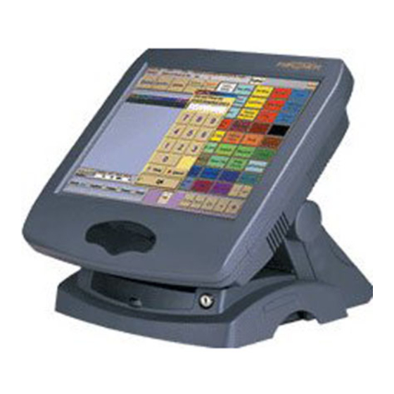
The PT-4000 provides you with a fast and accurate point-of-sales (POS) solution for use in supermarkets, information kiosks, restaurants, and other hospitality service areas. The 12.1 or 13.3-inch LCD panel displays provide a clear color TFT (DSTN optional) interface, giving superior resolution and monitor capabilities. -
Page 12: Configuration Options
The PT-4000 POS Station has many optional devices that you can connect Customer pole display PT-4000 POS Station Infrared keyboard Figure 1 – Sample Configuration Cash drawer Printer... -
Page 13: Package Contents
The PT-4000 POS Station comes securely packaged in a sturdy cardboard shipping carton. Upon receiving your PT-4000 POS Station, open the carton and carefully remove the contents. If anything is missing or damaged, please contact your dealer immediately. The shipping carton should contain the following items: One PT-4000 POS Station (including one pedestal with keylock) One power supply unit and AC power cord... -
Page 14: Options
Single, dual, or triple track magnetic card reader Barcode card reader Pole display for customer Rear display for customer PCM CIA or fax/modem Internal floppy drive or CD-ROM drive Internal Smart Card Reader RF (Radio Frequency) reader CCD (barcode scanner) Hard disk drive Infrared keyboard Supported operating systems:... -
Page 15: Front View
LCD panel CD-ROM or floppy disk drive (optional) Figure 2 – PT-4000 POS Station front view IR port Rear cover release lock CD-ROM/FDD cover release lock... -
Page 16: Rear View
Power switch Rear customer display (optional) Figure 3 – PT-4000 POS Station rear view Magnetic card reader (optional) I/O ports (behind panel) -
Page 17: The Ir Communication Module (Optional)
The PT-4000 POS Station is equipped with an Infrared (IR) communication module located on the front of the station. If you are having trouble finding this module, please see Front View on page 5. The IR module consists of one Light Emitting Diode (LED) and one photo sensor. -
Page 18: The Ir Keyboard (Optional)
The PT-4000 POS Station has an optional IR keyboard, providing greater expandability and flexibility for setting up and maintaining the station. The IR keyboard has integrated firmware, and is automatically installed in Windows 2000/ME/98/95/NT. Refer to the following illustration for proper usage of the IR keyboard: Figure 4 –... -
Page 19: Rotating The Lcd Panel
The LCD panel can be rotated to provide convenient access to the CD- ROM/FDD drive and t o enable you to change the HDD drive. The rotation provides flexible viewing angles for all types of environments: Figure 5 – Rotating the LCD panel... -
Page 20: Wall Mounting Option
The PT-4000 POS Station can be mounted on a wall providing greater versatility in setting up your POS system: Figure 6 – PT-4000 POS Station secured to a wall Contact your dealer for details about mounting options. This concludes Chapter 1. The next chapter covers installation of the system. -
Page 21: Chapter 2: Setting U P The System
Computer components and electronic circuit boards can be damaged by discharges of static electricity. Working on computers that are still connected to a power supply can be extremely dangerous. Follow the simple guidelines below to avoid damage to your computer or injury to yourself. -
Page 22: Before You Begin
Make sure you have a stable, clean working environment. Dust and dirt can get into computer components and cause a malfunction. Use containers to keep small components separated. Putting all small components in a safe container keeps them from becoming lost. Adequate lighting and proper tools can prevent you from accidentally damaging the internal components. -
Page 23: Pt-4000 Pos Station Overview
The PT-4000 POS Station is configured into three main units. This section describes these units. The LCD Panel/CPU unit provides all computer functions. This unit contains the following components: Mainboard On/off switch Serial and parallel port connections Micro PCI connection MSR connection HDD and power indicators Touchscreen... -
Page 24: Attaching Optional Devices
This section provides information on installing optional devices. Notes! 1. The arrows in the following procedures show the direction of movement to remove/replace a device or component, or to turn a screw or key to release a device. 2. All connectors are keyed to only attach one way. 3. -
Page 25: Removing The
Before proceeding Remove the Rear Cover (see page 14). Follow these instructions: At the rear of the unit, remove the two screws from the PCB board cover: Lift the PCB board cover:... - Page 26 Press the front cover clips down to release the front cover: Remove the front cover:...
-
Page 27: Attaching The Cd-Rom
To install a CD-ROM drive in your PT-4000 POS Station, refer to the following: Components Required Slim-type CD-ROM drive Control PCB CD-ROM plates (center, right, left) M2.0*3 screws x 7 M3*6 screws x 8 Before Proceeding Remove the Rear Cover (see page 14). Remove the Front Cover (see page 15). - Page 28 Secure the PCB to the CD-ROM drive with three M2.0*3 screws: Secure the right and left plates to the CD-ROM drive with four M2.0*3 screws: Secure the CD-ROM drive right and left plates to the center plate with four M3*6 screws:...
- Page 29 Connect the CD-ROM cable to the CD-ROM drive connector (A). Connect a power cable to the PCB board (B): Secure the CD-ROM drive to the system base with four M3*6 screws: Replace the Front Cover. Replace the Rear Cover.
-
Page 30: Attaching The Floppy Disk Drive
To install a Floppy Disk Drive (FDD) in your PT-4000 POS Station, refer to the following: Components Required Slim-type FDD FDD cable Control PCB and PCB cable FDD center and holding plates M2.0*3 screws x 4 M3*6 screws x 8 Before Proceeding Remove the Rear Cover (see page 14). - Page 31 Open the IDE access cover and remove the two screws from the IDE connector cover: Remove the IDE connector cover: Connect the FDD cable to the FDD connector: Note! Pin 1 on the cable is marked with a red stripe. Replace the IDE connector cover: Disconnect the video cable by pushing on the sides of the...
- Page 32 Pass the FDD cable through the opening as shown and reconnect the video cable: Secure the holding plate to the FDD with four M2.0*3 screws: 10. Unlock the IPC safety locks on the FDD and the PCB board by lifting up at the sides as shown here: 11.
- Page 33 12. Attach the FDD to the center plate with four M3*6 screws: 13. Connect the FDD cable and a power cable to the PCB board: 14. Secure the FDD to the system with four M3*6 screws: Replace the Front Cover. Replace the Rear Cover.
-
Page 34: Replacing The Hard Disk Drive
To upgrade the Hard Disk Drive (HDD) on your PT-4000 POS Station, refer to the following: Components Required Replacement HDD Before Proceeding Remove the Rear Cover (see page 14) Remove the Front Cover (see page 15) Remove the CD-ROM if installed (see page 17) Remove the FDD if installed (see page 20) Disconnect the power cable (A) and the IDE cable (B):... - Page 35 To remove the HDD and base plate, lift up at the rear of the base plate (A), then away from the system (B): Remove the four screws that secure the HDD to the base plate: Reverse the above procedure to install the new HDD. Replace the Front Cover.
-
Page 36: Attaching The Magnetic Strip Reader
To install a Magnetic Strip Reader (MSR) on your PT-4000 POS Station, refer to the following: Note! The MSR can be configured as a side-swipe or front-swipe unit. Components Required M3*10 screws x 2 MSR x 1 Front-swipe MSR Installation Remove the cover plate on the right side of the LCD panel as shown:... - Page 37 Attach the MSR unit to the LCD panel. Ensure that the cable is folded inside the opening: Secure the MSR unit to the LCD panel with two M3*10 screws:...
- Page 38 Side -swipe MSR Installation Remove the cover plate on the right side of the LCD panel as shown: Connect the MSR cable. Ensure that it is attached securely: Attach the MSR unit to the LCD panel. Ensure that the cable is folded inside the opening:...
- Page 39 Secure the MSR unit to the LCD panel with two M3*6 screws:...
-
Page 40: Attaching The Rear Customer Display
To install a Rear Customer Display to your PT-4000 POS Station, refer to the following: Components Required M3*8 screws x 2 Rear Customer Display Display backplate Cable Before Proceeding Remove the Rear Cover (see page 14) Turn the cover over and remove the two screws to separate the dummy cover from the rear cover: Ensure that the display unit is... - Page 41 Secure the display to the rear cover with two M3*8 screws: Connect the display cable (the cable is keyed to only connect one way): At the rear of the POS, remove the two screws from the PCB board cover: Lift the PCB board cover:...
- Page 42 Move the PCB board cover to the side and locate the PCB board. Short pins 5-6 (DC 12V) of the Power PCB jumper JP1. Replace the PCB board cover and secure it with the two screws: (See Appendix C for more information on jumper locations.) Connect the display cable to COM Replace the Rear Cover.
-
Page 43: Attaching The Customer Pole Display
You can connect the Customer Pole Dis play to COM 3 if you prefer to use it instead of the Rear Customer Display: Refer to the following: Components Required Customer Pole Display Before Proceeding Remove the Rear Cover (see page 14) Remove the two screws from the PCB board cover: Lift the PCB board cover:... - Page 44 Move the PCB board cover to the side and locate the PCB board. Short pins 5-6 (DC 12V) of the Power PCB jumper JP1 (see Appendix C for the jumper location). Replace the PCB board cover and secure it with the two screws: Connect the display cable of the Customer Pole Display to COM 3:...
-
Page 45: Connecting I/O Devices
The PT-4000 POS Station supports many peripheral devices to expand the functionality of the station: Cash Drawer Network 5V/12V (LAN) Compliant Device Figure 7 – Connecting peripheral devices Note! The PT-4000 POS Station does not have the USB ports located near the cash drawer port. -
Page 46: Connecting A Ps/2 Keyboard And Mouse
Connect a keyboard and mouse to the PS/2 keyboard and mouse ports. 5V/12V Figure 8 – Connecting a PS/2 mouse or keyboard The keyboard can be connected even if you have installed the optional IR keyboard. Note! If your keyboard has an AT type connector, you must use an adapter. Contact your dealer for details. -
Page 47: Connecting A Vga Monitor
You can connect an auxiliary VGA display to the VGA port. 5V/12V POWER IN 24V/OUT COM1 COM2 Figure 10 – Connecting an external monitor Refer to Windows online help for more information on using multiple monitors. Connect serial devices to the 9-pin D-type serial ports on the I/O port array. -
Page 48: Connecting A Cash Drawer
Connect the cash drawer RJ-11 connector to the RJ-11 port on the I/O port array. Cash Drawer 5V/12V Figure 12 – Connecting a cash drawer Connect USB devices to the USB ports on the I/O port array: Compliant Device Figure 13 – Connecting USB devices CASH POWER IN 24V/OUT... -
Page 49: Connecting Speakers
Connect stereo speakers to the speaker jack on the I/O port array: 5V/12V POWER IN COM1 Figure 14 – Connecting stereo s peakers Note! You must install the audio driver before you can listen to audio output with the speakers.Installing Audio on page 錯誤! 尚未定義書籤。. Connect a 10/100 Base-T Ethernet LAN to the RJ-45 jack on the I/O port array: Network... -
Page 50: Starting The System
Connect the power supply cables to the power jacks on the I/O port array: 5V/12V COM1 5V/12V POWER IN 24V/OUT CASH POWER IN 24V/OUT DRAWER COM2 +5/12V power supply for optional FDD, HDD, or CD-ROM drive AC adapter power cable plug +24V power supply for 24 volt devices COM3 MOUSE... -
Page 51: Turning The System On
Open the power switch cover and press the power switch to turn the system on: Open the cover and press the power switch Figure 16 – Turning the system on... -
Page 52: Adjusting The Display Brightness
As the system powers on, turn the dial located at the base of the LCD panel to adjust the display brightness for optimum viewing: Figure 17 – Adjusting display brightness Turn the dial to adjust the display brightness. -
Page 53: Chapter 3: Installing Drivers And Software
This section explains how to install the drivers for the PT4000 POS Station VGA, audio, LAN, Touchscreen, modem, and utilities. This section covers the installation of software for the PT-4000 POS Station. The PT-4000 POS Station comes with an autoinstall CD that will install the drivers for the station. - Page 54 Install VGA Drivers Sound Drivers LAN Drivers Other Drivers Utilities Click the buttons and follow the instructions on the screen to install drivers, read installation instructions, or open the manufacturer’s Web site. Note! If the screen doesn’t automatically appear, you have the Auto insert notification turned off in the Device Manager.
-
Page 55: Windows 2000
This section explains how to install the device drivers manually. Installing VGA Drivers Follow these instructions to install VGA device drivers for Windows 2000/ME/98/95/NT4.0: Windows 2000 Insert the driver CD into the CD-ROM drive. Click Start, Run. Type “D:\VGA\PANEL\WIN2000” in the Run Open dialog box, where D is your CD-ROM drive. - Page 56 10. When the Change Display dialog box appears, click OK. 11. When the Third-party Drivers dialog box appears, click Yes. Installing VGA Utilities Follow these instructions to install VGA device drivers for Windows 2000/ME/98/95/NT4.0 and Linux: Windows 2000 Insert the driver CD into the CD-ROM drive. Click Start, Run.
- Page 57 Linux Refer to the readme.txt and the SMI App Note - Linux installation guide for Lynxfamily.doc located in t h e directory D:\ VGA\SMI721\ LINUX\ (where D is your CD-ROM drive) for information on setting up the display utility in the Linux operating system. Installing Audio Follow these instructions to install audio device drivers for Windows 2000/ME/98/95NT4.0 and DOS:...
- Page 58 Installing LAN Follow these instructions to install LAN device drivers for Windows ME/2000/98/95/NT4.0: Note! For further instructions on installing the LAN drivers and associated software, check the Readme.txt file in the operating system subdirectory for information about installing the LAN driver for a particular OS. Windows ME/2000/98/95/NT Insert the driver CD into the CD-ROM drive.
-
Page 59: Other Drivers And Utilities
This section provides a description of the items Other Drivers and Utilities located on the CD-ROM. Other Drivers Drivers are provided for optional items to enhance your PT-4000 POS Station: Camera Driver Windows 2000/95 camera drivers are provided for use with video capture hardware such as a digital camera, enabling users to take customer photos for records and store them on the POS unit. -
Page 60: Opos Driver
Click Add. Check the box next to “Don’t detect my modem, I will select it from a list. Click Have Disk. Browse to the location of the modem driver on your CD-ROM. Click OK and follow the instructions on the screen to install the modem driver for Windows 2000. -
Page 61: Installing The Touchscreen
Installing the Touchscreen Follow these instructions to install the Elo TouchSystems Touchscreens device drivers for Windows ME/2000/98/95: Windows 2000 Insert the driver CD into the CD-ROM drive. Click Start, Run. Type “D:\DRIVERS\TOUCH\WIN2000\SETUP.EXE” in the Run Open dialog box, where D is your CD-ROM drive.. Press OK. - Page 62 Utilities The following utilities are provided to enhance your PT-4000 POS Station: Cashdraw CD7220 Speaker This concludes Chapter 3. The next chapter covers using the Touchscreen. Provides Windows 2000/95 utilities to initialize, trigger, and provide status information for the optional cash drawer.
-
Page 63: Chapter 4: Using The Touchscreen
Other menus, for example the Format or Tools menu in Microsoft Word, are opened in the same way. Use single-tapping to select an object or item on the desktop or from a menu. For most applications, single-tapping is equivalent to single- clicking the left mouse button. - Page 64 Enable the right mouse button function from the icon in the toolbar The virtual mouse appears on the desktop: Virtual mouse Click the virtual mouse’ s right button. The right button is enabled: Click an item on the desktop. The properties menu appears:...
- Page 65 Note! To access advanced features of the Elo Touchscreen, double-click the Elo Touchscreen icon in the taskbar to open the Elo Touchscreen Properties dialog box: When you right-click an object, the virtual mouse goes back to left-button mode.
- Page 66 The Elo Touchscreen Properties dialog box enables you to change the COM 4 port assigned to the Touchscreen, align the cursor, change button functions, assign sounds to events, and run diagnostics on the Touchscreen. This concludes Chapter 4. The next chapter covers the BIOS.
-
Page 67: Chapter 5: Using Bios
This chapter describes the BIOS Setup for the PT-4000 POS Stations. The computer uses the latest Award BIOS with support for Windows Plug and Play. The CMOS chip on the mainboard contains the ROM Setup instructions for configuring the mainboard BIOS. The BIOS (Basic Input and Output System) Setup Utility displays the system's configuration status and provides you with options to set system parameters. -
Page 68: The Standard Configuration
A standard configuration has already been set in the Setup Utility. However, we recommend that you read this chapter in case you need to make any changes in the future. This Setup Utility should be used: when changing the system configuration when a configuration error is detected and you are prompted to make changes to the Setup Utility when trying to resolve IRQ conflicts... -
Page 69: Entering The Setup Utility
When you power on the system, BIOS enters the Power-On Self Test (POST) routines. POST is a series of built-in diagnostics performed by the BIOS. After t he POST routines are completed, the following message appears: Press DEL to enter SETUP Pressing the delete key STANDARD CMOS SETUP BIOS FEATURES SETUP... -
Page 70: Using Bios
Shift + F2 Using BIOS When you start the Setup Utility, the main menu appears. The main menu of the Setup Utility displays a list of the options that are available. A highlight indicates which option is currently selected. Use the cursor arrow keys to move the highlight to other options. -
Page 71: The Pt-4000 Pos Station Bios
This section describes the BIOS for the PT-4000 POS Station. This option displays basic information about your system. Date (mm:dd:yy) : Wed, Mar 7 2001 Time (hh:mm:ss) : 1 : 19 : 12 HARD DISKS TYPE Primary Master : Auto Primary Slave : Auto Secondary Master: Auto... - Page 72 Hard Disks Your computer has two IDE channels (Primary and Secondary) and each channel can be installed with one or two devices (Master and Slave). Use these items to configure each device on the IDE channel. When configured, the following items are displayed: TYPE –...
- Page 73 Drive A/Drive B (1.44M, 3.5 in./None) These items define the characteristics of any diskette drive attached to the system. You can connect one or two diskette drives. Video (EGA/VGA) This item defines the video mode of the system. This mainboard has a built-in VGA graphics system;...
-
Page 74: Virus Warning
This option displays advanced information about your system. Virus Warning CPU Internal Cache External Cache CPU L2 Cache ECC Checking Processor Number Feature Quick Power On Self Test Boot From LAN First Boot Sequence Swap Floppy Drive Boot Up Floppy Seek Boot Up NumLock Status Gate A20 Option Typematic Rate Setting... - Page 75 CPU L2 Cache ECC Checking This item enables or disables ECC (Error Correction Code) error checking on the CPU cache memory. We recommend that you leave this item at the default setting. The default setting is Enabled. Processor Number Feature Some new processors are installed with a unique processor number.
- Page 76 Boot Up NumLock Status This item defines if the keyboard Num Lock key is active when your system is started. The default setting is On. Gate A20 Option This item defines how the system handles legacy software that was written for an earlier generation of processors. Leave this item at the default setting.
- Page 77 HDD S.M.A.R.T Capability The S.M.A.R.T. (Self-Monitoring, Analysis, and Reporting Technology) system is a diagnostics technology that monitors and predicts device performance. S.M.A.R.T. software resides on both the disk drive and the host computer. The default setting is Disabled. The disk drive software monitors the internal performance of the motors, media, heads, and electronics of the drive.
-
Page 78: Chipset Features Setup
These options define critical timing parameters of the mainboard. You should leave the items on this page at their default settings unless you are very familiar with the technical specifications of your system hardware. If you change the values incorrectly, you may introduce fatal errors or recurring instability into your system. - Page 79 SDRAM CAS Latency Time This item enables you to select the CAS latency time in HCLKs of 2/2 or 3/3. The value is set at the factory depending on the DRAM installed. Do not change the values in this field unless you change the specifications of the installed DRAM or the installed CPU.
-
Page 80: Power Management Setup Option
Memory Hole At 15M–16M This item is used to reserve memory space for ISA expansion cards that require it. The default setting is Disabled. Passive Release When enabled the CPU to PCI bus access is allowed during passive release. Otherwis e, only the PCI master access to local DRAM is permitted. -
Page 81: Video Off Method
If the system is suspended or has been powered down by software, it can be resumed by a wake up call that is generated by incoming traffic to a modem, a LAN card, a PCI card, or a fixed alarm on the system realtime clock. Power Management PM Control by APM Video Off Method... - Page 82 Video Off After This option defines if the video is powered down when the system is put into suspend mode. The default setting is N/A. Doze Mode The system speed will change from turbo to slow if no Power Management events occur for a specified length of time. Full power function will return when a Power Management event is detected.
-
Page 83: Reload Global Timer Events
** Reload Global Timer Events ** Global Timer (power management) events are I/O events whose occurrence can prevent the system from entering a power saving mode or can awaken the system from such a mode. In effect, the system remains alert for anything that occurs to a device that is configured as Enabled, even when the system is in a power-down mode. -
Page 84: Pnp Os Installed
These options configure how PnP (Plug and Play) and PCI expansion cards operate in your system. Both the ISA and PCI buses on the mainboard use system IRQs (Interrupt ReQuests) and DMAs (Direct Memory Access). You must set the IRQ and DMA assignments correctly through the PnP/PCI Configurations Setup utility;... - Page 85 If you cannot get a legacy ISA (Industry Standard Architecture) expansion card to work properly, you might be able to solve the problem by changing this item to Manual, which displays the IRQ Resources and Memory Resources list. In the IRQ Resources list, if you change any of the IRQ assignations to Legacy ISA, then that Interrupt Request Line is reserved for a legacy ISA expansion card.
-
Page 86: Ide Hdd Block Mode
This option displays a list of items that defines the operation of peripheral components on the s ystem's input/output ports. IDD HDD Block Mode IDE Primary Master PIO IDE Primary Slave PIO IDE Secondary Master PIO IDE Secondary Slave PIO IDE Primary Master UDMA IDE Primary Slave UDMA IDE Secondary Master UDMA... - Page 87 IDE Primary/Secondary Master/Slave UDMA Each IDE channel supports a master device and a slave device. This mainboard supports UltraDMA technology, which provides faster access to IDE devices. The default setting is Auto. If you install a device that supports UltraDMA, change the appropriate item on this list to Auto.
- Page 88 UART Mode Select This field is available if the Onboard Serial Port 2 field is set to any option but Disabled. UART Mode Select enables you to select the infrared communication protocol-Normal (default), IrDA, or ASKIR. IrDA is an infrared communication protocol with a maximum baud rate up to 115.2K bps.
- Page 89 SPP allows data output only. Extended Capabilities Port (ECP) and Enhanced Parallel Port (EPP) are bi-directional modes, allowing both data input and output. ECP and EPP modes are only supported with EPP and ECP aware peripherals. ECP Mode Use DMA When the onboard parallel port is set to ECP mode, the parallel port can use DMA 3 or DMA 1.
-
Page 90: Other Bios Options
This section covers the other options that are available from the main screen: STANDARD CMOS SETUP BIOS FEATURES SETUP CHIPSET FEATURES SETUP POWER MANAGEMENT SETUP PNP/PCI CONFIGURATION LOAD BIOS DEFAULTS LOAD SETUP DEFAULTS ESC : Quit F10 : Save&Exit If your system has an IDE hard drive, you can use this utility to d etect its parameters and enter them into the Standard CMOS Setup automatically. -
Page 91: Load Bios Defaults Option
This option opens a dialog box that lets you load fail-safe defaults for all appropriate items in the Setup Utility. Follow these instructions: From the main screen, scroll to Load BIOS Defaults. Press <Enter> to open the Load BIOS Defaults screen. Press <Y>. -
Page 92: Set Supervisor And User Passwords Options
These items can be used to install a password. A Supervisor password takes precedence over a User password, and the Supervisor can limit the activities of a User. To install a password, follow these steps: Highlight the item Set Supervisor/User Password on the main menu and press <Enter>. -
Page 93: Save & Exit Setup Option
& & Highlight this item and press <Enter> to save the changes that you have made in the Setup Utility and exit the Setup Utility. When the Save and Exit dialog box appears, press <Y> to save and exit, or press <N> to return to the main menu: Highlight this item and press <Enter>... -
Page 94: A A S
Intel Celeron 300~600 MHz+, P III 500~750 MHz+ 64 MB Memory, expandable to 512 MB DiskOnChip expandable to 288 MB, share with SSD (optional) 3.5-inch IDE hard drive or 2.5-inch IDE hard drive (optional) 12.1/13.3-inch LCD panel, color, TFT (Optional for DSTN) Touchscreen (resistive or capacitive) I/O Interfaces: –... - Page 95 Support DOS, Windows ME/2000/98/95/NT Safety & EMI: US, CUL, FCC, CE, VCCI Class A Dimensions: W x D x H: 12.8 x 13.4 x 12.4 (inch) (325 mm x 340 mm x 315 mm) (Packing Size: 18.3 x 23.2 x 16.3 (inch)) Net weight: 7.2 kg, Gross weight :12.8 kg...
-
Page 96: A B T
This appendix describes locating and solving problems that you may encounter while using your computer. Problems with your computer can be caused by something as minor as an unplugged power cord— or as major as a damaged hard disk. The information in this appendix is designed to help you find and solve minor problems. -
Page 97: Checking Cables And Connections
To check the power cables, and connections: Check the power outlet, the power cord, and any power switches that may affect your computer. Check the wall outlet or power strip with an item that you know is functioning properly (a lamp or radio is a convenient item for checking the power). -
Page 98: General Hardware Problems
If failure is detected in an area other than the mainboard (such as the keyboard or an adapter card), an error message is displayed on the screen and testing is stopped. If your system does not successfully complete the POST, but displays a blank screen, emits a series of beeps, or displays an error code, consult your dealer. -
Page 99: Contacting Your Dealer
Problem An unidentified message is displayed. The system cannot access the CD- ROM/DVD-ROM drive. You cannot operate the printer. You can’t save data to disk. You cannot use the mouse. If you still have a problem after reading the preceding sections, contact your dealer. -
Page 100: Appendix C: Jumper Settings
This appendix provides information on jumper settings on the PT-4000 POS Station. Location of PCB Boards The following illustration shows the location of the PCB boards. The rear cover is removed. Refer to page 14 for instructions on remo ving the rear cover: Figure 19 –... -
Page 101: Power Pcb Jumpers
Power PCB JP1: COM3 power jumper Value DC5V Setting Power PCB JP11, JP12: Cash drawer control jumper Setting JP11 JP12 JP12 JP11 Figure 20 – Power PCB Value PPD10 PPD11 DC12V Value -STB1 -AFD1... -
Page 102: Base Pcb Jumpers
Base VGA PCB JP1:COM1 power jumper Value Setting Base VGA PCB JP2:C OM2 power jumper Value Setting Note! These jumpers should only be accessed by your dealer. JP1, JP2 1-2 DC 5V 3-4 R1 5-6 DC12V Figure 21 – Base PCB DC5V DC5V DC12V... -
Page 103: Msr Pcb Jumpers
MSR PCB JP3:External keyboard decoder jumper Value EXT-KB Setting DECODE Note! These jumpers should only be accessed by your dealer. You can connect an RF (Radio Frequency) reader or CCD (barcode scanner) to JP4. Contact your dealer for details. Figure 22 – MSR PCB 3-5, 4-6 1-3, 2-4, 5-7, 6-8 BAT1...
Need help?
Do you have a question about the PT-4000i and is the answer not in the manual?
Questions and answers