Table of Contents
Advertisement
Quick Links
Advertisement
Table of Contents

Related Manuals for Partner PT-6910 Series


Summary of Contents for Partner PT-6910 Series
- Page 1 User Manual PT-6910 Series...
-
Page 3: Declaration Of Conformity
Copyright This publication, including all photographs, illustrations and software, is protected under international copyright laws, with all rights reserved. Neither this manual, nor any of the material contained herein, may be reproduced without written consent of the author. Disclaimer The information in this document is subject to change without notice. The manufacturer makes no representa- tions or warranties with respect to the contents hereof and specifically disclaims any implied warranties of merchantability or fitness for any particular purpose. -
Page 4: About This Manual
About this Manual PT-6910 Series POS Terminal Models This manual is for users of the PT-6910 Series. In the text we refer to any of these models as the PT-6910 Series, or to the specific model if there is a difference. -
Page 5: Table Of Contents
Adjusting the Customer Display Angle (PT-6910 / PT-6915F) .....10 Setup Considerations ...................10 Connecting Peripheral Devices ..............11 Connecting a Cash Drawer ................12 Powering the PT-6910 Series On and Off ............13 CHAPTER 2 BIOS SETUP ............15 About the Setup Utility .................15 Entering the Setup Utility ................16 BIOS Navigation Keys ................16... - Page 6 Installing a CompactFlash card (PT-6910 / PT-6915F) ........42 APPENDIX .................. 44 Troubleshooting ...................44 Tips for Troubleshooting ................44 The Power-On Self Test ................44 Beep Errors at POST ...................44 Beep Message Errors at POST ..............45 General Problems ..................46 Having the PT-6910 Series Serviced ............47 Specifications ....................48...
-
Page 7: Pt-6910 Series Pos Terminal Models
GETTING STARTED PT-6910 Series POS Terminal Models This manual is for users of the PT-6910 Series. In the text we refer to any of these models as the PT-6910 Series, or to the specific model if there is a difference. -
Page 8: Checking The Package Contents
Checking the package contents After you unpack the device check that the following items are included. Power Cable PT-6910 Series (Some units ship with customer display and MSR installed. Power Adapter System QIG Customer Display (optional) 1. User Manual and Driver CD 2. -
Page 9: Identifying Components
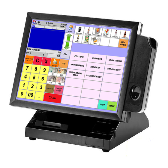
Identifying components This section describes the parts and connectors on the machine. Front-right view USB Cover Figure 1.2 Front-right view Component Description 15-inch TFT LCD touch screen Power Button USB Cover Green Power indicator LED Amber Hard drive activity LED... -
Page 10: Rear View
Rear view PT-6915 PT-6910 / PT-6915F Figure 1.3 Rear view Component Description Heat sink rear cover (PT-6915) CompactFlash card cover Rear cover Rear cover latches C H A P T E R 1 G E T T I N G S T A R T E D... - Page 11 I/O connectors 16 15 Figure 1.4 PT-6910 Series I/O connectors Connector Description Audio Line out Act LED (green) lights when network activity is detected RJ-45 (LAN) connector Link LED (orange) lights when the network is found PS/2 mouse connector COM3 connector...
- Page 12 Do not plug a phone line into the RJ-45 (ADSL or router) connector. Doing so can damage the connector. CAUTION COM6 is reserved for the optional customer display. NOTE NOTE C H A P T E R 1 G E T T I N G S T A R T E D...
-
Page 13: Removing The Rear Cover
Removing the rear cover Refer to the following to remove the rear cover. Tilt the display to its full vertical orienta- tion. Release the rear cover latches. Remove the rear cover. -
Page 14: Attaching The Customer Display (Pt-6910 / Pt-6915F)
Attaching the Customer Display (PT-6910 / PT-6915F) The PT-6910 and PT-6915F may ship with a customer display attached. If you ordered the display separately, refer to the following to attach it. 1. Remove the customer display cover by sliding it in the direction shown by the arrow. -
Page 15: Attaching The Customer Display (Pt-6915)
Attaching the Customer Display (PT-6915) The PT-6915 may ship with a customer display attached. If you ordered the display separately, refer to the following to attach it. 1. Connect the customer display cable. 2. Line up the bracket with the holes in the rear of the housing and secure with two screws. -
Page 16: Adjusting The Customer Display Angle (Pt-6910 / Pt-6915F)
Place the unit on a stable and even surface • Ensure there is enough room around the sides and rear of the PT-6910 Series for ventiliation • Ensure there is room to connect cables and that cables are long enough to reach peripheral... -
Page 17: Connecting Peripheral Devices
Connecting Peripheral Devices Peripheral devices such as a printer or scanner can be connected to the machine. Refer to the user manual of the device you are connecting for instructions on installing drivers where needed. MR HS AA SD RD TR ADSL modem Mouse Printer... -
Page 18: Connecting A Cash Drawer
IMPORTANT 1. Remove the rear cover (See “Removing the rear cover” on Page 7. 2. Connect the RJ-11 cable from the cash drawer to the RJ-11 connector on the PT-6910 Series as shown in Figure 1.8. Figure 1.8 Connecting a cash drawer Cashdrawer 3. -
Page 19: Powering The Pt-6910 Series On And Off
Powering the PT-6910 Series On and Off Refer to the following to power on and off the machine. Remove the rear cover . (See “Re- moving the rear cover” on page 7.) Connect the power cable to the power connector on the PT-6910... - Page 20 C H A P T E R 1 G E T T I N G S T A R T E D...
-
Page 21: Chapter 2 Bios Setup
CHAPTER 2 BIOS SETUP The primary function of the BIOS (Basic Input and Output System) is to identify and initiate component hardware. The BIOS parameters are stored in non-volatile BIOS memory (CMOS). CMOS contents don’t get erased when the computer is turned off. The following topics are described in this chapter. •... -
Page 22: Entering The Setup Utility
Entering the Setup Utility When you power on the system, BIOS enters the Power-On Self Test (POST) routines. POST is a series of built-in diagnostics performed by the BIOS. After the POST routines are completed, the following message appears: Press DEL to enter SETUP Press the delete key <Delete>... -
Page 23: Using Bios
Using BIOS When you start the Setup Utility, the main menu appears. The main menu of the Setup Utility displays a list of the options that are available. A highlight indicates which option is currently selected. Use the cursor arrow keys to move the highlight to other options. -
Page 24: Standard Cmos Features
Standard CMOS Features Selecting Standard CMOS Features on the main menu displays the following menu: Phoenix - AwardBIOS CMOS Setup Utility Standard CMOS Features Date (mm:dd:yy) Thu, Oct 22 2008 Item Help Time (hh:mm:ss) 8 : 33 : 14 IDE Channel 0 Master [ None] ►... - Page 25 IDE Channel 0/2/3 Master/Slave This field is used to configure the IDE hard drive installed in the system. Move the cursor to highlight the IDE Primary/Secondary Master/Slave fields and press <Enter>. The IDE Primary Master submenu opens: Phoenix - AwardBIOS CMOS Setup Utility IDE Channel 2 Master IDE HDD Auto-Detection [Press Enter]...
-
Page 26: Advanced Bios Features
Advanced BIOS Features Selecting Advanced BIOS Features on the main menu opens up this screen: Phoenix - AwardBIOS CMOS Setup Utility Advanced BIOS Features CPU Feature [Press Enter] Item Help ► Hard Disk Boot Priority [Press Enter] ► First Boot Device [USB-ZIP] Second Boot Device [USB-CDROM]... -
Page 27: Cpu Feature
CPU Feature Selecting CPU Feature opens up this screen. Phoenix - AwardBIOS CMOS Setup Utility CPU Feature Delay Prior to Thermal [16 Min] Item Help Thermal Management Thermal Monitor 1 Execute Disable Bit [Enabled] Figure 2.5 CPU Feature submenu ↑↓→←:Move Enter:Select +/-/PU/PD:Value F10:Save ESC:Exit F1:General Help F5:Previous Values F6:Fail-Safe Defaults F7:Optimized Defaults... -
Page 28: Hard Disk Boot Priority
Hard Disk Boot Priority Selecting Hard Disk Boot Priority opens up this screen. Phoenix - AwardBIOS CMOS Setup Utility Hard Disk Boot Priority Ch2 M. : ST380815AS Item Help 2. Bootable Add-in Cards Figure 2.6 Hard Disk Boot Priority menu ↑↓→←:Move Enter:Select +/-/PU/PD:Value F10:Save ESC:Exit F1:General Help F5:Previous Values F6:Fail-Safe Defaults... -
Page 29: Advanced Chipset Features
Advanced Chipset Features This option displays critical timing parameters of the mainboard. Leave the items on this menu at their default settings unless you are very familiar with the technical specifications of the system hardware. If you change the values incorrectly, you may introduce fatal errors or recurring instability into the system. Phoenix - AwardBIOS CMOS Setup Utility Advanced Chipset Features DRAM Timing Selectable... - Page 30 System/Video BIOS Cacheable These items allow the video and/or system to be cached in memory for faster execution. We recommend that you leave these items at the default value. The default setting is Enabled/Disabled. ** VGA Setting ** The following items allow you to configure the settings for On-Chip VGA. On-Chip Frame Buffer Size This item is used to select the video frame buffer size.
-
Page 31: Integrated Peripherals
Integrated Peripherals This option defines the operation of peripheral components on the system’s input/output ports. Phoenix - AwardBIOS CMOS Setup Utility Integrated Peripherals OnChip IDE Device [Press Enter] Item Help ► Onboard Device [Press Enter] ► SuperIO Device [Press Enter] ►... -
Page 32: Onchip Ide Device
► OnChip IDE Device Use this item to enable or disable the PCI IDE channels that are integrated on the mainboard. Select the item and press <Enter> to open the following menu: Phoenix - AwardBIOS CMOS Setup Utility OnChip IDE Device IDE HDD Block Mode [Enabled] Item Help... - Page 33 On-Chip Secondary Use this item to enable or disable the PCI IDE channels that are integrated on the mainboard. The default setting is Enabled. IDE Secondary Master/Slave PIO Each IDE channel supports a master device and a slave device. These four items let you assign which kind of PIO (Programmed Input/Output) is used by IDE devices.
-
Page 34: Onboard Device
► Onboard Device Use this item to enable or disable the PCI devices that are integrated on the mainboard. Select the item and press <Enter> to open the following menu: Phoenix - AwardBIOS CMOS Setup Utility Onboard Device USB Controller [Enabled] Item Help USB 2.0 Controller... -
Page 35: Superio Device
► SuperIO Device Use this item to change settings for I/O devices. Select the item and press <Enter> to open the following menu: Phoenix - AwardBIOS CMOS Setup Utility SuperIO Device Onboard Serial Port 1 [3F8/IRQ4] Item Help Onboard Serial Port 2 [2F8/IRQ3] Onboard Parallel Port [378/IRQ7]... -
Page 36: Power Management Setup
Power Management Setup Use these items to control system power management. Modern operating systems take care of much of the power management. This mainboard supports ACPI (Advanced Configuration and Power Interface). Phoenix - AwardBIOS CMOS Setup Utility Power Management Setup ACPI Function [Enabled] Item Help... -
Page 37: Suspend Mode
Suspend Mode The CPU clock will be stopped and the video signal will be suspended if no Power Management events occur for a specified length of time. Full power will return when a Power Management event is detected. Options are from 1 Min to 1 Hour and Disabled. The default setting is Disabled. HDD Power Down The IDE hard drive will spin down if it is not accessed within a specified length of time. -
Page 38: Pnp/Pci Configurations
PnP/PCI Configurations This option configures how PnP (Plug and Play) and PCI expansion cards operate in the system. Both the ISA and PCI buses on the mainboard use system IRQs (Interrupt ReQuests) and DMAs (Direct Memory Access). You must set up the IRQ and DMA assignments correctly through the PnP/PCI Configurations menu; otherwise, the mainboard will not work properly. -
Page 39: Irq Resources
► IRQ Resources This menu can only be accessed when the Resources Controlled by menu is set to Manual. In the IRQ Resources sub-menu, if you change any of the IRQ assignations to Legacy ISA, then that Interrupt Request Line is reserved for a legacy ISA expansion card. Press <Esc> to close the IRQ Resources sub-menu. Phoenix - AwardBIOS CMOS Setup Utility IRQ Resources IRQ-3 assigned to... -
Page 40: Pc Health Status
PC Health Status On mainboards that support hardware monitoring, this item lets you monitor the parameters for critical voltages, and critical temperatures. Several fields are for information only and are not configurable. Phoenix - AwardBIOS CMOS Setup Utility PC Health Status CPU Warning Temperature [Disabled] Item Help... -
Page 41: Frequency/Voltage Control
Frequency/Voltage Control Use these items to control system frequency and voltage. Phoenix - AwardBIOS CMOS Setup Utility Frequency/Voltage Control Spread Spectrum [Enabled] Item Help Figure 2.16 Frequency/ Voltage Control menu ↑↓→←:Move Enter:Select +/-/PU/PD:Value F10:Save ESC:Exit F1:General Help F5:Previous Values F6:Fail-Safe Defaults F7:Optimized Defaults Spread Spectrum When the motherboard clock generator pulses, the extreme values (spikes) of the pulses creates EMI... -
Page 42: Other Bios Options
Other BIOS Options This section covers the other options that are available from the main menu: Phoenix - AwardBIOS CMOS Setup Utility Standard CMOS Feature Frequency/Voltage Control ► ► Advanced BIOS Features Load Fail-Safe Defaults ► Advanced Chipset features Load Optimized Defaults ►... -
Page 43: Exit Without Saving
Set Supervisor and User Passwords These items can be used to install a password. A Supervisor password takes precedence over a User password, and the Supervisor can limit the activities of a User. To install a password, follow these steps: 1. - Page 44 C H A P T E R 2 B I O S S E T U P...
-
Page 45: Chapter 3 Upgrading Components
CHAPTER 3 UPGRADING COMPONENTS This chapter describes how to upgrade components for the PT-6910 Series. The following topics are described. • Safety and precautions on page 3 • Before you begin on page 3 • Upgrading the hard drive on page 3 Safety and Precautions Computer components and electronic circuit boards can be damaged by discharges of static electricity. -
Page 46: Before You Begin
Before You Begin Make sure you have a stable, clean working environment. Dust and dirt can get into components and may cause mal-function. Adequate lighting and proper tools can prevent you from accidentally damaging the internal components. Most of the electrical and mechanical connections can be disconnected by using your fingers. It is recommended that you do not use needle-nosed pliers to disconnect connectors as these can damage the soft metal or plastic parts of the connectors. - Page 47 4. Remove the two screws which secure the plate to the chassis, then remove the screws from the sides of the hard disk. Disconnect the SATA/power connector. 5. Secure the new hard disk onto the HDD tray, and then secure the tray to the chassis.
-
Page 48: Installing A Compactflash Card (Pt-6910 / Pt-6915F)
The CompactFlash card reader uses an IDE (Integrated Drive Electronics) interface and only supports storage cards. Plug and play is not supported so you must insert the card before you turn the PT-6910 Series POS on. After inserting a CompactFlash card, replace the cover to prevent the card from being accidently removed while power is on. -
Page 50: Appendix
If a failure is detected in an area other than the mainboard (such as the keyboard or an adapter card), an error message is displayed on the screen and testing is stopped. If your system does not successfully complete the POST, but displays a blank screen, have the PT-6910 Series serviced. -
Page 51: Beep Message Errors At Post
The battery may be weak. Replace the battery. CMOS CHECKSUM ERROR The CMOS may be corrupt. Have the PT-6910 Series serviced. HARD DISK(S) FAIL (80) HDD reset failed. Have the PT-6910 Series serviced. HDD controller diagnostics HARD DISK(S) FAIL (40) Have the PT-6910 Series serviced. -
Page 52: General Problems
Check the boot sequence in the BIOS setup utility. press any key” You hear irregular beeps during operation of the Have the PT-6910 Series serviced. computer and the system halts. An unidentified message is displayed. Reboot the computer and run the BIOS Setup Utility. -
Page 53: Having The Pt-6910 Series Serviced
If you are unable to solve the problem, you should have the terminal serviced. Pack the terminal in the original carton. (See “Unpacking the PT-6910 Series” on page 1.) Include a description of the problem and a checklist of the steps you took when trying to fix the problem. The information may be useful to the service... -
Page 54: Specifications
Specifications 15” TFT color LCD, resolution is 1024 x 768 Touch 5-wire Resistive touch (RS-232 interface) PT-6910 Intel Celeron-M Processor @ 1GMhz, L2 Cache 0KB, FSB 400MHz, w/o fan PT-6915 Intel Celeron-M Processor @ 1.5GMhz, L2 Cache 1M, FSB 400MHz, w/o fan PT-6915F Intel Celeron-M Process @ 1.5GHz, L2 Cache, 1M, FSB, 400MHz, w/fan... - Page 55 Operating Windows XP, XP embedded, CE.Net, Linux (Fedora, SuSE), WEPOS System Power Supply AC 100V~240V/DC19V, 4.75A, 90 watt power adaptor (3P) Dimensions Physical: 344(W)x331(H)x259(D)mm Operating 0~+40˚C Temperature Storage -20˚C~+60˚C Temperature Operating & Storage 10%~80% Humidity Color Dark Charcoal Certification CE/FCC, Class A, UL, cUL, CB, VCCI, BSMI, 3C * Specification subject to change without prior notice...
- Page 56 A P P E N D I X...
Need help?
Do you have a question about the PT-6910 Series and is the answer not in the manual?
Questions and answers