Table of Contents
Advertisement
Quick Links
Advertisement
Table of Contents

Related Manuals for Partner PT-1630


Summary of Contents for Partner PT-1630
- Page 1 POS Terminal PT-1630 Sevice Manual...
-
Page 3: About This Manual
All product names used in this manual are the properties of their respective owners and are acknowledged. About this manual The service manual provides service information for the PT-1630. This manual is designed to help train service personnel to locate and fix failing parts on the machine. -
Page 4: Legislation And Weee Symbol
FCC Statement This device has been tested and found to comply with the limits for a Class A digital device, pursuant to part 15 of the FCC Rules, these limits are designed to provide reasonable protection against harmful interference when the device is operated in a commercial environment. This device generates, uses and can radiate fre- quency energy and, if not installed and used in accordance with this manual, may cause harmful interference to radio communications. -
Page 5: Table Of Contents
TABLE OF CONTENTS CHAPTER 1 INTRODUCING ............1 Identifying components .................1 Connector pin define ..................3 CHAPTER 2 BIOS SETUP ............7 About the Setup Utility ...................7 Entering the Setup Utility ................8 BIOS navigation keys ................8 Using BIOS ....................9 Main Screen ....................10 Advanced Menu ...................11 PCI Subsystem Settings ................12 PCI Express Settings ................13... - Page 6 CHAPTER 4 LOCATING THE PROBLEM ........35 General checkout guidelines ................35 Cash drawer checkout .................35 Power symptoms..................36 Network symptoms ..................37 USB symptoms ....................37 Peripheral-device symptoms ................37 Boot symptoms ....................37 Mainboard jumper ..................38 Mainboard connectors..................40 CHAPTER 5 REPLACING FIELD REPLACEABLE UNITS (FRUs) .....................
- Page 7 Figure 2.12 Chipset Menu ..............21 Figure 2.13 Boot Menu................24 Figure 2.14 Security Menu ..............25 Figure 2.15 Exit Menu ................26 Figure 4.1 Connecting a cash drawer ........... 36 Figure 4.2 PT-1630 mainboard jumper ..........38 Figure 4.3 PT-1630 mainboard connectors ........... 40...
-
Page 9: Chapter 1 Introducing
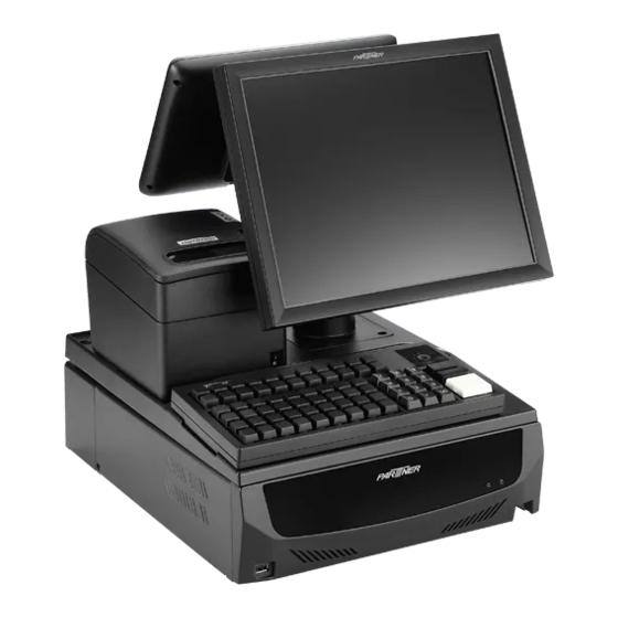
CHAPTER 1 INTRODUCING This chapter starts with identifying components. The following topics are described. • Identifying components on page 1 Identifying components This section describes the parts and connectors on the machine. Front view Figure 1.1 Front view Component Description USB port LED Power Indicator LED HDD Indicator... -
Page 10: Figure 1.2 Rear View
Rear view Figure 1.2 Rear view Connector Description Connector Description Fan hole USB 2.0 ports Power connector RJ-45 LAN port COM4 port USB 3.0 ports COM3 port COM1 port COM5 port COM2 port USB24V (optional) Primary VGA port USB12V (optional) Secondary VGA port USB12V (optional) MIC-In... -
Page 11: Connector Pin Define
Connector pin define This section describes the connectors pin define. COM connector pin define Signal Signal SOUT VGA connector pin define Signal Signal Signal AGND Green AGND DDC DAT Blue AGND Horizontal Sync Vertical Sync DDC CLK USB 2.0 connector pin define Signal USB Vcc USB -... - Page 12 USB 3.0 connector pin define Signal Signal USB Vcc StdA_SSTX- USB - GND_DRAIN USB + StdA_SSRX+ USB GND StdA_SSRX- StdA_SSTX+ LAN connector pin define Signal Signal TXA+ TXC- TXA- TXB- TXB+ TXD+ TXC+ TXD- RJ-11 Cash Drawer connector pin define Signal CASEOPEN2 CASH1...
- Page 13 PS/2 connector pin define Signal Keyboard Data Keyboard Clock DC 12V output connector pin define Signal +12V SATA connector pin define Signal Signal SATA_RX- SATA_TX+ SATA_RX+ SATA_TX-...
- Page 14 USB 12V connector pin define Signal Signal +12V USB + +12V USB - USB Vcc USB 24V connector pin define Signal Signal +24V USB + +24V USB - USB Vcc C H A P T E R 1 I N T R O D U C I N G...
-
Page 15: Chapter 2 Bios Setup
CHAPTER 2 BIOS SETUP The primary function of the BIOS (Basic Input and Output System) is to identify and initiate component hardware. The BIOS parameters are stored in non-volatile BIOS memory (CMOS). CMOS contents don’t get erased when the computer is turned off. The following topics are described in this chapter. •... -
Page 16: Entering The Setup Utility
Entering the Setup Utility When you power on the system, BIOS enters the Power-On Self Test (POST) routines. POST is a series of built-in diagnostics performed by the BIOS. After the POST routines are completed, the following message appears: Press DEL to run Setup Press the delete key <Delete>... -
Page 17: Using Bios
Using BIOS When you start the Setup Utility, the main screen appears. The main screen of the Setup Utility displays a list of the options that are available. A highlight indicates which option is currently selected. Use the cursor arrow keys to move the highlight to other options. -
Page 18: Main Screen
Main Screen Once you enter AMI UEFI BIOS Setup Utility, the Main Menu will appear on the screen providing an overview of the basic system information. Figure 2.2 Main Screen System Overview This screen displays System BIOS Information, Processor, System memory, System Time and System Date. BIOS Information Shows system information including UEFI BIOS version, model name, marketing name, built date, etc. -
Page 19: Advanced Menu
Advanced Menu The Advanced Menu allows you to configure the settings of CPU, Super I/O, Power Management, and other system devices. Figure 2.3 Advanced Menu Launch PXE OpROM This item enables or disables boot Options for legacy network devices with option ROM. Options: Disabled (Default) / Enabled Launch Storage OpROM This item enables or disables boot Options for legacy mass storage devices with option ROM. -
Page 20: Pci Subsystem Settings
PCI Subsystem Settings Figure 2.4 PCI Subsystem Settings PCI ROM Priority In case of multiple option ROMs (Legacy and EFI Compatible), this item specifies what PCI Option ROM to launch Options: Legacy ROM (Default) / EFI Compatible ROM Above 4G Decoding Enables or disables 64bit capable device to be decoded in above 4G address space (only if system support 64 bit PCI decoding). -
Page 21: Pci Express Settings
PCI Express Settings Figure 2.5 PCI Express Settings Relaxed Ordering Enables or disables PCI express device No snoop option. Options: Disabled (Default) / Enabled Extended Tag If enabled allows device to use 8-bit tab field as a requester. Options: Disabled (Default) / Enabled No Snoop This item enables or disables PCI Express Device No Snoop option. -
Page 22: Acpi Settings
ACPI Settings Figure 2.6 ACPI Settings Enable ACPI Auto Configuration This item enables or disables BIOS ACPI auto configuration. Options: Disabled (Default) / Enabled Enable Hibernation This item enables or disables system ability to hibernate (OS/S4 sleep state)/ This option may be not effective with some OS. -
Page 23: Cpu Configuration
CPU Configuration Figure 2.7 CPU Configuration Hyper-threading This item enables or disables for Windows XP and Linux (OS optimized for Hyper-Threading Technology) and Disabled for other OS (OS not optimized for Hyper-Threading Technology). When setting this item “Disabled” only one thread per enabled core is enabled. Options: Enabled (Default) / Disabled Active Processor Cores This item sets number of cores to enable in each processor package. -
Page 24: Sata Configuration
TCC Activation offset Offset from the factory TCC activation temperature Options: 0 (Default) CPU Max Current limit value (Amp) The maximum instantaneous current allow for primary plane. Options: 120 (Default) IGFX Max Current limit value (Amp) The maximum instantaneous current allow for secondary plane. Options: 35 (Default) SATA Configuration Figure 2.8 SATA Configuration... -
Page 25: Usb Configuration
USB Configuration Figure 2.9 USB Configuration Legacy USB Support This item determines if the BIOS should provide legacy support for USB devices like the keyboard, mouse, and USB drive. This is a useful feature when using such USB devices with operating systems that do not natively support USB (e.g. -
Page 26: Super Io Configuration
Super IO Configuration Figure 2.10 Super IO Configuration Serial Port1 Voltage select This item selects COM1 port pin 9 function. Options: No extrn Voltage (Default) / +5V / +12V Serial Port2 Voltage select This item selects COM2 port pin 9 function. Options: No extrn Voltage (Default) / +5V / +12V Watch Dog Degree This item allows you to determine the functional degree of Watch Dog. -
Page 27: H/W Monitor
H/W Monitor Figure 2.11 H/W Monitor Shutdown Temperature This item allows you to set up the CPU shutdown Temperature. Options: Disabled (Default) / 60°C/140°F / 65°C/149°F / 70°C/158°F / 75°C/167°F / 80°C/176°F / 85°C/185°F / 90°C/194°F Smart Fan Function This item enables or disables Smart Fan. Options: Enabled (Default) / Disabled Note: The following items appear only when you set the Smart Fan Function to [Enabled]... -
Page 28: Smart Fan Mode Configuration
Smart Fan Mode Configuration CPU/System Fan Smart Fan Control This item selects Smart Fan Mode. Temperature 1~4 Auto fan speed control. Fan speed will follow different temperature by different duty cycle 1-100 Duty Cycle 1~4 Auto fan speed control. Fan speed will follow different temperature by different duty cycle 1-100 Temperature 1~4 Auto fan speed control. -
Page 29: Chipset Menu
Chipset Menu This section describes configuring the PCI bus system. PCI, or Personal Computer Interconnect, is a system which allows I/O devices to operate at speeds nearing the speed of the CPU itself uses when communicating with its own special components. Figure 2.12 Chipset Menu PCH-IO Configuration Onboard Lan... -
Page 30: Pci Express Configuration
PCI Express Configuration Mini PCIE Slot This item controls the Mini PCI Express Root Port. Options: Enabled (Default) / Disabled ASPM This item sets PCI Express Active State Power Management settings. Options: Auto(Default) / Disabled / L0s / L1 / L0sL1 PCIe Speed This item selects PCI Express port speed. -
Page 31: System Agent (Sa) Configuration
System Agent (SA) Configuration Graphics Configuration Primary Display This item selects which of IGFX/PEG/PCI Graphics device should be Primary Display or select SG for Switchable Gfx. Options: Auto (Default) / IGFX / PEG / PCI Internal Graphics This item keeps IGD enabled based on the setup options. Options: Auto (Default) / Disabled / Enabled GTT Size This item selects GTT Size. -
Page 32: Boot Menu
Boot Menu Figure 2.13 Boot Menu Setup Prompt Timeout This item sets number of seconds to wait for setup activation key. Options: 2 (Default) Bootup NumLock State This item selects the keyboard NumLock state. Options: On (Default) / Off Full Logo Screen Display This item allows you to enable/disable Full Screen LOGO Show function. -
Page 33: Security Menu
Security Menu Figure 2.14 Security Menu Administrator Password This item sets Administrator Password. User Password This item sets User Password. -
Page 34: Exit Menu
Exit Menu This menu allows you to load the optimal default settings, and save or discard the changes tothe BIOS items. Figure 2.15 Exit Menu Discard Changes and Exit Abandon all changes made during the current session and exit setup. Save Changes and Reset Reset the system after saving the changes. -
Page 35: Chapter 3 Installing Drivers And Software
Use an external CD-ROM drive to install the drivers or copy the drivers to a USB flash drive and then plug to the machine. When you insert the CD ROM the following screen appears. Check PT-1630 that is listed under the “Install Terminal Drivers” and “Install Device Drivers” menus. -
Page 36: Intel Chipset Driver
Intel Chipset Driver The Intel Chipset Device Software updates the Windows XP/7 INF files so that the Intel chipset is correctly configured. Follow these instructions to install the chipset software : 1. Browse to the \DRIVER\chipset\Intel\Inf folder. 2. Double-click setup.exe. The following screen appears. Click Next to continue. 3. - Page 37 4. Browse the ReadMe Information, then click Next. 5. The Intel Chipset Software Utility files are installed to the system. When prompted to restart, select Yes, I want to restart my computer now. Then click Finish to restart the system.
-
Page 38: Intel Chipset Graphics Driver
Intel Chipset Graphics Driver This utility installs the Intel Extreme Graphics 2 drivers for Windows XP/2000. To install the drivers. 1. Browse to the \DRIVER\VGA\intel\ folder. 2. Double-click the executable file. The following screen appears. Click Next to continue. 3. Read the license agreement, then click Yes. C H A P T E R 3 I N S T A L L I N G D R I V E R S A N D S O F T W A R E... - Page 39 4. Browse the ReadMe Information, then click Next. 5. When installation is completed, select Yes, I want to restart my computer now. Then click Finish to restart the system.
-
Page 40: Lan Driver
LAN Driver The network driver support Windows XP/2000. Refer to the following to install the drivers. 1. Browse to the \DRIVER\LAN\RealTek folder. 2. Double-click the executable file. The following screen appears. Click Next to continue. 3. Click Install to begin installation. C H A P T E R 3 I N S T A L L I N G D R I V E R S A N D S O F T W A R E... - Page 41 4. When installation is completed, click Finish.
- Page 42 C H A P T E R 3 I N S T A L L I N G D R I V E R S A N D S O F T W A R E...
-
Page 43: Chapter 4 Locating The Problem
CHAPTER 4 LOCATING THE PROBLEM Refer to this section to locate the problem with the machine. The following topics are described. • General checkout guidelines on the page 35 • Cash drawer checkout on the page 35 • Power symptoms on the page 36 •... -
Page 44: Power Symptoms
Figure 4.1 Connecting a cash drawer Cashdrawer 2. Turn on the machine . Refer to the following to prevent incorrect cash drawer status detection by the system: Port I/O Port Address Condition Note Cashdrawer A High(1) → Close If Bit is set to Low to open the 50CH Control port cash drawer, after it must be set... -
Page 45: Network Symptoms
Network symptoms Symptom Corrective Procedure • Cannot access LAN 1. Confirm that network hub/switch (if present) is functioning correctly. 2. Reseat the RJ-45 cable. 3. Confirm green and orange LED activity of the RJ-45 jack. 4. Check the network TCP/IP settings. 5. -
Page 46: Mainboard Jumper
Mainboard jumper JCMOS1 JAT-ATX JPC1 JPC2 Figure 4.2 PT-1630 mainboard jumper Jumper Setting Description 1-2 Closed Normal Operation JCMOS1 (Default) (Clear CMOS Jumper) 2-3 Closed Clear CMOS data 1-2 Closed ATX Power (Default) JAT-ATX (AT-ATX Power Select Jumper) 2-3 Closed... - Page 47 Jumper Setting Description 1-2 Closed JPC1 3-4 Closed RING (Default) (COM5 Power Select Jumper) 5-6 Closed 1-2 Closed JPC2 3-4 Closed RING (Default) (COM6 Power Select Jumper) 5-6 Closed...
-
Page 48: Mainboard Connectors
COM3 connector to COM5 connector to COM4 Figure 4.3 PT-1630 mainboard connectors C H A P T E R 4 L O C A T I N G T H E P R O B L E M... -
Page 49: Chapter 5 Replacing Field Replaceable Units (Frus)
After replacing optional devices, make sure all screws, springs, or other small parts are in place and are not left loose inside the case. Metallic parts or metal flakes can cause electrical shorts. Only qualified personnel should perform repairs on the PT-1630. Damage due to unauthorized servicing is not covered by the warranty. -
Page 50: Before You Begin
CAUTION Before you begin Make sure you have a stable, clean working environment. Dust and dirt can get into the PT-1630 components and may cause malfunction. Adequate lighting and proper tools can prevent you from accidentally damaging the internal components. Most of the electrical and mechanical connections can be disconnected by using your fingers. -
Page 51: Chassis Cover
Chassis Cover 1. Remove the three screws securing the chassis cover to the chassis. 2. Slide the cover towards the rear and lift up to remove the cover. -
Page 52: Hard Disk Drive
Hard Disk Drive Before proceeding, remove the following FRUs. • “Chassis Cover” on page 43. 1. Remove the screws from the HDD compartment. 2. Pull the HDD out. 3. Remove four screws from the bottom of the HDD tray. 4. Remove the HDD. C H A P T E R 5 R E P L A C I N G F I E L D R E P L A C E A B L E U N I T S ( F R U s ) -
Page 53: Memory
Memory Before proceeding, remove the following FRUs. • “Chassis Cover” on page 43. 1. Open the clips. 2. Pull out the memory module. Battery Before proceeding, remove the following FRUs. • “Chassis Cover” on page 43. 1. Open the hock. 2. -
Page 54: Pci Pcb With Bracket
PCI PCB with Bracket Before proceeding, remove the following FRUs. • “Chassis Cover” on page 43. 1. Remove all cables from the PCI PCB. 2. Remove two screws. 3. Pull up the PCI PCB with bracket. Mainboard Before proceeding, remove the following FRUs. -
Page 55: Power Supply Unit
Power Supply Unit Before proceeding, remove the following FRUs. • “Chassis Cover” on page 43. 1. Remove all cables from the PSU. 2. Remove two screws from the PSU bracket. 3. Remove the PSU bracket. 4. Remove three screws from the PSU. -
Page 56: Cpu
Before proceeding, remove the following FRUs. • “Chassis Cover” on page 43. 1. Remove fan cable from the cooler. 2. Remove four screws. 3. Remove the cooler. 4. Press and hold the lever, and move it away from the lock, then lift the lever. -
Page 57: Installing A Pci Card
Installing a PCI Card To install a PCI card to your PT-1630 POS Terminal mainboard, refer to the following. Before installing an add-on card, check the documentation for the card carefully. If the card is not Plug_and_play, you may have to manually configure the card before installation. - Page 58 2. Remove the blanking plate or optional COM ports blacket from the chassis. 3. Slide the PCI card into place as shown: Line up the PCI card bracket with the bracket slot. Insert the edge connector of the PCI card into the expansion slot. Replace the add on card bracket screw 4.
-
Page 59: Installing The Cable Management Box
Installing the cable management box To add on the cable management box on your PT-1630 POS terminal refer to the following Components Required • Cable management box 1. Place the cable management box on the rear of the chassis. 2. Use two screws to fix the... -
Page 60: Install The Tray
Install the tray To install the tray on your PT-1630 POS terminal refer to the following Components Required • Cable management box • Tray 1. Place the tray on the chassis and cable management box and fastened. 2. Use eight screws to fix the tray. -
Page 61: Installing The Lcd Monitor Stand
Installing the LCD monitor stand To install the LCD monitor on your PT-1630 POS terminal refer to the following Before Proceeding • Install the cable management box • Install the tray 1. Place the LCD monitor stand into the groove of the tray. - Page 62 C H A P T E R 5 R E P L A C I N G F I E L D R E P L A C E A B L E U N I T S ( F R U s )
-
Page 63: Appendix Specification
APPENDIX SPECIFICATION Item PT-1630 Intel IVY or Sandy LGA1155 CPU Ivy Bridge i5-3550S 3.0 GHz Quad core, Celeron G540 2.5Ghz dual core, Ivy Bridge i7-3770 3.40 Ghz Quad core Ivy Bridge i3-3220 3.3 GHz dual core, Memory 2GB Standard, Maximum 16 GB (2 x DDR3 SO-DIMM Slots) Storage Internal 2.5”...
Need help?
Do you have a question about the PT-1630 and is the answer not in the manual?
Questions and answers