Table of Contents
Advertisement
Quick Links
Advertisement
Table of Contents

Related Manuals for Partner PT-6900


Summary of Contents for Partner PT-6900
- Page 1 PT-6900 User manual...
-
Page 3: Declaration Of Conformity
Copyright This publication, including all photographs, illustrations and software, is protected under international copyright laws, with all rights reserved. Neither this manual, nor any of the material contained herein, may be reproduced without writ- ten consent of the author. Disclaimer The information in this document is subject to change without notice. -
Page 4: Getting Started
Chapter 2 Upgrading Components: Chapter 3 BIOS Setup Utility: Appendix: Safety information Before installing and using the PT-6900 POS, take note of the following precautions: • Read all instructions carefully. • Do not place the unit on an unstable surface, cart, or stand. -
Page 5: Revision History
Revision history Version 1.0, April 2007... -
Page 7: Table Of Contents
Adjusting display angles ... 9 Setup considerations ... 9 Connecting peripheral devices ... 10 Connecting a cash drawer ... 11 Powering the PT-6900 on and off ... 12 Chapter 2 Upgrading Components ...13 Safety and precautions ... 13 Before you begin ... 14 Installing a hard disk drive (HDD) ... - Page 8 Troubleshooting ... 38 Tips for Troubleshooting ... 38 The Power-On Self Test ... 38 Beep Errors at POST ... 38 Beep Message Errors at POST ... 39 General Problems ... 40 Having the PT-6900 Serviced ... 41 Specifications ... 42...
- Page 9 Figure 1.1 Unpacking/repacking the PT-6900...1 Figure 1.2 Front-right view of PT-6900 ...2 Figure 1.3 Rear-right view of PT-6900 ...3 Figure 1.4 Connectors with cables disconnected...4 Figure 2.1 Main BIOS menu ...8 Figure 2.2 Standard CMOS Features menu...9 Figure 2.3 IDE Primary Master submenu...10 Figure 2.4...
- Page 10 viii...
-
Page 11: Chapter 1 Getting Started
The PT-6900 and cable accessories are packed in a cardboard carton with foam padding for protection during shipping. Figure 1.1 Unpacking the PT-6900 Carefully unpack the PT-6900 and keep the packing materials. If you need to ship the PT-6900 in the future, repack it as shown in Figure 1.1. HAPTER... -
Page 12: Checking The Package Contents
Checking the package contents After you unpack the PT-6900 check that the following items are included. Adapter CD-ROM RIVER WITH PT-6900 (S OME UNITS SHIP WITH USTOMER OWER PLUG DRIVERS AND USER MANUAL ISPLAY AND INSTALLED PT-6900 USTOMER DISPLAY OPTIONAL... -
Page 13: Identifying Components
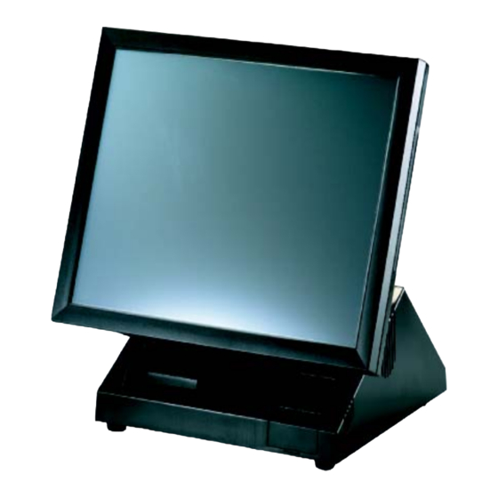
Identifying components This section describes the parts and connectors on the PT-6900. Front-right view Front-right view of PT-6900 Figure 1.2 15-inch TFT LCD touch screen Power button USB cover Green Power LED Amber Hard drive LED There are two USB connectors under the USB cover and two more USB connec- tors on the rear of the PT-6900. -
Page 14: Rear-Right View
Rear-right view Figure 1.3 Rear-right view of PT-6900 Customer display cover CompactFlash card cover Rear cover Rear cover latches Chapter 1 Getting Started ESCRIPTION... -
Page 15: Rear Connectors
Rear connectors Figure 1.4 shows the connectors on the rear of the PT-6900. You must remove the rear cover to access the connectors. See “Removing the rear cover” on page 7. Figure 1.4 Rear connectors labeled Line out Act LED (green) lights when network activity is detected... - Page 16 Plugging a phone line (RJ-11) into the LAN port (RJ-45 connector) may damage the connector. Connect only an RJ-45 plug to the LAN port. CAUTION Chapter 1 Getting Started...
-
Page 17: Removing The Rear Cover
Removing the rear cover Refer to the following to remove the rear cover. Rotate the display until it’s perpendicular. Open the rear cover latches. Remove the rear cover. Removing the rear cover... -
Page 18: Attaching The Customer Display
Attaching the customer display The PT-6900 may ship with a customer display attached. If you ordered the display separately, refer to the following to attach it. Remove the rear cover. See “Removing the rear cover” on page 7. Remove the screw. -
Page 19: Adjusting Display Angles
Use a desktop or counter that is stable and even. • Ensure there is enough room around the sides and rear of the PT-6900 for ventilation. • Ensure there is room to connect cables and that cables are long enough to reach peripheral devices or a power outlet. -
Page 20: Connecting Peripheral Devices
Connecting peripheral devices Peripheral devices such as a printer or scanner can be connected to the PT-6900. Refer to the user manual of the device you are connecting for instructions on installing drivers where needed. (Remove the rear cover to access the connec- tors. -
Page 21: Connecting A Cash Drawer
IMPORTANT Remove the rear cover. (See “Removing the rear cover” on page 7.) Connect the RJ-11 cable from the cash drawer to the RJ-11 connector on the PT-6900 as shown in Figure 1.8. Figure 1.8 Connecting a cash drawer Turn on the PT-6900. -
Page 22: Powering The Pt-6900 On And Off
Powering the PT-6900 on and off Refer to the following to power on and off the PT-6900. Remove the rear cover. See “Removing the rear cover” on page 7. Connect the power cable to the power con- nector on the PT-6900 rear panel and to the AC adapter. -
Page 23: Upgrading Components
This chapter describes how to upgrade components for the PT-6900. The following topics are described. • “Safety and precautions” • “Before you begin” on page 14 • “Installing a hard disk drive (HDD)” on page 14 • “Installing a CompactFlash card” on page 16 Safety and precautions Computer components and electronic circuit boards can be damaged by discharges of static electricity. -
Page 24: Chapter 2 Upgrading Components
To prevent scratching the case of the PT-6900, make sure the worktop surface is clean and flat. CAUTION Installing a hard disk drive (HDD) Refer to the following to install a HDD. - Page 25 Remove the two screws, then remove the hard disk drive tray. Connect the IDE and power cables to the HDD rear connectors. Place the hard disk drive on the tray, then secure it with a screw. Fold the cable as shown. Replace the HDD tray, then secure it with two screws.
-
Page 26: Installing A Compactflash Card
The CompactFlash card reader uses an IDE (Integrated Drive Electronics) interface and only supports storage cards. Plug and play is not supported so you must insert the card before you turn the PT-6900 POS on. After inserting a Com- pactFlash card, replace the cover to prevent the card from being accidently removed while power is on. -
Page 27: Bios Setup Utility
The BIOS (Basic Input and Output System) Setup Utility displays the system's configuration status and provides options to set system parameters. The parameters are stored in battery-backed-up CMOS RAM that saves this informa- tion even when the power is turned off. When the system is turned back on, the system is configured with the values found in CMOS.The following topics are described in this chapter. -
Page 28: Entering The Setup Utility
Entering the Setup Utility When you power on the system, BIOS enters the Power-On Self Test (POST) routines. POST is a series of built-in diagnostics performed by the BIOS. After the POST routines are completed, the following message appears: Press the delete key <Delete> to access the Award BIOS Setup Utility: Standard CMOS Features Advanced BIOS Features Advanced Chipset Features... -
Page 29: Using Bios
Date and Time The Date and Time items show the current date and time held by the PT-6900. If you are running a Windows OS, these items are automatically updated whenever you make changes to the Windows Date and Time Properties utility. -
Page 30: Ide Primary/Secondary Master/Slave
IDE Primary/Secondary Master/Slave This field is used to configure the IDE hard drive installed in the system. Move the cursor to highlight the IDE Pri- mary/Secondary Master/Slave fields and press <Enter>. The IDE Primary Master submenu opens: IDE HDD Auto-Detection IDE Primary Master Access Mode Capacity... -
Page 31: Advanced Bios Features
Access Mode This item defines special ways that can be used to access IDE hard disks such as LBA (Large Block Addressing). Leave this value at Auto and the system will automatically decide the fastest way to access the hard disk drive. Press <Esc>... -
Page 32: Cpu Feature
CPU Feature This menu comes with CPU-related parameters: Thermal Management Execute Disable Bit :Move Enter:Select F5: Previous Values Figure 3.5 CPU Feature submenu Thermal Management Shows the thermal management monitor. This item is non-configurable. The default setting is Thermal Monitor 1. Execute Disable Bit The default setting is Enabled. -
Page 33: Advanced Chipset Features
Advanced Chipset Features This option displays critical timing parameters of the mainboard. Leave the items on this menu at their default settings unless you are very familiar with the technical specifications of the system hardware. If you change the values incor- rectly, you may introduce fatal errors or recurring instability into the system. - Page 34 Boot Display If you connect an external display to the PT-6900, you can use this setting to turn off the LCD and only use the external display. To use dual displays this must be set to CRT+LCD. The default setting is CRT+LFP.
-
Page 35: Integrated Peripherals
Integrated Peripherals This option defines the operation of peripheral components on the system's input/output ports. OnChip IDE Device Onboard Device SuperIO Device Watch Dog Timer Select Com3 With Voltage Com4 With Voltage :Move Enter:Select F5: Previous Values Figure 3.7 Integrated Peripherals menu OnChip IDE Device (See “OnChip IDE Device”... -
Page 36: Onchip Ide Device
OnChip IDE Device Use this item to enable or disable the PCI IDE channels that are integrated on the mainboard. Select the item and press <Enter> to open the following menu: OnChip Primary PCI IDE IDE Primary Master PIO IDE Primary Slave IDE Primary Master UDMA IDE Primary Slave OnChip Secondary PCI IDE... -
Page 37: Onboard Device
Onboard Device Use this item to enable or disable the PCI devices that are integrated on the mainboard. Select the item and press <Enter> to open the following menu: USB Controller USB 2.0 Controller USB Keyboard Support AC97 Audio AC97 Modem Init Display First :Move Enter:Select... -
Page 38: Superio Device
SuperIO Device Use this item to change settings for I/O devices. Select the item and press <Enter> to open the following menu: Onboard Serial Port 1 Onboard Serial Port 2 UART Mode Select Onboard Parallel Port Parallel Port Mode x EPP Mode Select x ECP Mode Use DMA Onboard Serial Port 3 Serial Port 3 Use IRQ... - Page 39 Serial Port 3 Use IRQ This option is used to assign the IRQ for the onboard serial port 3. The default setting is IRQ3. Onboard Serial Port 4 This option is used to assign the I/O address for the onboard serial port 4. The default setting is 2E8. Serial Port 4 Use IRQ This option is used to assign the IRQ for the onboard serial port 4.
-
Page 40: Power Management Setup
NOTE PT-6900. ACPI Suspend Type Use this item to define how the system suspends. In the default, S1(POS), the suspend mode is equivalent to a software power down. - Page 41 Video Off In Suspend This option defines if the video is powered down when the system is put into suspend mode. The default setting is Yes. Suspend Type This option defines the suspend type for the video. The default setting is Stop Grant. MODEM Use IRQ This option sets the IRQ for the modem chip.
-
Page 42: Pnp/Pci Configurations
PnP/PCI Configurations This option configures how PnP (Plug and Play) and PCI expansion cards operate in the system. Both the ISA and PCI buses on the mainboard use system IRQs (Interrupt ReQuests) and DMAs (Direct Memory Access). You must set up the IRQ and DMA assignments correctly through the PnP/PCI Configurations menu;... -
Page 43: Irq Resources
IRQ Resources This menu can only be accessed when the Resources Controlled by menu is set to Manual. In the IRQ Resources sub-menu, if you change any of the IRQ assignations to Legacy ISA, then that Interrupt Request Line is reserved for a legacy ISA expansion card. Press <Esc> to close the IRQ Resources sub-menu. IRQ-3 assigned to IRQ-4... -
Page 44: Pc Health Status
PC Health Status On mainboards that support hardware monitoring, this item lets you monitor the parameters for critical voltages, and critical temperatures. Several fields are for information only and are not configurable. CPU Warning Temperature Current System Temp. Current CPU Temperature Current CPUFAN1 Speed Current CPUFAN2 Speed + 5 V... -
Page 45: Frequency/Voltage Control
Frequency/Voltage Control This item enables you to set the clock speed and system bus for the system. The clock speed and system bus are deter- mined by the kind of processor you have installed in the system. Auto Detect PCI Clk Spread Spectrum :Move Enter:Select... -
Page 46: Other Bios Options
Other BIOS Options This section covers the other options that are available from the main menu: Standard CMOS Features Advanced BIOS Features Advanced Chipset Features Integrated Peripherals Power Management Setup PnP/PCI Configurations PC Health Status ESC: Quit F10: Save & Exit Setup Load Fail-Safe Defaults This option opens a dialog box that lets you load fail-safe defaults for all appropriate items in the Setup Utility. -
Page 47: Set Supervisor And User Passwords
4. Press <Enter> to load the defaults. Set Supervisor and User Passwords These items can be used to install a password. A Supervisor password takes precedence over a User password, and the Supervisor can limit the activities of a User. To install a password, follow these steps: 1. -
Page 48: Appendix
If failure is detected in an area other than the mainboard (such as the keyboard or an adapter card), an error message is displayed on the screen and testing is stopped. If your system does not successfully complete the POST, but displays a blank screen, have the PT-6900 serviced. Beep Errors at POST There are two kinds of beep codes in the BIOS. -
Page 49: Beep Message Errors At Post
The memory card is not correctly installed or is damaged. OLUTION Replace the battery. Replace the battery. Have the PT-6900 serviced. Have the PT-6900 serviced. Have the PT-6900 serviced. Have the PT-6900 serviced. Have the PT-6900 serviced. Have the PT-6900 serviced. -
Page 50: General Problems
If the same problem occurs, replace the mouse or keyboard. Check that the AC adapter is connected to the PT-6900 and the power cord is plugged into a working electrical outlet. Check that the power is on. (Press the power switch again for confirmation.) -
Page 51: Having The Pt-6900 Serviced
If you are unable to solve the problem, you should have the projector serviced. Pack the projector in the original car- ton. (See “Unpacking the PT-6900” on page 1.) Include a description of the problem and a checklist of the steps you took when trying to fix the problem. -
Page 52: Specifications
Specifications Processor Memory Resolution Brightness Viewing Angle Touch Screen Network Storage Expansion Power Supply I/O Ports Operating System Peripherals Temperature Humidity Dimensions Weight Certifications Specifications subject to change without notice Specifications ESCRIPTION Intel Celeron-M 1GHz CPU 256MB DDR up to 2GB, 2 memory slots 15"...
Need help?
Do you have a question about the PT-6900 and is the answer not in the manual?
Questions and answers